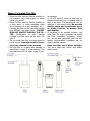
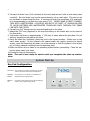
1
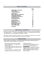
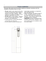
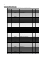
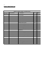
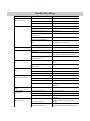
Proud member of Canadian Institute of Plumbing & Heating. Proud member of Canadian Water Quality Association. 1. Read all instructions carefully before operation. 2. Avoid pinched o-rings during installation by applying (provided with install kit) NSF certified lubricant to all seals. 3. This system is not intended for treating water that is microbiologically unsafe or of unknown quality without adequate disinfection before or after the system. REVISION # 1 REVISION DATE November 10, 2012 Canadian Head Office 655 Park St. Regina, SK S4N 5N1 Eastern Sales & Distribution 20 Steckle Place, Unit 21 Kitchener ON N2E 2C3 Owners Manual 485IS Greensand Filter 2 Table of Contents Unpacking / Inspection Safety Guide Proper Installation Specification Before Starting Installation Sizing Requirements Installation Instructions System Start Up Plumbing Clean Up Programming About The System Maintenance Sanitizing Procedure Main Repair Parts Trouble Shooting Warranty PAGE 2 2 3 4 5 7 8 9 11 12 13 15 15 16 23 24 Unpacking / Inspection Be sure to check the entire unit for any shipping damage or parts loss. Also note damage to the shipping cartons. Contact the transportation company for all damage and loss claims. The manufacturer is not responsible for damages in transit. Small parts, needed to install the softener, are in a parts bag. To avoid loss of the small parts, keep them in the parts bag until you are ready to use them. Safety Guide For your safety, the information in this manual must be followed to minimize the risk of electric shock, property damage or personal injury. Check and comply with your provincial / included transformer. state and local codes. You must follow Transformer must be plugged into an inthese guidelines. door 120 volt, grounded outlet only. Use care when handling the filter tank. Do WARNING: This system is not innot turn upside down, drop, drag or set on tended for treating water that is microbiosharp protrusions. logically unsafe or of unknown quality The system works on 12 volt-60 Hz electriwithout adequate disinfection before or cal power only. Be sure to use only the after the system. 3 Proper Installation This water filter system must be properly installed and located in accordance with the Installation Instructions before it is used. Do not install or store where it will not be sweat-solder connections, as required by exposed to temperatures below freezing or state and federal codes. exposed to any type of weather. Water Maximum allowable inlet water pressure is freezing in the system will break it. Do not 125 psi. If daytime pressure is over 80 attempt to treat water over 100°F. psi, night time pressure may exceed the Do not install in direct sunlight. Excessive maximum. Use a pressure reducing valve sun or heat may cause distortion or other to reduce the flow if necessary. damage to non-metallic parts. WARNING: Discard all unused parts and Properly ground to conform with all govpackaging material after installation. Small erning codes and ordinances. parts remaining after the installation could Use only lead-free solder and flux for all be a choke hazard. 4 Specifications Specifications Service Flow Rates Normal Peak Backwash Flow Rate Compensated Iron Removal Capacity KMn04 per Regen Filter Media Volume - Cubic Feet Filter Tank Size Tank Jacket / Media Loaded Shipping Weight Maximum Combination of Iron X 1, Manganese X 2, H2S X3 Maximum Iron (Ferrous) Maximum Manganese Maximum Hydrogen Sulfide Bacterial Iron Minimum pH Plumbing Connections Electrical Requirements Water Temperature Water Pressure 485IS-75 15054016 485IS-100 15054017 485IS-150 15054018 485IS-200 15054019 485IS-300 15054020 3.0 gpm 4.0 gpm 3.5 gpm 4,500 ppm 4 oz 3.0 gpm 5.0 gpm 4.0 gpm 6,000 ppm 4 oz 4.0 gpm 8.0 gpm 5.0 gpm 9,500 ppm 4 oz 5.0 gpm 10.0 gpm 7.0 gpm 12,000 ppm 8 oz 6.0 gpm 12.0 gpm 10.0 gpm 18,000 ppm 8 oz 0.75 ft3 8x44 Yes 113 lbs 1.0 ft3 9x48 Yes 129 lbs 1.5 ft3 10x54 Yes 179 lbs 2.0 ft3 12x52 No 233 lbs 3.0 ft3 14x65 No 352 lbs 10.0 ppm 7.0 ppm 5.0 ppm 3.0 ppm 0.0 ppm 7.0 3/4" (Optional 1") Input 120V 60 Hz - Output 12V 650mA Min 39 - Max. 100 degrees Fahrenheit Min. 20 - Max. 125 psi Continuous operation at flow rates greater than the service flow rate may affect capacity and efficiency per formance. The manufacturer reserves the right to make product improvements which may deviate from the specifications and descriptions stated herein, without obligation to The system consists of three major components: a back washable filter containing oxygen charged manganese greensand, a chemical feeder with shutoff float which delivers an accurately measured volume of potassium permanganate solution for each regeneration, and a meter initiated control valve which governs the operation of the system. As water passes through the filter bed, it comes in contact with the oxygen charged media. This causes iron, manganese and sulfur to oxidize. The undesirable compounds are then trapped in the filter bed. Eventually change previously manufactured products or to note the change. Peak flow rates are intended for intermittent use only and are for residential application only At the stated service flow rates, the pressure drop through these devices will not exceed 15 psig the oxygen in the filter becomes depleted and regeneration is necessary. Regeneration takes place during the night while you sleep. First, backwashing cleans the filter bed, and then concentrated potassium permanganate solution is passed through it, recharging the bed with oxygen. A rapid rinse removes any remaining potassium and a volume of water is returned to the feeder to dissolve enough potassium permanganate for the next regeneration. All functions are performed automatically. 5 Before Starting Installation Tools, Pipe, and Fittings, Other Materials Pliers Screwdriver Teflon tape Razor knife Two adjustable wrenches Additional tools may be required if modification to home plumbing is required. Plastic inlet and outlet fittings are included with the softener. To maintain full valve flow, 3/4” or 1” pipes to and from the softener fittings are recommended. You should maintain the same, or larger, pipe size as the water supply pipe, up to the softener inlet and outlet. Use copper, brass, or PEX pipe and fittings. Some codes may also allow PVC plastic pipe. ALWAYS install the included bypass valve, or 3 shut-off valves. Bypass valves let you turn off water to the softener for repairs if needed, but still have water in the house pipes. 5/8” OD drain line is needed for the valve drain. A 10’ length of hose is included. with some models. A length of 5/8” OD drain line tubing is needed for the brine tank over flow fitting (optional). Nugget or pellet water softener salt is needed to fill the cabinet or brine tank. 6 Where To Install The Filter Place the filter tank as close as possible to ter damage. the pressure tank (well system) or water A 120 volt electric outlet, to plug the inmeter (city water). cluded transformer into, is needed within 6 Place the filter tank as close as possible to feet of the filter. The transformer has an a floor drain, or other acceptable drain attached 6 foot power cable. Be sure the point (laundry tub, sump, standpipe, etc.). electric outlet and transformer are in Connect the filter to the main water supply an inside location, to protect from pipe BEFORE the water heater. DO NOT wet weather. RUN HOT WATER THROUGH THE FIL- If installing in an outside location, you TER. Temperature of water passing must take the steps necessary to assure through the filter must be less than 100 the filter, installation plumbing, wiring, deg. F. etc., are as well protected from the eleDo not install the filter in a place where it ments, contamination, vandalism, etc., as could freeze. Damage caused by freezwhen installed indoors. ing is not covered by the warranty. Keep the filter out of direct sunlight. Put the filter in a place water damage is The sun’s heat may soften and distort least likely to occur if a leak develops. The plastic parts. manufacturer will not repair or pay for wa- 7 Sizing Requirements Water Pressure The water system must have a pump big enough to deliver the recommended backwash rate with a minimum pressure at the inlet of the filter of 30 psi. If the existing system cannot do this, it must be upgraded to do so. Whenever possible, the water system should be adjusted to deliver at least 30 psi for even more satisfactory results. Backwash Flow Rates The most important criteria in sizing a filter is the capacity of the pump. The water must pass through the filter media at the proper service flow rate. The filter must also be backwashed at a flow rate sufficient to dislodge and remove the captured particles. Failure to provide sufficient water will cause a build-up of particles in the filter media, impairing its ability. In order for your filter to backwash and rinse properly, your pump must be capable of providing the backwash flow rates indicated on page 4. Check Your Pumping Rate Two water system conditions must be checked carefully to avoid unsatisfactory operation or equipment damage: 1. 2. Minimum water pressure required at the filter tank inlet is 20 psi. Measuring the pumping rate of your pump: With the pressure tank full, draw water into a container of known volume, and measure the number of gallons drawn until the pump starts again. This is draw-down. Divide this figure by cycle time and multiply the result by 60 to arrive at the pumping rate in gallons per minute (gpm). To aid in your calculation, insert the date in the following formula: DRAW-DOWN ______ ÷ CYCLE TIME _______ x 60 = PUMPING RATE ________ (gals) (secs.) (Gpm) EXAMPLE: CYCLE TIME is 53 seconds. DRAW-DOWN is 6 gallons; then, PUMPING RATE equals: 6 gallons ÷ 53 seconds x 60 = 6.8 gpm See chart on page 4 for minimum flow rates. NOTE: If your pumping rate is inadequate for the model, do not install your filter until the problem has been corrected. 8 Capacity An iron filter with one cubic foot of filter media regenerated with one Potassium Permanganate feeder will work well for most residential applications. For example, with iron in the range of 3-6 ppm, most filters will need to regenerate every two or three days providing an average family size of four or five people. The specification chart on page 4 shows the iron removal capacity in ppm that can be expected on automatic iron filters. The specifications are based on obtaining 6,000 ppm of capacity for each cubic foot of filter media. Two different Potassium Permanganate feeders are available – one feeding 2 oz. per regeneration, the other feeding 4 oz. In order to obtain the above capacities, the pH of the water being treated must be 7.0 or above. In the event the water is below 7.0, it must be treated with the appropriate equipment before going through the filter. Removal Of Iron, Manganese & Hydrogen Sulfide ***IMPORTANT*** For the purpose of sizing a filter, consider 1 ppm of manganese equal to 2 ppm of iron and 1 ppm of hydrogen sulphide equal to 3 ppm of iron. Manganese and hydrogen sulphide (sulphur) are more difficult to oxidize than iron. Therefore, we suggest that, when making your sizing calculations and regeneration frequency calculations, calculate iron x 1, manganese x 2 and hydrogen sulphide x 3. All three must equal less than 10 ppm. Manganese is often present in water when iron is present. Hydrogen sulphide can normally be identified by a strong rotten egg odour. Installation Instructions 1. If your hot water tank is electric, turn off the power to it to avoid damage to the element in the tank. 2. If you have a private well, turn the power off to the pump and then shut off the main water shut off valve. If you have municipal water, simply shut off the main valve. Go to the faucet, (preferably on the lowest floor of the house) turn on the cold water until all pressure is relieved and the flow of water stops. 3. Locate the filter tank close to a drain where the system will be installed. The surface should be clean and level. 4. Connect the inlet and outlet of the filter using appropriate fittings. Perform all plumbing according to local plumbing codes. Use a ½” minimum pipe or tubing size for the drain line ON COPPER PLUMBING SYSTEMS BE SURE TO INSTALL A GROUNDING WIRE BETWEEN THE INLET AND OUTLET PIPING TO MAINTAIN GROUNDING. Any solder joints near the valve must be done before connecting any piping to the valve. Always leave at least 6" (152 mm) between the valve and joints when soldering pipes that are connected to the valve. Failure to do this could cause damage to the valve. 9 5. Connect the drain hose (10 ft included) to the valve and secure it with a hose clamp (also included). Run the drain hose to the nearest laundry tub or drain pipe. This can be ran up overhead or down along the floor. If running the drain line more than 20 ft overhead, it is recommended to increase the hose size to 3/4”. NEVER MAKE A DIRECT CONNECTION INTO A WASTE DRAIN. A PHYSICAL AIR GAP OF AT LEAST 1.5” SHOULD BE USED TO AVOID BACTERIA AND WASTEWATER TRAVELLING BACK THROUGH THE DRAIN LINE INTO THE FILTER. 6. Connect the 3/8” tubing from the chemical feed tank to the valve. 7. Attach the 5/8” hose (supplied) to the over flow fitting on the feeder and run the hose to the floor drain. 8. Add water until there is approximately 1” (25 mm) of water above the grid plate. Do not add any chemical to the tank at this time. 9. Using the Allen Key (included), place the unit in the bypass position. Slowly turn on the main water supply. At the nearest cold treated water tap nearby remove the faucet screen, open the faucet and let water run a few minutes or until the system is free of any air or foreign material resulting from the plumbing work. 10.Make sure there are no leaks in the plumbing system before proceeding. Close the water tap when water runs clean. 11.Proceed to start up instructions. Note: The unit is not ready for service until you complete the start-up instructions. System Start-Up Key Pad Configuration SETTINGS This function is to enter the basic set up information required at the time of installation. MANUAL REGEN This function is to initiate an immediate or delayed manual regeneration. DOWN / UP Increase or decrease the value of the settings while in the programming mode. 10 Manual Regeneration (Step / Cycle Valve) DELAYED REGENERATION Press and release the MANUAL REGEN. Button to set a delayed regeneration that will occur at the regeneration time. The main display page will show DELAYED REGEN ON. To cancel press and release the MANUAL REGEN. Button. The main display page will show DELAYED REGEN OFF. IMMEDIATE REGENERATION To start an immediate regeneration (or step valve through each position), press and hold the MANUAL REGEN. Button for 3 seconds (until beeps). The valve will start an immediate regeneration. Press any key to skip to the next cycle. Start-up Instructions 1. Plug the power transformer into an approved power source. Connect the power cord to the valve. 2. When power is supplied to the control, the screen will display “INITIALIZING WAIT PLEASE” while it finds the service position. 3. Start an Immediate Manual Regeneration. The valve will immediately start moving to the BACKWASH position. 4. Once in the BACKWASH cycle, open the inlet on the bypass valve slowly and allow water to enter the unit. Allow all air to escape from the unit before turning the water on fully then allow water to run to drain for 3-4 minutes or until all media fines are washed out of the softener indicated by clear water in the drain hose. 5. Press any button to advance to the CHEMDRAW position. Check the water level in the chemical feed tank to insure the valve is drawing water properly. 6. Press any button and advance to the RINSE position. Check the drain line flow. Allow the water to run for 3-4 minutes or until the water is clear. 7. Press any button to advance to the REFILL position. Check that the valve is filling water into the chemical tank. Allow the valve to refill until the float shuts off the water flow to the tank. 8. The valve will automatically advance to the SERVICE position. Open the outlet valve on the bypass, then open the nearest treated water faucet and allow the water to run until clear, close the tap and replace the faucet screen. 9. Cautiously pour Potassium Permanganate t into the chemical tank. Replace the cover and the safety screws. 10.Manually initiate a regeneration after about one hour (time for the chemical to dissolve) to activate the manganese greensand. 11. Program unit. 11 Plumbing System Clean-Up The following procedures are guidelines only but have proven successful in most instances. Under no circumstances should any procedure outlined below be followed if contrary to the appliance manufacturer's instructions. Should there be any questions concerning the advisability of performing a procedure, it is strongly recommended the manufacturer's authorized service outlet be consulted prior to performing the procedure. short time, to iron-fouled water need to be cleaned of the precipitated iron that has collected in them or iron bleed (staining) will continue to be a problem. Depending on the amount of iron in the water and the length of time the water system has been exposed to iron fouling, select from the following procedures those that apply to the type of system and appliances that need to be cleaned to assure iron-free water at all The plumbing system and water using appli- points of use. ances that have been exposed, even for a Softener It isn't uncommon that the softener was inwarm mineral cleaner solution to be drawn stalled in an effort to remove ferrous (clear into the mineral bed. water) iron from the water supply. Typically a 3. Then immediately close the main water softener will remove some ferrous iron until supply valve or turn the power off to the the resin bed becomes fouled to the extent pump and proceed with the filter installathat it will lose both hardness removal capaction. During the time required to install the ity and the limited capacity for iron removal. filter system, the iron-fouled softener resin This is the condition to expect the softener to will be chemically cleaned. be in when planning a system clean-up. Prior 4. After the filter installation is completed and to closing the main supply valve or turning final adjustments have been made, with power off to a private well system and prethe water turned on and the brine draw paratory to installing the filter system, do the tube reconnected, reposition the timer on following: the softener to the backwash position. Allow the timer to perform an automatic re1. Disconnect the brine draw line from the generation cycle. During backwash of the brine cabinet and place the loose end into softener, all iron cleaned from the resin a five gallon plastic pail filled with a soluwill be washed down the drain. It is advistion of warm water and 4 oz. of resin minable, after chemically cleaning the soferal cleaner. tener, to regenerate the system twice to 2. Advance the control timer to the brine fully restore capacity lost due to irondraw position (refer to instructions profouling. vided with your softener). Allow all the 12 Water Heater If the water heater has been exposed to both flushing until the water runs clear to the iron and hardness for a long period of time, drain. replacement of the heater tank may be the 3. If, after approximately 30 minutes of flushonly practical solution to prevent continued ing, water does not clear, terminate the staining originating from this source. After flushing operation. Refill hot water heater completing the installation of the chemical with water and pour approximately 1/2 free iron filter, clean the water heater by folgallon of household bleach into the top of lowing these instructions: the heater tank. Allow bleach solution to stand in tank for 20 to 30 minutes. Flush 1. Shut off the energy supply to the water the tank again until water is clear at the heater and close the heater inlet water drain. Turn energy supply on. valve. NOTE: If water does not clear in approxi2. Drain hot water tank completely. Open mately 10 minutes, water heater should inlet water valve, allowing heater tank to probably be replaced. be refilled with iron-free water. Continue Programming Instructions Settings Press SETINGS key (3 SECONDS / BEEP) VALVE MODE GREENSAND TIME OF DAY 12:01 PM YEAR 2012 MONTH AUGUST DAY 21 REGEN DAYS 3 DAYS GALLONS OFF REGEN TIME 12:00 AM PROGRAMMING COMPLETE TIME OF DAY, YEAR, MONTH, DAY, Time of day is for normal operation of system and the scheduling of the regeneration time. The date is used in a diagnostic function to track the last time the system regenerated. REGEN DAYS This value is the number of days between regenerations or back washes to clean the filters. GALLONS Default value is OFF. Adjust the GALLONS to set the capacity. This will cause the unit to regenerate either when the gallons remaining goes to zero or the days between regeneration is zero. Which ever occurs first. REGEN TIME This setting determines the time of day to perform a scheduled regeneration. The normal regen time for a filter is 12:00 AM. 13 About The System Control Operation During A Power Failure In the event of a power failure, the valve will keep track of the time and day for 48 hours. The programmed settings are stored in a non-volatile memory and will not be lost during a power failure. If power fails while the unit is in regeneration, the valve will finish regeneration from the point it is at once power is restored. If the valve misses a scheduled regeneration due to a power failure, it will queue a regeneration at the next regeneration time once power is restored. Main Display The main display page will pause on the Date and Time page for 5 seconds. Then it will continually scroll through all of the system diagnostic display pages. Depending on the Valve Type some pages will not be displayed. To manually scroll through the diagnostics, press the down or up key. To reset the TOTAL REGENS, TOTAL GALLONS OVER RUN TOTAL, or PEAK flow rates, press and hold the MENU until the value changes to zero. PARAMETER JULY/17/2012 8:30 PM TOTAL 1,500 GAL REMAIN 1,200 GAL PEOPLE 2 RESERVE 150 GAL EST. DAYS TO NEXT REGEN 06 DAYS LAST REGEN 9/24/12 TOTAL REGENS 10 TOTAL GALLONS 001590 GAL OVER RUN TOTAL 0500 GAL CURRENT 1.5 GPM PEAK 6.5 GPM DELAYED REGEN OFF REGEN TIME 2:00 AM REFILL TIME 3:00 MIN VALVE MODE SOFTENER UF DESCRIPTION Month, Day, Year, Time The total amount is the system capacity when fully regenerated. The remaining is the capacity left in the system. Number of people in the household and the calculated reserve capacity. When remaining reaches reserve capacity a regeneration will be scheduled. The estimated number of days until the next regeneration will occur. The date of the last regeneration. The total number of regenerations. The total amount of gallons treated by the system. The total amount of water that has exceeded the system capacity over the last 4 regenerations. When remaining goes to zero, the gallons used will be added to over run total. The current flow rate and the peak flow rate since the last regeneration. Advises whether a delayed regeneration has been scheduled manually or automatically. The current setting for regeneration time. The current calculated refill time. The current setting of the valve mode. New Sounds You may notice new sounds as your water softener operates. The regeneration cycle lasts up to 180 minutes. During this time, you may hear water running intermittently to the drain. 14 Regeneration Process When the system capacity is near exhausted, a regeneration is necessary to restore the system to full capacity. The table below explains the regeneration steps. Step Name #1 Back Wash #2 Chem-Draw #3 Rinse #4 Refill Description Fresh water is introduced to the bottom of the tank flowing upwards expanding the ion exchange resin to rinse out any dirt or small particles to the drain and to un-compact the bed to restore full service flow rates. The chemical solution is introduced slowly to the top of the tank flowing down through the filter bed restoring system capacity. Fresh water is introduced from the top of the tank down flowing down through the ion exchange resin rinsing any excess brine solution out to the drain. Filtered water is added to the chemical tank until the safety float in the tank shuts off the flow of water. The water will mix with the chemicals to become saturated for the next regeneration. Automatic Raw Water Bypass During Regeneration The regeneration cycle can last 30 to 180 minutes, after which soft water service will be restored. During regeneration, raw water is automatically bypassed for use in the household. Hot water should be used as little as possible during this time to prevent raw water from filling the water heater. This is why automatic regeneration is set for sometime during the night and manual regenerations should be performed when little or no water will be used in the household. Normal regeneration time is 12:00 AM. System Configuration Suggested Iron Filter Valve Configuration Brine Line Flow Drain Line Flow Tank Size (Diameter) Injector Control (BLFC) Control (DLFC) #5 (3.5 GPM) 8" 9" #A (5.0 GPM) #2 GREY (PVC) (0.70 GPM) 10" #A (5.0 GPM) 12" #B (7.0 GPM) 14" #C (10.0 GPM) 15 Manual Bypass In the case of emergency, such as an overflowing brine tank, you can isolate your water softener from the water supply using the bypass valve located at the back of the control. In normal operation the bypass is open with the on/off knobs in line with the inlet and outlet pipes. To isolate the softener, simply rotate the knobs clockwise (as indicated by the word BYPASS and arrow) until they lock. You can use your water related fixtures and appliances as the water supply is bypassing the softener. However, the water you use will be hard. To resume soft water service, open bypass valve by rotating the knobs counterclockwise. Maintenance Adding Salt Use only crystal water softener salt. Check the salt level monthly. It is important to maintain the salt level above the water level. To add salt, simply lift the salt lid and add the salt directly into the brine tank. Be sure the brine well cover is on and fill only to the height of the brine well. Bridging Humidity or wrong type of salt may create a cavity between the water and the salt. This action, known as “bridging”, prevents the brine solution from being made, leading to your water supply being hard. If you suspect salt bridging, carefully pound on the outside of the brine tank or pour some warm water over the salt to break up the bridge. This should always be followed up by allowing the unit to use up any remaining salt and then thoroughly cleaning out the brine tank. Allow two hours to produce a brine solution, then manually regenerate the softener. 16 Cleaning or Replacing Injectors Sediment, salt and silt will restrict or clog the injector. A clean water supply and pure salt will prevent this from happening. The injector assembly is located on the right side of the control valve. This assembly is easy to clean. TIP: There are marks on the injector holder that must be lined up to the marks on the valve to fully insert the holder into the hole in the valve body TIP: Place the o-rings A25 and A26 onto the valve before installing A33. 1. Shut off the water supply to your filter and reduce the pressure by opening a cold soft water faucet. 2. Using a screwdriver, remove the four screws holding the injector cover to the control valve body. 3. Carefully remove the assembly and disassemble as shown in above figure. 4. The injector orifice is removed from the valve body by carefully turning it out with a large screwdriver. Remove the injector throat the same way. 5. Carefully flush all parts including the screen. Use a mild acid such as vinegar or Pro-Rust Out to clean the small holes in the orifice and throat. 6. Reassemble using the reverse procedure. 17 Replacing Brine Line Flow Control (BLFC) TIP: Markings on the BLFC washer should face the direction as shown here. 1. Remove the red clip that secures the brine elbow. 2. Remove the BLFC holder from the elbow fitting. 3. Split the BLFC holder apart and remove the flow washer. 4. Reassemble using the reverse procedure. Replacing Drain Line Flow Control (DLFC) 1. Remove the red clip that secures the drain line elbow. 2. Remove the BLFC washer from the elbow fitting. 3. Reassemble using the reverse procedure. 18 Main Repair Parts Main Repair Parts - Connectors A A A C B F D E A REPLACEMENT PARTS - CONNECTORS Replacement Part Number Part Description DWG # Quantity 60010020 3/4" NPT ELBOW A 2 60010019 1" NPT STRAIGHT A 2 60010023 3/4" NPT STRAIGHT A 2 60010079 VALVE COUPLING INLET B 1 60010101 VALVE COUPLING OUTLET (METER SIDE) C 1 60010025 PLASTIC SECURE CLIP D 2 60010046 BYPASS SS CLIP E 2 60010047 BYPASS SS SCREW F 2 19 Control Valve Exploded View VALVE REPAIR PARTS LIST Replacement Part Description Part Number Replacement Part Number Part Description 60010127 60010126 60010035 60010034 60010033 60010032 60010031 60010128 60010110 60010082 60010129 60010171 60010130 60010131 60010132 60010133 60010135 60010136 60010137 60010138 85HE UPFLOW PISTON ASSEMBLY 85HE DOWNFLOW PISTON ASSEMBLY 85HE SEAL & SPACER KIT 85HE DLFC #1 1.5 GPM 85HE DLFC #2 2.0 GPM 85HE DLFC #3 2.4 GPM 85HE DLFC #5 3.5 GPM 85HE DLFC #A 5.0 GPM 85HE DLFC #B 7.0 GPM 85HE DLFC #C 10.0 GPM INJECTOR SET #0000 BLACK INJECTTOR SET #000 GREY INJECTOR SET #00 VIOLET INJECTOR SET #0 RED INJECTOR SET #1 WHITE INJECTOR SET #2 BLUE INJECTOR SET #3 YELLOW BLFC 0.2 GPM BLFC 0.3 GPM BLFC 0.7 GPM 20 Control Valve Parts List 485HE CONTROL VALVE (DOWNFLOW) Replacement Part Number MFG Part Number Part Description DWG # Quantity 5056087 Screw-M5x12(Hexagon) A01 3 5056088 Screw-M5x16(Hexagon With Washer) A02 2 5056047 End Plug Retainer A03 1 5031016 BNT85HE Piston Rod A04 1 5056097 Piston Pin A05 1 5031015 BNT85HE Quad Ring Plug Cover A06 1 5056070 Quad Ring A07 2 5031011 BNT85HE End Plug A08 1 5031014 BNT85HE Piston Retainer A09 1 5057001 BNT85HE Piston(Electrical Downflow) A10 1 5056073 Seal A11 5 5056021 Spacer A12 4 5010082 Drain Fitting-B A13 1 5031005 BNT85HE Spacer A14 1 5056186 DLFC-2# A15 1 5056172 Secure Clip-s A16 2 5031002 BNT85HE Valve Body A17 1 5056508 Screw-M5x12(Hexagon With Washer) A18 5 5030004 BNT85 End Cover A19 1 5030013 O-Ring-¢ 30×2.65 A20 1 5056063 O-Ring-¢78.74×5.33 A21 1 26010103 O-Ring-¢25×3.55 A22 1 7060007 13000426 Valve Bottom Connector A23 1 Screw-ST2.9X13(Large Washer) A24 2 5031022 O-Ring-¢32×3 A25 1 5031021 O-Ring-¢18×3 A26 1 5031013 Injector Plug Body A27 1 30110007 Plastic Ball ¢6 A28 1 30040089 Injector Throat A29 2 BNT85HE Injector Fixed Sleeve A30 1 30040090 Injector Nozzle A31 2 5056103 Injector Screen A32 1 5031003 BNT85HE Injector Cover Body A33 1 5031018 O-Ring-¢40×2.65 A34 1 5031004 BNT85HE Injector Cover Cap A35 1 5031027 Screw-M5x25(Hexagon With Washer) A36 4 5056075 Seal Mat A37 1 5056134 O-Ring-¢12×2 A38 3 5056054 Injector Stem A39 1 5056031 Injector Spacer A40 1 5056081 O-Ring-¢12.5×1.8 A41 1 5056030 Injector Cap A42 1 5056093 Injector Screen A43 1 5010049 Special Washer A44 1 5056105 Retaining Ring A45 1 5031010 BNT85HE BLFC Fixed Sleeve A46 2 5056076 BLFC-2# A47 1 5005629 Injector Fitting(3/8".Elbow) A48 1 5031012 21 Power Head Exploded View 22 Power Head Parts List 485HE POWER HEAD (DOWNFLOW) Replacement Part Number MFG Part Number Part Description DWG # Quantity 5056084 Screw-ST3.5X13 B01 10 5010037 Screw-ST2.9X10 B02 9 13000416 Screw-ST3.5X25 B03 1 5031007 BNT85HE Piston Rod Guide Plate B04 1 5056510 Motor-12v/2rpm B05 1 5030014 Motor Power Cable 11700005 Wire Connector 5056098 Motor Pin B06 1 5031006 BNT85HE Mounting Plate B07 1 1 2 5030009 BNT85 Drive Gear B08 1 13000426 Screw-ST2.9X13(Large Washer) A24 2 5056139 Washer-3x13 B09 1 5030007 BNT85 Main Gear B10 1 5030005 BNT185 Housing B11 1 5031017 BNT85HE Brine Gear(Downflow) B12 1 5010023 Magnet(3×2.7) B13 1 5056141 Washer-4x12 B14 1 5056166 Screw-ST4.2X12(Large Washer) B15 1 5031016 BNT85HE Piston Rod A04 1 5010036 Screw-ST3.5X16 B16 1 5031026 BNT85HE Main Pcb(Downflow) B17 1 5010031 Meter Assembly 1 5010046 Meter Strain Rlief 1 5010029 Power Cable 1 5010035 Power Strain Rlief 1 19010105 Wire Rope-3×100 2 5031024 BNT85HE Display(Downflow) 5030021 BNT85 Wiring Harness 5030003 BNT85 Cover B18 1 1 B19 1 23 Trouble Shooting Issue A. Unit fails to initiate a regeneration cycle. B. Water is red. Possible Cause 1. No power supply. Possible Solution Check electrical service, fuse, etc. 2. Defective circuit board. Replace faulty parts. 3. Power failure. Reset time of day. 1. By-pass valve open. Close by-pass valve. 2. Out of KMnO4. Add to tank. 3. Plugged injector / screen. Clean parts. 4. Flow of water blocked to chemical tank. Check for flow to tank. 5. Rusty water in how water tank. Sediment in tank disturbed. 6. Leak between valve and central tube. Repeat flushing of hot water tank required. 7. Internal valve leak. Replace valve seals, spacer, and piston assembly. Replace chemical tank. Check if central tube is cracked or o-ring is damaged. Replace faulty parts. C. Chemical use is high. 1. Defective chemical tank system. D. Low water pressure. 1. Iron or scale build up in line Clean pipes. feeding unit. 2. Iron build up inside valve or tank. Clean control and add resin cleaner to clean bed. Increase regeneration frequency. E. Filter media in drain line. 3. Inlet of control plugged due to foreign material. Remove piston and clean control valve. 1. Air in water system. Check well system for proper air eliminator control. Check for proper flow rate. 2. Incorrect drain line flow control (DLFC) button. F. Too much water in brine 1. Plugged injector or screen. tank. 2. Valve not regenerating. 3. Foreign material in brine valve. G. Unit fails to draw regenerate chemicals. Clean parts. Replace circuit board, motor, or control. Clean parts. 1. Drain line flow control is plugged. Clean parts. 2. Injector or screen is plugged. Clean parts. 3. Inlet pressure too low. Increase pressure to 25 PSI. 4. Internal valve leak. H. Valve continuously cycles. 1. Defective position sensor PCB. Replace seals, spacers, and piston assembly. Replace faulty parts. I. Flow to drain continuously. 1. Valve settings incorrect. Check valve settings. 2. Foreign material in control valve. Clean control. 3. Internal leak. J. Pink color in water. Chemical taste. Replace seals, spacers, and piston assembly. Be sure pump is set to min. 20 psi and is 1. Poor water pressure. capable of proper flow rate for filter system. 2. Chemical in supply line. Decrease frequency of regeneration cycles. 24 Warranty Novo Water Conditioning Products warrants that your new water conditioner is built of quality material and workmanship. When properly installed and maintained, it will give years of trouble free service. Seven Year Complete Parts Guarantee Novo Water Conditioning Products will replace any part which fails within 84 months from date of manufacture, as indicated by the serial number, provided the failure is due to a defect in material or workmanship. The only exception shall be when proof of purchase or installation is provided and then the warranty period shall be from the date thereof. Life Time Warranty on Mineral Tanks and Brine Tanks Novo Water Conditioning Products will provide a replacement mineral tank or brine tank to any original equipment purchaser in possession of a tank that fails provided that the water conditioner is at all times operated in accordance with specifications and not subject to freezing. General Provisions Novo Water Conditioning Products assumes no responsibility for consequential damage, labour or expense incurred as a result of a defect or for failure to meet the terms of these guarantees because of circumstances beyond its control. Novo Water Conditioning is a Division of Canature North America Inc.