1
PP8S
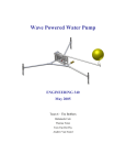
Four Post Lift
8,000 lbs. Capacity
INSTALLATION / OWNERS MANUAL
Read this manual thoroughly before installing, operating, or maintaining this lift. When done with
installation be sure to return documents to package and give all materials to lift owner/operator. When
installation is complete be sure to run lift up and down a few cycles with and without “typical” vehicle
loaded on lift.
PP8S
1
IN50011 Rev. B 03/03/2008
TABLE OF CONTENTS
•
•
•
•
•
•
•
•
•
•
•
•
•
•
•
IMPORTANT INFORMATION
OWNER / EMPLOYER RESPONSIBILITY
LOCKOUT / TAGOUT
SAFETY PROCEDURES
LIFT SPECIFICATIONS & FLOOR PLAN
TOOLS REQUIRED
INSTALLATION INSTRUCTIONS
CASTER KIT ASSEMBLY / INSTALLATION
FOUNDATION & ANCHORING REQUIREMENTS
OPERATION INSTRUCTIONS
PREVENTIVE MAINTENANCE SCHEDULE
TROUBLESHOOTING
CABLE INSPECTION GUIDE
ILLUSTRATED PARTS LIST
WARRANTY POLICY
pg 2
pg 3
pg 3
pg 4
pg 6
pg 7
pg 7
pg 11
pg 13
pg 15
pg 17
pg 19
pg 21
pg 27
pg 35
IMPORTANT INFORMATION
Four Post Lifts
1.
2.
3.
4.
5.
6.
7.
8.
Always inspect the lift for damage and make note of any damage on the bill of
lading.
In case of freight damage, call the truck line immediately and report the damage as
a freight claim.
Make sure you have extra help or heavy duty lifting equipment when unloading and
assembling the lift.
Please read the safety procedures and operating instructions in this manual before
operating lift. Keep this manual near lift at all times. Make sure all operators read
this manual.
The lift should be located on a relatively level floor of less than 3 degrees slope. If
slope is questionable, consider a survey of the site and/or the possibility of pouring
a new level concrete slab.
Make sure you have enough room to install the lock rods. You will need at least
9’ of clearance from the opposite end of the power unit end of the lift and 6’
at the power unit end. (See floor plan on page 6). The power unit may be
installed on the driver’s front or the passenger rear corner.
Never raise a car until you have double checked all bolts, nuts and hose fittings.
Always lower the lift to locks before going under the vehicle or storing another
vehicle underneath lift. Never allow anyone to go under the lift when raising or
lowering.
This is a vehicle lift installation/operation manual and no attempt is made or implied herein to
instruct the user in lifting methods particular to an individual application. Rather, the contents of
this manual are intended as a basis for operation and maintenance of the unit as it stands alone or
as it is intended and anticipated to be used in conjunction with other equipment.
Proper application of the equipment described herein is limited to the parameters detailed in the
specifications and the uses set forth in the descriptive passages. Any other proposed application
of this equipment should be documented and submitted in writing to the factory for examination.
The user assumes full responsibility for any equipment damage, personal injury, or alteration of
the equipment described in this manual or any subsequent damages.
PP8S
2
IN50011 Rev. B 03/03/2008
4 1/ 2"
81 1/ 2"
72 1/ 2"
4 1/ 2"
LIFT SPECIFICATIONS & FLOOR PLAN
151 1/ 2"
158"
169 1/ 2"
175 1/ 2"
207 1/ 2"
YOU WILL NEED A MIN. OF 6’
CLEARANCE IN FRONT TO
INSTALL HANDLE ROD
18 1/ 2"
38"
103 1/ 2"
100 3/ 4"
94"
83"
18 1/ 2"
YOU WILL NEED A MIN. OF
9’ CLEARANCE IN REAR
TO INSTALL “T” ROD
Technical Data
Lifting Height
Overall Length with Ramps
Overall Length without Ramps
Overall Width
Height Of Columns
Runway Width
Runway Height
Clearance Between Runways
Capacity
PP8S
3
72-1/2”
207-1/2”
175-1/2”
103-1/2”
81-1/2”
18-1/2”
4-1/2”
38”
8000 lbs.
IN50011 Rev. B 03/03/2008
TOOLS REQUIRED
•
•
•
•
•
•
Set of metric wrenches and/or sockets
Adjustable wrench
Locking pliers
25’ Tape measure
Step Ladder
*3 Gallons of Hydraulic Oil
*Recommended Oil: ISO 32 Light Hydraulic Oil
INSTALLATION INSTRUCTIONS
PP8S
4
IN50011 Rev. B 03/03/2008
PP8S
5
IN50011 Rev. B 03/03/2008
PP8S
6
IN50011 Rev. B 03/03/2008
PP8S
7
IN50011 Rev. B 03/03/2008
OPTIONAL CASTER KIT
1. Install caster wheels to caster frames as shown.
NOTE: Hitch Pin and Hairpin Clip will be used to attach casters to lift in following steps. DO
NOT Install at this time.
M10 x 1-3/8” Bolt
Ø10 Flat Washer
Hairpin Clip
Ø10 Flat Washer
Hitch Pin
Ø10 Lock Washer
M10 Nut
1. Raise lift 2' - 3' high.
2. Place caster assemblies under crossbeams as shown. Secure with Hitchpin and
Hairpin Clip.
3. Lower lift and the columns will automatically raise off the floor.
4.
5.
Lower Lift and weight of crossbeam
will automatically raise columns off
the ground.
Column
Crossbeam
Hitch Pin &
Hairpin Clip
Caster
PP8S
8
IN50011 Rev. B 03/03/2008
SPECIAL NOTE
This Lift does not require bolting to the floor
(BUT)
If you choose the option to anchor the Lift to the floor please follow
the detailed instructions and criteria below.
FOUNDATION and ANCHORING REQUIREMENTS
1. Concrete shall have compression strength of at least 3,000 PSI and a minimum
thickness of 4” in order to achieve a minimum anchor embedment of 3 ¼”.
NOTE: When using (¾” x 5 ½”) long anchors; if the top of the anchor exceeds 2
¼” above the floor grade, you DO NOT have enough embedment.
2. Maintain a 6” minimum distance from any slab edge or seam. Hole to hole
spacing should be a minimum 6 ½” in any direction. Hole depth should be a
minimum of 4”.
CAUTION!!
3. DO NOT install on asphalt or other similar unstable surface. Columns are
supported only by anchoring to floor.
4. Shim each column base as required until each column is plumb. If one column
has to be elevated to match the plane of the other column, full size base shim
plates should be used. Torque anchors to 85 ft-lbs. Shim thickness MUST NOT
exceed ½” when using the 5 ½” long anchors with the lift. Adjust the column
extensions plumb.
5. If anchors do not tighten to 85 ft-lbs. installation torque, replace the concrete
under each column base with a 4’ x 4’ x 6” thick 3,000 PSI minimum concrete
pad keyed under and flush with the top of existing floor. Allow concrete to cure
before installing lifts and anchors (typically 2 to 3 weeks).
PP8S
9
IN50011 Rev. B 03/03/2008
ANCHORING TIP INSTRUCTIONS
CAUTION!!
Anchors must be at least 6” from the edge of the slab or any seam.
1. Use a concrete hammer drill with a carbide tip, solid drill bit the same diameter
as the anchor, ¾”. (.775 to .787 inches diameter). Do not use excessively worn
bits or bits which have been incorrectly sharpened.
2. Keep the drill in a perpendicular line while drilling.
3. Let the drill do the work. Do not apply excessive pressure. Lift the drill up and
down occasionally to remove residue to reduce binding.
4. Drill the hole to depth equal to the length of anchor. Note: Drilling thru concrete
(recommended) will allow the anchor to be driven thru the bottom of foundation
if the threads are damaged or if the lift will need to be relocated.
5. For better holding power blow dust from the hole.
6. Place a flat washer and hex nut over threaded end of anchor, leaving
approximately ½ inch of thread exposed carefully tap anchor. Do not damage
threads. Tap anchor into the concrete until nut and flat washer are against base
plate. Do not use an impact wrench to tighten! Tighten the nut, two or three turns
on average concrete (28-day cure). If the concrete is very hard only one or two
turns may be required. Check each anchor bolt with torque wrench set to 85 foot
pounds.
PP8S
10
IN50011 Rev. B 03/03/2008
CAUTION NOTE !!
LUBRICATE ALL CABLE SHEAVES, BEARINGS, AND SHAFTS WITH GREASE PRIOR TO
OPERATING THE LIFT. LUBRICATE ALL ON AN ANNUAL BASIS.
Motors and all electrical components are not sealed against the weather and moisture. Install
this lift in a protected indoor location. Failure by the owner to provide the recommended
shelter could result in unsatisfactory lift performance, property damage, or personal injury.
OWNER / EMPLOYER RESPONSIBILITIES
The Owner / Employer:
• Shall ensure that lift operators are qualified and that they are trained in the safe use and operation
of the lift using the manufacturer’s operating instructions; ALI/SM01-1, ALI Lifting it Right safety
manual; ALI/ST-90 ALI Safety Tips card; ANSI/ALI ALOIM-2000, American National Standard for
Automotive Lifts-Safety Requirements for Operation, Inspection and Maintenance; ALI/WL Series,
ALI Uniform Warning Label Decals/Placards; and in the case of frame engaging lifts, ALI/LP-GUIDE,
Vehicle Lifting Points/Quick Reference Guide for Frame Engaging Lifts.
• Shall establish procedures to periodically inspect the lift in accordance with the lift manufacturer’s
instructions or ANSI/ALI ALOIM-2000, American National Standard for Automotive Lifts-Safety
Requirements for Operation, Inspection and Maintenance; and The Employer Shall ensure that lift
inspectors are qualified and that they are adequately trained in the inspection of the lift.
• Shall establish procedures to periodically maintain the lift in accordance with the lift manufacturer’s
instructions or ANSI/ALI ALOIM-2000, American National Standard for Automotive Lifts-Safety
Requirements for Operation, Inspection and Maintenance; and The Employer Shall ensure that lift
maintenance personnel are qualified and that they are adequately trained in the maintenance of the
lift.
• Shall maintain the periodic inspection and maintenance records recommended by the manufacturer
or ANSI/ALI ALOIM-2000, American National Standard for Automotive Lifts-Safety Requirements for
Operation, Inspection and Maintenance.
• Shall display the lift manufacturer’s operating instructions; ALI/SM 93-1, ALI Lifting it Right safety
manual; ALI/ST-90 ALI Safety Tips card; ANSI/ALI ALOIM-2000, American National Standard for
Automotive Lifts-Safety Requirements for Operation, Inspection and Maintenance; and in the case
of frame engaging lifts, ALI/LP-GUIDE, Vehicle Lifting Points/Quick Reference Guide for Frame
Engaging Lifts; in a conspicuous location in the lift area convenient to the operator.
• Shall not modify the lift in any manner without the prior written consent of the manufacturer.
• Shall provide necessary lockout/tagout means for energy sources per ANSI Z244.1-1982 (R1993),
Safety Requirements for the Lockout/Tagout of Energy Sources, before beginning any lift repairs.
Lift Lockout/Tagout Procedure
Purpose
This procedure establishes the minimum requirements for the lockout of energy that could cause
injury to personnel by the operation of lifts in need of repair or being serviced. All employees shall
comply with this procedure.
PP8S
11
IN50011 Rev. B 03/03/2008
Responsibility
The responsibility for assuring that this procedure is followed is binding upon all employees and
service personnel from outside service companies (i.e., Authorized Rotary Installers, contactors, etc.).
All employees shall be instructed in the safety significance of the lockout procedure by the facility
owner/manager. Each new or transferred employee along with visiting outside service personnel shall
be instructed by the owner/manager (or assigned designee) in the purpose and use of the lockout
procedure.
Preparation
Employees authorized to perform lockout shall ensure that the appropriate energy isolating device
(i.e., circuit breaker, fuse, disconnect, etc.) is identified for the lift being locked out. Other such devices
for other equipment may be located in close proximity of the appropriate energy isolating device. If the
identity of the device is in question, see the shop supervisor for resolution. Assure that proper
authorization is received prior to performing the lockout procedure.
Sequence of Lockout Procedure
1) Notify all affected employees that a lockout is being performed and the reason for it.
2) Unload the subject lift. Shut it down and assure the disconnect switch is “OFF” if one is
provided on the lift.
3) The authorized lockout person operates the main energy isolation device removing power to
the subject lift.
;
If this is a lockable device, the authorized lockout person places the assigned padlock
on the device to prevent its unintentional reactivation. An appropriate tag is applied
stating the person’s name, at least 3” x 6” in size, an easily noticeably color, and states
not to operate device or remove tag.
;
If this device is a non-lockable circuit breaker or fuse, replace with a “dummy” device
and tag it appropriately as mentioned above.
4) Attempt to operate lift to assure the lockout is working. Be sure to return any switches to the
“OFF” position.
5) The equipment is now locked out and ready for the required maintenance or service.
Restoring Equipment to Service
1) Assure the work on the lift is complete and the area is clear of tools, vehicles, and
personnel.
2) At this point, the authorized person can remove the lock (or dummy circuit breaker or fuse)
& tag and activate the energy isolating device so that the lift may again be placed into
operation.
Rules for Using Lockout Procedure
Use the Lockout Procedure whenever the lift is being repaired or serviced, waiting for repair when
current operation could cause possible injury to personnel, or for any other situation when
unintentional operation could injure personnel. No attempt shall be made to operate the lift when the
energy isolating device is locked out.
Operating Conditions
Lift is not intended for outdoor use and has an operating ambient temperature range
of 41º-104ºF (5º-40ºC).
PP8S
12
IN50011 Rev. B 03/03/2008
SAFETY PROCEDURES
•
•
•
•
•
•
•
•
•
Never allow unauthorized persons to operate lift. Thoroughly train new employees in
the use and care of lift.
Caution - the power unit operates at high pressure.
Remove passengers before raising vehicle.
Prohibit unauthorized persons from being in shop area while lift is in use.
Total lift capacity is 8,000-lbs. Do not exceed this capacity.
Prior to lifting vehicle, walk around the lift and check for any objects that might
interfere with the operation of lift and safety latches; tools, air hoses, shop equipment.
When approaching the lift with a vehicle, make sure to center the vehicle between the
columns. Slowly drive the vehicle up with some one outside the vehicle guiding the
driver.
Prior to lowering vehicle, walk around the lift and check for any objects that might
interfere with the operation of lift and safety latches; tools, air hoses, shop equipment.
Slowly drive the vehicle on and off of the lift. Have some one outside the vehicle guide
the driver.
OPERATION INSTRUCTIONS
NOTE: ALWAYS CHOCK WHEELS AND SET PARKING BRAKE BEFORE LIFTING
VEHICLE!
Only authorized personnel are to operate lift. Read Operating and safety procedures
Manual completely before operating lift.
• Properly maintain and inspect lift in accordance to owner' manual.
• Do not operate a lift that is damaged or in need of repair.
• Allow only authorized personnel in the lift bay.
• Stay clear of lift when raising or lowering (no riders).
• Keep hands and feet away from pinch points at all times.
• Never override the lift operating and safety controls.
• If a vehicle is suspected of falling, clear area immediately.
• Do not rock vehicle while positioned on lift.
• Always use safety jack stands when removing or installing heavy components.
Vehicle Loading:
• Position vehicle on lift runways by having another person guide you onto the runways.
Check for proper weight distribution (center of gravity should be evenly distributed
between columns).
• Set vehicle parking brake and chock tires to prevent vehicle movement.
• Use caution before lifting pickup trucks, suv's and other vehicles. The individual axle
weight capacity should not exceed 1/2 of lift capacity.
• Make sure vehicle is neither front nor rear heavy.
Raising Lift:
• Push up switch to raise lift until platform runways clear floor.
• Stop and check for vehicle movement and vehicle weight distribution. If secure raise
to desired height.
PP8S
13
IN50011 Rev. B 03/03/2008
•
•
Always lower the lift to the nearest lock position by pressing the lower lever to relieve
the hydraulic pressure and let the latch set tight in a lock position.
Never work under a lift that is not in the locked position.
Lowering Lift:
• Clear all obstacles from under lift and vehicle, and ensure only lift operator is in the lift
area.
• Stay clear of lift and raise the lift off the safety locks.
• Pull safety latch releases and press the lower lever to begin descent.
• Ensure lift is fully lowered, and having another person guide you, carefully unload the
lift by driving off of the lift runways.
CAUTION
PAY ATTENTION TO THE LOWERING SPEED OF ALL FOUR CORNERS. MAKE SURE
THEY ARE MOVING DOWN AT THE SAME SPEED. STOP LOWERING THE LIFT BY
RELEASING THE LOWERING LEVER ON THE POWER UNIT AND MOVING THE LOCK
LEVER TO THE LOCK POSITION IF ANY CORNER STOPS MOVING OR IS SLOWER IN
DESCENT. ALWAYS LOCK THE LIFT BEFORE GOING UNDER THE VEHICLE. NEVER
ALLOW ANYONE TO GO UNDER THE LIFT WHEN RAISING OR LOWERING.
NOTE: It is normal for an empty lift to lower slowly - it may be necessary to add weight.
PP8S
14
IN50011 Rev. B 03/03/2008
Read and heed all WARNING, CAUTION and SAFETY INSTRUCTION labels on lift.
PP8S
15
IN50011 Rev. B 03/03/2008
PREVENTIVE MAINTENANCE SCHEDULE
The periodic Preventive Maintenance Schedule given is the suggested minimum
requirements and minimum intervals; accumulated hours or monthly period, which ever
comes sooner.
Periodic maintenance is to be performed on a daily, weekly, and yearly basis as given in the
following paragraphs.
WARNING!!
Occupational Safety and Health Administration (OSHA) and the American National
Standards Institute (ANSI) requires users to inspect lifting equipment at the start of
every shift. These and other periodic inspections are the responsibility of the user.
Failure to perform the daily pre-operational check can result in expensive property
damage, lost production time, serious personal injury, and even death. The safety
latch system must be checked and working properly before the lift is put to use.
Failure to heed this warning can result in death or serious injury, or damage to
equipment. If you hear a noise not associated with normal lift operation, or, if there is
any indications of impending lift failure - CEASE OPERATION IMMEDIATELY! - Inspect,
correct and/or replace parts as required.
Daily Pre-Operation Check (8-Hours)
•
•
•
•
•
•
•
•
•
•
Check safety lock audibly and visually while in operation
Check safety latches for free movement and full engagement with rack.
Check hydraulic connections, and hoses for leakage.
Check cables connections bends, cracks-and for loose fittings.
Check for frayed cables in both raised and lowered position.
Check snap rings at all rollers and sheaves.
Check bolts, nuts, and screws and tighten if needed.
Check wiring & switches for damage.
Check floor for stress cracks near columns.
Check Lubrications on cable sheaves and shafts.
Weekly Maintenance (every 40-Hours)
•
•
•
•
•
PP8S
IF LIFT IS ANCHORED TO FLOOR - Check anchor bolts torque to 50 ft-lbs for the ¾
in. anchor bolts. Do not use an impact wrench to tighten anchor bolts.
Check floor for stress cracks near columns
Check hydraulic oil level.
Check and tighten bolts, nuts, and screws.
Check all cable sheaves/assembly for free movement or excessive wear on cable
sheave shaft.
16
IN50011 Rev. B 03/03/2008
Yearly Maintenance
•
•
•
Lubricate the cable sheave shaft by using grease gun at lease once a year after the
lift is in service.
Check for excessive wear of cable. Replace them if necessary.
Change the hydraulic fluid - good maintenance procedure makes it mandatory to keep
hydraulic fluid clean. No hard fast rules can be established; - operating temperature,
type of service, contamination levels, filtration, and chemical composition of fluid
should be considered. If operating in dusty environment shorter interval may be
required.
Special Maintenance Tasks
NOTE: The following items should only be performed by a trained maintenance expert:
•
•
•
•
•
Replacement of hydraulic hoses.
Replacement of cables and sheaves.
Replacement or rebuilding air and hydraulic cylinders as required.
Replacement or rebuilding pumps / motors as required.
Checking of hydraulic cylinder rod and rod end (threads) for deformation or
damage.
CAUTION!!
Relocating or changing components may cause problems. Each component in the
system must be compatible; an undersized or restricted line will cause a drop in
pressure. All valve, pump, and hose connections should be sealed and/or capped until
just prior to use. Air hoses can be used to clean fittings and other components.
However, the air supply must be filtered and dry to prevent contamination. Most
important is cleanliness; Contamination is the most frequent cause of malfunction or
failure of hydraulic equipment.
PP8S
17
IN50011 Rev. B 03/03/2008
TROUBLESHOOTING
The common problems that may be encountered and their probable causes are
covered in the following paragraphs:
•
Motor Does Not Operate
Failure of the motor to operate is normally caused by one of the following:
1. Breaker or fuse blown.
2. Faulty wiring connections; call electrician.
3. Defective up button; call electrician for service.
•
Motor Functions but Lift Will Not Rise
If the motor is functioning, but the lift will not rise do the following in the order given:
1. A piece of trash is under check valve. Push handle down and push the up button at the
same time. Hold for 10-15 seconds. This should flush the system.
2. Check the clearance between the plunger valve of the lowering handle. There should
be 1/16” clearance.
3. Remove the check valve cover and clean ball and seat.
WARNING!!
Failure to properly relieve pressure in the following step can cause injury to
personnel. This lift uses ISO Grade 32 or other good grade non-detergent hydraulic
oil at a high hydraulic pressure. Be familiar with its toxicological properties,
precautionary measures to take, and first aid measures as stated in the Safety
Summary before performing any maintenance with the hydraulic system.
4. Oil level too low. Oil level should be just under the vent cap port when the lift is down.
Relieve all hydraulic pressure and add oil as required.
•
Oil Blows out Breather of Power Unit
If oil blows out of the breather of the power unit, take the following actions:
1. Oil reservoir overfilled. Relieve all pressure and siphon out hydraulic fluid until at a
proper level
2. Lift lowered too quickly while under a heavy load. Lower the lift slowly under heavy
loads.
PP8S
18
IN50011 Rev. B 03/03/2008
•
Motor Hums and Will Not Run
If the motor hums but fails to run, take the following actions:
1. Lift overloaded. Remove excessive weight from lift
WARNING!!
The voltages used in the lift can cause death or injury to personnel. In the following
steps, make sure that a qualified electrician is used to perform maintenance
2. Faulty wiring..….... Call electrician
3. Bad capacitor..….. Call electrician
4. Low voltage........... Call electrician
•
Lift Jerks Going Up and Down
1. If the lift jerks while going up and down, it is usually a sign of air in the hydraulic system.
Raise lift all the way to top and return to floor. Repeat 4-6 times. Do not let this
overheat power unit.
•
Oil Leaks
Oil leak causes at the power unit and cylinders are normally caused by the following:
1. Power unit: if the power unit leaks hydraulic oil around the tank-mounting flange check
the oil level in the tank. The level should be two inches below the flange of the tank. A
screwdriver can be used as a “dipstick”.
2. Cylinder - Piston Rod: the rod seal of the cylinder is out. Rebuild or replace the
cylinder.
3. Cylinder - Vent: the piston seal of the cylinder is out. Rebuild or replace the cylinder.
•
Lift makes excessive noise / vibrates
Excessive noise from the lift is normally caused by the following:
1. Cross beam ends are rubbing the columns. Readjustment needed.
2. Cylinder too tight, load lift half capacity and cycle up and down a few times to break in.
Lift cylinder should quiet down with use. If not contact your Direct Lift Distributor to
purchase an Oil Additive.
3. May have excessive wear on cable sheaves or shafts. Replace them.
PP8S
19
IN50011 Rev. B 03/03/2008
Cable Inspection Guide
Maximum Allowable Cable Necking
Nom. Cable Diameters Max. Reduction in Diameter
Up to 5/16”
1/64”
3/8” to 1/2”
1/32”
9/16” to 3/4”
3/64”
7/8” to 1-1/8”
1/16”
1-1/4” to 1-1/2”
3/32”
Typical Good Cable
Cable With Broken Wires
Cable With Severe Corrosion
Cable With Necking
Daily Inspection & Maintenance
1. Cleanliness: Cables, Columns, Runways and other lift parts should be kept free of
corrosive agents, solvents, and road salts. If such agents are spilled or splashed on any lift
component, immediately rinse thoroughly with water and wipe down with a clean rag. Spray
wire rope cables as required with Penetrating Oil and wipe down.
Failure to keep lift free of corrosive agents and solvents will lead to reduced component
service life, cable failure, etc., which could result in property damage and/or personal injury.
2. Fasteners: Check all the attaching bolts and nuts for tightness.
PP8S
20
IN50011 Rev. B 03/03/2008
3. Cables: Check wire rope cables for wear or damage. Any cable with broken wires,
severe corrosion, excessive stretch, deformed strands, variations in diameter (necking), or
any change from its normal appearance, must be replaced. If any cable is found to be in
need of replacement, the entire cable set must be replaced immediately. Refer to Þgures
below.
4. Sheaves: Check sheaves (pulleys) for wear or damage, i.e. wobble (tilt), cracks, loose on
pin, or excessive noise during operation.
5. Sheave Pins: Check for loose or missing sheave (pulley) pins.
6. Locking Latches and Slack Cable Devices: Watch locking latches and slack cable devices
during lift operation to ensure that latches work properly and line up with slots in latch plate
located in columns.
Monthly Inspection & Maintenance
1. Cables
1.1 Clean wire rope cables with lift in both lowered and raised position by spraying with
Penetrating Oil and wiping the cable down.
1.2 Adjust cables using procedures on following pages.
2. Slack Cable Device: Inspect slack cable devices using procedure on page 5.
3. Column Anchor Bolts: Check column anchor bolts for tightness. Re-torque anchors bolts
to 65 ft/lbs. If anchors do not tighten to the required installation torque, replace concrete
under each column base per installation instructions. Let concrete cure before installing lifts
and anchors.
4. Columns: Look for corrosion, giving special attention to the area at the base of the
column. Check severely corroded areas by pecking with an awl or welder’s chipping
hammer. If column is corroded through at any point it must be replaced immediately. If not
corroded through, remove old paint and rust scale, then coat with a high quality corrosion
resistant paint.
A thorough inspection of the lifting system must be performed quarterly by qualiÞed
lift service personnel; more frequently (monthly) under extreme service conditions such as
outside installations or high usage (10 or more cycles per day, etc.).
Quarterly Inspection & Maintenance
1. Cables
1.1 Inspect cables in both lowered and raised position. The cables may also be viewed
through various inspection holes and openings in yokes and runways. Check all the
following:
a. That cables have no broken wires visible, reference Daily Inspection & Maintenance.
PP8S
21
IN50011 Rev. B 03/03/2008
b. That cables are free of severe corrosion and pitting, reference Daily Inspection &
Maintenance. A light surface corrosion on exposed outer wires is normal. Penetrating
Oil should be applied during monthly periodic inspection.
c. That there are no areas on the cable that have a greatly reduced diameter or
“necking”, reference Daily Inspection & Maintenance. When any cable is found with
excessive necking, all cables must be replaced immediately.
d. That cables do not have excessive stretch. It is normal for new cable to require
adjustment during “break-in”, after which small periodic adjustments may be required.
However, if a cable that has been in service for 6 months should suddenly require
frequent adjustments or has used all the cable adjustment available, all cables must
be replaced immediately.
e. If any cable is found to be in need of replacement, the entire cable set must be
replaced immediately.
f. Cables are expendable items and should be replaced as a set every 20,000 cycles
(estimated) or every 6 years, unless earlier replacement is indicated during inspection.
2. Sheaves and Pins
Inspect sheaves and pins in yokes and runways. Sheaves are expendable items. Sheaves
and pins should be replaced when worn. Use of sheaves and pins with excessive wear will
lead to reduced service life of cables.
2.1 Inspect sheaves (pulleys) in yoke ends with lift in lowered position or resting on the
locking latches.
a. Hold lowering handle down and pull on cable in column to create slack in cables.
b. Check for excessive side to side wobble. Grasp rim of sheave and attempt to wobble
(tilt) side to side. If sheaves wobble (tilt) more than 3/16” (4.8 mm) side to side or
move up and down on shaft more than 1/32” (0.8 mm), the sheave and pin (shaft)
should be replaced, refer Þgures below.
c. Check sheaves and replace if cracks are found.
d. Check for ease of rotation. If sheaves do not turn freely, the sheave and sheave pin
should be removed, inspected, lubricated, and reinstalled or replaced.
PP8S
22
IN50011 Rev. B 03/03/2008
2.2 Fully raise lift. Inspect sheaves (pulleys) in runway ends with lift in raised position.
a. Visually inspect alignment of sheaves, see Þgure above. Misalignment of sheave(s)
indicates excessive wear; the sheave(s) and sheave pin should be removed and
inspected. Replace as required.
b. Hold lowering handle down to lower lift onto latches. Pull on cables under runway to
create cable slack.
c. Check for excessive side to side wobble. Grasp rim of sheave and attempt to wobble
(tilt) side to side, refer to Þgures above. If sheaves wobble (tilt) more than 1/16” (1.6
mm) side to side, or move in and out more than 1/32” (0.8 mm), the sheave and
sheave pin (shaft) should be replaced, refer to Þgures above.
3. Hydraulic Cylinder
Inspect the hydraulic cylinder mounting to the runway. Inspect cylinder and hydraulic hoses
for leaks. Repair or replace as required.
PP8S
23
IN50011 Rev. B 03/03/2008
1 Check and tighten the hydraulic cylinder rod nuts holding the cable pull bar.
4. TRACKS for Rolling Jack and Oil Drain Pan
Inspect rolling jack/oil drain pan tracks for cleanliness, corrosion, excessive wear or damage.
Clean dirty tracks.
Worn or damaged tracks must be repaired immediately.
Failure to do so will lead to reduced service life which could result in property damage and/or
personal injury.
5. Latch Inspection and Adjustment
Check locking latches for proper operation. Inspect for worn or missing parts. Replace worn
or damaged parts and adjust as required.
1. Latches
Check latch operation on all four corners.
2. Latch and Latch Bar Line-Up
Observe locking latches during lift operation to ensure that all latches line up with slots in
latch bar located in all four columns. If not, relocate and/or re-shim columns.
1. Check slack cable devices for proper operation. Inspect for worn or missing parts.
Replace worn or damaged parts as required.
2. Observe both locking latches and slack cable devices during lift operation to ensure that
all latches line up with slots in latch bar located in all four columns.
Cable Adjustment
1. Initial Adjustment
Adjust cable with lift fully lowered. Loosen jam nut and tighten nut on cable stud on top of
column until yoke end is raised 1/4” (6.4 mm) and back off nut one turn. Retighten jam nut.
Repeat for all four cables.
2. Final Adjustment
a. Load a typical vehicle on lift.
b. Raise lift as high as it will travel (full height). You should hear the locking latches click
through all latch slots simultaneously.
c. Lower lift onto top latch position.
d. Check clearance:
e. Starting with the right front column, use a straight edge to mark the position of the
yoke bottom on the column.
f. Raise lift to full height again. Mark second position. If gap between two marks is less
than 2”, adjust locking latch bar to reach clearance of 2”. Repeat for the other three
columns.
g. Adjust locking latch bar adjusting nut so that the bottom of the topmost latch bar slot is
PP8S
24
IN50011 Rev. B 03/03/2008
at least 2” below locking latch. After adjustment, tighten jam nut underneath column
top plate, Fig. 11.
h. If entire 2” clearance cannot be attained by adjusting the locking latch bar, adjust the
cable. Turn cable adjusting nut to raise the locking latch 2” above bottom of latch bar
slot. Tighten cable jam nut.
i. Lower lift and remove vehicle.
j. Raise the lift to full height. LISTEN and WATCH as the Þrst locking latch clicks into
place. Synchronize the other three columns with this column by adjusting their cables
so all four latches click at same time. Tighten jam nuts.
When making changes to adjustment nuts on cable end or latch bar stud, always leave at
least two threads showing between nut and stud end.
Latches may not click in at the same time when vehicle is being raised. They should be close.
Be sure all four corners have passed the locking latch bar slot before lowering lift on locking
latches
PP8S
25
IN50011 Rev. B 03/03/2008
FOUR POST 8K ILLUSTRATED PARTS LIST
4
30
29
36
35
5
4 2
23 2
3
2
24
25
34
4
23 2
15
22 6 18
22
26
22
15
22
2
25
3
4
13 1
3 9
37
10
9
18 1 2
9
11
25
24
23
17
1
8
12
0
20 2
53
7
33
16
4
2
IN50011 Rev. B 03/03/2008
26
PP8S
32
90
28
27
5
2
GENERAL ILLUSTRATED PARTS LIST – FIGURE #1
20
19
18
71
66
67
47
57
20
53
62
56
58
31
72
59
55
60
61
87
89
62
38
6
87
89
62
38
62
63
64
69
60
59
65
61
67
66
68
31
IN50011 Rev. B 03/03/2008
27
PP8S
31
70
20
19
54
31
CROSSBEAM ASSEMBLY – FIGURE # 2
39
90
48
47
38
38
49
50
38
9
41
46
45
51
47
38
CABLE COMPONENTS & ROUTING – FIGURE # 3
PP8S
28
IN50011 Rev. B 03/03/2008
73
93
19
20
55
73
75
38
75
38
77
38
93
19
20
55
33
76
RUNWAY AND SHEAVE COMPONENTS - FIGURE # 4
PP8S
29
IN50011 Rev. B 03/03/2008
84
A
83
85
A
70
78
78
80
30
B
78
82
81
78
85
86
86
87
79
85
83
79
87
88
91
B
84
85
84
80
83
64
SAFETY LATCH & LINKAGE COMPONENTS – FIGURE # 5
PP8S
30
IN50011 Rev. B 03/03/2008
11 10
9
12
33
7
17
16
37
HYDRAULIC & CYLINDER COMPONENTS - FIGURE # 6
PP8S PARTS LIST
Items
PP8S
Drawing #
Description
QTY
1
PP8S-1000
Column Weldment A
1
2
PP8S-1100
Column Weldment B
3
3
DP8-1200
Column Top Caps
2
4
DP8-1200DC
Column Top Caps
2
5
PP8S-1210
Latchbar Weldment
4
6
DP8-2100
Crossbeam Weldment
2
7
P3543
Power Unit
1
8
DP8-5000
Ramp Weldment
2
9
YG02-9100G
Hydraulic Cylinder
1
10
PP7-9802-2
Pipe Fitting
1
11
PP7-9200
Throttle
1
12
1WB-04
Hydraulic Hose
1
13
H4D-5005
Hydraulic Cylinder Pin
1
14
B52-5×60
Cotter Pin Ø5×60
2
15
H4D-5000
Link Frame
4
16
1WB-05
Hydraulic Hose
1
31
IN50011 Rev. B 03/03/2008
PP8S
17
SW-002(304009053YZ)
90 Degree Fitting
1
18
B30-8
Nut M8
10
19
B40-8
Lock Washer Ø8
24
20
B41-8
Flat Washer Ø8
60
22
B10-18×100
Hex Head Bolt M18×100
8
23
B41-18
Flat Washer Ø18
8
24
B40-18
Lock Washer Ø18
8
25
B30-18
Nut M18
8
26
H4D-7001-07
Bolts M8×50
2
27
B10-12×30
Hex Head Bolt M12×30
16
28
B41-12
Flat Washer Ø12
32
29
B40-12
Lock Washer Ø12
16
30
B30-12
Nut M12
18
31
DP8-2013
Flat Washer Ø20
8
32
B30-20
Nut M20
4
33
PP8S-3100
Runway Weldment, Non-Power Unit Side
1
34
DP8-3200
Runway Weldment, Power Unit Side
1
35
H4D-5001
Car Stop Plates
4
36
NH4D-3303
Nut
4
37
H4D-Y003
90 Degree Fitting
1
38
DP8-2012
Cable Pulley
10
39
B33-3/4"-16
Nylon Lock Nut 3/4"-16
4
41
B33-24×2
Nylon Lock Nut M24×2
1
45
H4D-5003
Cable Lock PlateA
1
46
H4D-5004
Cable Lock PlateB
1
47
DP8-2004
Small Cable Pulley
4
48
PP7-2004
Cable
1
49
PP7-2003
Cable
1
50
PP7-2002
Cable
1
51
PP7-2001
Cable
1
53
B10-8×35
Hex Head Bolt M8×35
36
54
B10-8×20
Hex Head Bolt M8×20
8
55
NH4D-2005
Lock Plate
8
56
DP8-2003
Slider
8
57
DP8-2009
Shaft
4
58
DP8-2001
Pulley Cover
2
59
B22-8×10
Set Screw M8×10
4
60
DP8-2007
Bushings
4
61
DP8-2006
Cable Pulley Pin
4
62
DP8-2014
Flat Washer Ø24C Level
12
32
IN50011 Rev. B 03/03/2008
63
NH4D-1011
Spring
8
64
DP8-2011DC
Work Lock
2
65
NH4D-1004
Spring
2
66
DP8-2008
Spacer
4
67
DP8-2005
Lock Shaft
4
68
DP8-2010DC
Safty Lock
2
69
DP8-2002
Pulley Cover
2
70
DP8-2011
Work Lock
2
71
NH4D-1004DC
Spring
2
72
DP8-2010
Safty Lock
2
73
H4D-5007
Plastic Plate
2
75
PP7-3001
Cable Pulley Shaft
4
76
PP7-3003
Spacer
2
77
PP7-3002
Spacer
2
78
DP8-4301
Long Rod
2
79
DP8-4401
Short Rod
2
80
DP8-4210
Joy Stick B
1
81
H4D-7000-03
Coupler
1
82
DP8-4110
Joy Stick A
1
83
B72-6
Bearing M6
8
84
B33-6
Nylon Lock Nut M6
8
85
B30-6
Nut M6
8
86
B10-6×30
Hex Head Bolt M6×30
4
87
B41-6
Flat Washer Ø6
12
88
B84-35
Plastic Knod For Handle Ø35×M10
1
89
B23-6×10
Discal Head Screw M6×10
4
90
B41-20
Flat Washer Ø20
8
91
H4D-7000-05
Steel Spacer
2
92
30400-1999
Washer
4
93
B10-8×16
Hex Head Bolt M8×16
8
Optional Accessories for PP8S
PP8S
PP8S-2000CK
Caster Kit - Assembly
4
PP8S-2000
Caster Kit - Frame Weldment
4
B80-6×2
Caster Kit - Caster Wheel Assembly 6"×2"
4
PP8S-2100
Caster Kit - Hitch Pin
4
H4D-5006-03
Caster Kit - Hairpin Clip
4
B30-10
Hex Nut - M10
16
B40-10
Lock Washer - Ø10
16
B41-10
Flat Washer - Ø10
32
33
IN50011 Rev. B 03/03/2008
PP8S
B10-10×35
Hex Bolt - M10×35
16
DP7PNBKD-DT
Drip Tray
3
H4D-6000
Jack Tray / Tool Box
1
34
IN50011 Rev. B 03/03/2008