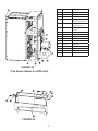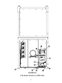
1
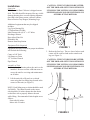
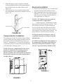
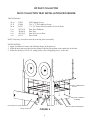
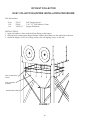
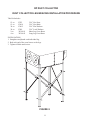
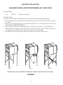
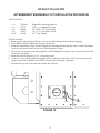
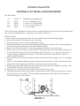
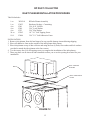
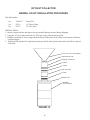
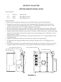
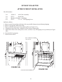
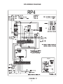
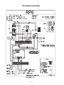
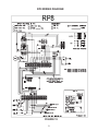
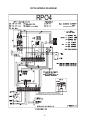
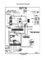
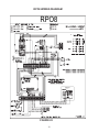
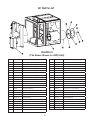
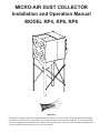
MICRO-AIR DUST COLLECTOR
Installation and Operation Manual
MODEL RP4, RP6, RP8
Important:
This manual contains specific cautionary statements relative to worker safety. Read this manual thoroughly
and follow as directed. It is impossible to list all the hazards of dust control equipment. It is important that
use of the equipment be discussed with a Micro Air Representative. Persons involved with the equipment or
systems should be instructed to operate in a safe manner.
1
TABLE OF CONTENTS
CAUTIONS
3
SPECIFICATIONS
4
INSTALLATION
INSPECTION
EQUIPMENT / TOOLS REQUIRED
ASSEMBLY OF UNIT
COMPRESSED AIR INTALLATION
ELECTRICAL INSTALLATION
UNITS INSTALLED OUTDOORS
UNIT OPERATION
CARTRIDGE CLEANING OPERATION
ROTO-PULSE CLEANING TIMER ADJUSTMENTS
AFTER-PULSE CLEANING TIMER ADJUSTMENTS
5
5
5
6
6
7
7
7
8
8
OPTIONAL COMPONENT INSTALLATION
DUST COLLECTION TRAY INSTALLATION PROCEDURE
DUST COLLECTION HOPPER INSTALLATION PROCEDURE
DUST COLLECTOR LEF BRACING INSTALLATION PROCEDURE
SILENCER INSTALLATION PROCEDURE (64” LEGS ONLY)
MAGNEHELIC KIT INSTALLATION PROCEDURE
PHOTOHELIC KIT INSTALLATION PROCEDURE
INLET PLENUM INSTALLATION PROCEDURE
BARREL LID KIT INSTALLATION PROCEDURE
MOTOR SHROUD INSTALLATION
AFTER FILTER KIT INSTALLATION
9
10
11
12
13
14
15
16
17
18
WIRING DIAGRAMS
RP4 WIRING DIAGRAM
RP6 WIRING DIAGRAM
RP8 WIRING DIAGRAM
RPO4 WIRING DIAGRAM
RPO6 WIRING DIAGRAM
RPO8 WIRIING DIAGRAM
19
20
21
22
23
24
RP PARTS LIST
25
2
Cautions:
All wiring must be done in accordance with
applicable National, State, and local electrical
code. MicroAir does not determine what is
acceptable in any local jurisdiction and cannot
be held responsible for wiring that does not
meet local codes.
Avoid mixing combustible materials, such
as buffing lint, paper, wood, aluminum, and
magnesium dust, and with dust generated from
grinding ferrous metals due to the potential fire
hazard caused by sparks in the dust collector.
Under no conditions should the persons operating
the dust collector be allowed to put cigarettes or
any burning object into the hood or ducting of any
dust collector system.
Improper installation or operation of this
equipment can cause damage to equipment
and / or injury to personell. The installation/
operation manual must be read and followed in
its entirety.
All users of Micro-Air Dust Collector Equipment
should comply with all National and Local Fire
Codes and/or other appropriate codes when
determinimg the location and operation of dust
control equipment.
Many of the processes outlined in this manual
will expose the installer to circuits powered by
high voltage. This installation is recommended
for professional electricians or MicroAir trained
personnel.
When dust collectors are used to collect flammable
or explosive dusts, the dust collector should be
located outside the building. Also, an installer
of fire extinguisher equipment, familiar with this
type of fire hazard and local fire codes, should be
consulted for recommendations and installation
of the proper fire extinguishing equipment. Dust
collectors do not contain fire extinguishing
equipment.
Explosion relief vents are required on some
applications. Consult with an insurance
underwriter or a NFPA manual to determine proper
vent size ratio. Vents installed on dust control
equipment within a building, must be vented to
the outside to minimize changes of secondary
explosion. Consult the proper authority having
jurisdiction to determine proper method of venting.
Dust collectors do not contain Explosion Relief
Vents, except on special order.
3
MICRO-AIR DUST COLLECTOR SPECIFICATIONS
Input Voltage:
208-230/460VAC 60 Hz 3-Phase
Maximum Current:
5HP:
208-230V
460V
13.2 - 12.0 amps
6.0 amps
7-1/2HP:
208-230V
460V
21.0-18.8 amps
9.4 amps
10HP:
208-230V
460V
26.4-24.0 amps
12.0 amps
Motor:
5HP, 3-Phase TEFC Motor, 3450 RPM
7-1/2HP, 3-Phase TEFC Motor, 3450 RPM
10HP, 3-Phase TEFC Motor, 3450 RPM
Cabinet Dimensions:
RP4, RPO4
129” H x 42” W x 62” D
RP6, RPO6
151” H x 42” W x 62” D
RP8, RPO8
171” H x 42” W x 62” D
Weight:
RP4, RPO4
RP6, RPO6
RP8, RPO8
1315 lb.
1460 lb.
1850 lb.
Filter Area:
RP4, RPO4
RP4, RPO4
RP4, RPO4
936 square feet
1404 square feet
1872 square feet
Dust Trap Capacity (Optional):
2.8 cubic feet total
Air Recuirements:
• 1.1 SCFM at 80 psi per second of cleaning pulse: 2.7 scfm total.
• Minimum air line 3/4 inch at 80 psi maximum.
• 3/4” NPT Female fitting is standard for shp air attachment.
• Clean, dry, compressed air at the correct pressure is required for the cleaning system to operate correctly
• It is recommended that a pressure regulator and coalescing filter be installed between the copressed air
source and the inlet to the dust collector.
4
CAUTION: THE UNIT SHOULD BE LIFTED
OFF THE SKID AND SET INTO POSITION BY
UTILIZING THE LIFTING LUGS PROVIDED.
SEVERE DAMAGE MAY RESULT FROM ANY
OTHER LIFTING METHOD.
Installation:
Inspection:
The Micro-Air Dust Collector is shipped on one
skid. The skid should be inspected for any visible
damage that may have occurred during shipment.
One skid is the blower motor, collector cabinet,
Dust collection Tray/Hopper, Mounting Legs.
Additional equipment that may be shipped
includes:
Leg Cross Bracing Kit
55 Gallon Barrel Lid Kit
Inlet Plenum with (4) 14” x 14” Inlets
Discharge Silencer
Hepa After-Filter Kit
Photohelic Kit
Remote Start/Stop Station
Equipment/Tools Required:
Equipment and tools needed for proper installation
will include the following:
FIGURE 1
3. Bolt on the four legs. The two lower bolts at each
corner will be removed and used to attach each
leg (see Figure 2).
Crane or Lift Truck
Lift Straps or Chain
1/2” Scocket Wrench
Pipe Wrench
CAUTION: THE UNIT SHOULD BE LIFTED
OFF THE SKID AND SET INTO POSITION BY
UTILIZING THE LIFTING LUGS PROVIDED.
SEVERE DAMAGE MAY RESULT FROM ANY
OTHER LIFTING METHOD.
Assembly of Unit:
1. Determine the location where the unit is to be
installed. Be sure to allow sufficient room to
access the unit for servicing and maintenance
on all sides.
2. Lift the unit with a lift truck or overhead
crane using the four lifting lugs located at the
corners of the unit (see Figure 1).
NOTE: Each lifting strap or chain should be rated
for 2000 lb. The chains located on the motor
side should be 10 inches shorter that the chains
on the filter side to properly balance the unit
while lifting. Recommended chain lengths are as
follows.
Front side 48 inches
Motor side 38 inches
FIGURE 2
5
3. When the legs have been completely installed
each leg should be bolted to the ground using the
hole provided in the base plate of the leg 9see
Figure 2A).
4. After the legs have been properly anchored, the
dust containment system can be installed. (refer to
pages 9-10).
Electrical Installation
1. Remove the electrical box cover located on the
backside of the unit near the blower motor.
2. Make connections from your supply power to
terminal L1, L2, and L3. Wire size should be
rated for motor horsepower load needed for
your application (see Figure 4).
LEG
NOTE: A 7/8” diameter hole is provided for
conduit connection of supply power.
1.
Connect the power. Momentarily turn the
unit on and off with the start/stop switches. Note
the rotation of the motor. Proper rotation can
be viewed at the open end of the blower motor
(remove the motor access plate if your unit has
been supplied with a motor/silencer shroud). The
proper rotation is in the clockwise direction.
BASE PLATE
1/2” DIA. HOLE
FIGURE 2A
NOTE: All electrical work must be done by
a qualified electrician according to local and
national codes.
Compressed Air Installation
The compressed air inlet for the Roto-Pulse cleaning
system is at the top of the piping assembly located on
the backside of the unit near the blower motor (see
Figure 3). Aminimum of a 3/4 inch line and plant air
at a pressure at 80 psi is required for proper operation
of the Roto-Pulse cleaning system.
CAUTION: Installation can cause exposure to
live components. Disconnect electrical power
before proceeding with installation. Proper
lock out / tag out procedures should be used.
NOTE: Clean, dry, compressed air at the correct
pressure is required for the cleaning system to
operate correctly. It is recommended that a
pressure regulator and coalescing filter be installed
between the compressed air source and the inlet to
the dust collector.
FIGURE 4
FIGURE 3
6
instructions.
6. Reassemble the electrical box cover onto the
enclosure.
4. If motor rotation is in the proper direction then
AMP draw of the motor should be checked.
Correct motor AMP draw information is
located on the inside of the Electrical Box
Cover. If motor current is higher than rated
for the motor supplied, do not continue
operation. Re-check your wiring (refer to
the inside of the electrical box cover) and if
problems continue contact your Micro-Air
Dust Collector representative for instructions.
5. Reassemble the electrical box cover onto the
enclosure.
Unit Operation
1. Turn the unit on via the start switch located on the
side of the electrical box.
NOTE: Some particulate may pass through the
cartridge filters and blower upon initial start-up. This
will end once the filters have been seasoned and a
power cake has formed on the filter. If this condition
continues to occure refer to the section “Roto-Pulse
Cleaning Timer Adjustments” to increase the period
of time between pulses.
2. once the unit is running the Roto-Pulse cleaning
system will be operational. Operation is detected
by hearing a .07-second air pulse approximately
every 5 seconds. If adjustment to timing of
pulses is desired refer to the secion “Roto-Pulse
Cleaning Timer Adjustments”.
3. Check the After-Pulse Cleaning cycle by turning
off the unit via the stop switch located on the
side of the electrical box. The unit should
continue to pulse every 5 seconds for a period of
approximately 17 minutes. If adjustment to the
after-pulse time is desired, refer to the section
labeled “After-Pulse Cleaning”.
Units Installed Outdoors
1. The remote Start/Stop Control Enclosure
supplied with the unit is not rated for outdor
use. The Control enclosure must be mounted
indoors.
2. When the enclosure is mounted, make
connection from your supply power to
terminals L1, L2, and L3. Wire size should be
rated for motor horsepower load needed for
your application (see Figure 4).
3. When power connections have been made
refer to wiring diagrams on pages 23-25 for
wiring required between the remote Start/Stop
enclosure and the Nema 4 J-box located on the
unit.
4. When supply power hase been terminated,
reconnect the power. Momentarily turn the
unit on and off with the Start/Stop switches.
Note the rotation of the motor. Proper rotation
can be viewed at the open end of the blower
motor (Remove the motor access plate if
your unit has been supplied with a motor/
silencer shroud). The proper rotation is in the
clockwise direction.
5. If the motor rotation is in the proper
direction then AMP draw of the motor
should be checked. correct motor AMP
draw information is located on the inside of
the Electrical Box Cover. If motor current
is higher than rated for the motor supplied,
do not continue operation. Re-check your
wiring (refer to the inside of the electrical box
cover) and if problems continue contact your
Micro Air Dust Collector representative for
Cartridge Cleaning Operation
The Micro Air Dust Collector is designed with the
Roto-Pulse Cleaning System to clean the cartridge
filters.
This system provides superior cleaning performance
using a rotating tube with pre-drilled holes (see
Figure 5). As the diaphragm valve opens, the RotoPulse tube rotates while air exits the holes, thus
providing the cleaning of the cartridge.
FIGURE 5
7
This can be adjusted from .05 seconds to 600
seconds. To adjust this time press the select
button on the timer board untill the on time
LED is lit. Press the up/down buttons untill
the desired value is displayed. Press select to
set the new value.
NOTE: While this time can be adjusted we
recommend that you leave the “ON TIME” at
the factory setting. If less cleaning is needed
you should increase the time between pulses as
means of reducing the amount of cleaning. If
more cleaning is needed you should decrease the
amount of time between pulses. Beware, as the
time between pulses is decreased for additional
cleaning, this will increase your compressed air
consumption and create an additional load on your
compressed air system.
5. once adjustments have been made replace the
electrical box cover and reconnect the power.
6. Start the unit and observe the new pulse
settings and determine if additional
adjustments are necessary. If more adjusting
is needed, repeat the previous steps.
1. For proper cleaning, the compressed air pressure
should be regulated at 80 psi maximum.
2. During normal operation the Roto-Pulse cleaning
system is factory set to clean two (2) cartridge
filters for a period of .07 seconds every 5 seconds.
3. Once the unit is turned off, the cleaning cycle
will continue for a period of 17 minutes. Do not
service the filters until cleaning is completed.
CAUTION: Allow 20 minutes of downtime before
opening filter access doors. After-Pulse system is
momentarily operational After unit is turned off.
4. The Roto-Pulse cleaning operation dislodges
particles from the cartridges. Particles then fall
down into the dust collector hopper/tray.
NOTE: When servicing the collection system, be
sure to turn the unit off.
Roto-Pulse Cleaning Timer
Adjustments
CAUTION: Installation can cause exposure to live
components. Disconnect electrical power before
proceeding with timer adjustments. Proper lock
out / tag out procedures should be used.
1. Turn unit off via the stop switch and disconnect
power.
2. Remove the electrical box cover.
3. The timer control board is pre-set at the factory
to clean two (2) cartridge filters every 5 seconds.
This time can be adjusted from 1 second to 999
seconds. To adjust this time press the select button
on the timer board untill the off time LED is lit.
Press the up/down buttons untill the desired value
is displayed. Press select to set the new value.
NOTE: Cleaning of the filters too often will decrease
your level of performance. A certain level of dust
cake on the filters will improve the efficiency of
the filter cartridges. You should try to maintain a
minimum of 1 in w.c. of pressure differential across
the filters. If you can not maintain this minimum
level of differential across the filters the time between
cleaning pulses should be increased until this can be
achieved.
4. The timer control board is preset at the factory
to have a cleaning pulse duration of .07 seconds.
After-Pulse Cleaning Timer
Adjustments
1. The unit is equipped with an After-Pulse
Cleaning Cycle. This cycle will continue to
clean the cartridge filters for a period of time
after the unit is turned off.
2. The length of the After-Pulse operation is
preset at the factory for 999 seconds (17
minutes). This time can be adjusted from 0
seconds to 999 seconds. To adjust this time
press the select button untill the off time LED
is lit. Press and hold the select button for 3
seconds. Press the up/down buttons untill the
desired value is displayed. Press select to set
the new value. The After-Pulse operation can
be disabled by setting the time value to zero
(0) seconds.
Explosion Vent Maintenance
Refer to explosion vent instructions supplied
by the vent manufacturer for information
regarding use and maintenance of the
explosion vent.
8
RP DUST COLLECTOR
DUST COLLECTION TRAY INSTALLATION PROCEDURE
This Kit Includes:
20 ea.
12 ft.
86 in.
1 ea.
2 ea.
1 ea.
2 ea.
P3543
P3686
P1367
38379-01
38380-01
38378-01
P1372
Self-Tapping Screws
3/16” x 1” Self-Adhesive Foam
1” x 3/4” Foam (Placed at inside of Access Door)
Dust Tray Weldment
Dust Tray
Dust Tray Access Door
Door Latch
NOTE: Dust tray access door must be removed prior to assembly
INSTALLATION:
1. Apply self-adhesive foam to the bolt hole flange on the dust tray.
2. Align the hole pattern on the dust tray flanges with the hole pattern on the underside ot the unit.
3. Attach the dust tray (38379-01), usting twenty (20) self-tapping screws, to the unit.
SELF-ADHEASIVE
FOAM
SELF-TAPPING
SCREWS
DUST TRAY ACCESS DOOR
DOOR LATCH
HANDLE
FIGURE 6
9
DUST TRAY WELDMENT
RP DUST COLLECTOR
DUST COLLECTION HOPPER INSTALLATION PROCEDURE
This Kit Includes:
20 ea.
12 ft.
1 ea.
P3543
P3686
38222-01
Self-Tapping Screws
3/16” x 1” Self-Adhesive Foam
Hopper Weldment
INSTALLATION:
1. Apply self-adhesive foam to the bolt hole flange on the hopper.
2. Align the hole pattern on the hopper flanges with the hole pattern on the underside ot the unit.
3. Attach the hopper (38222-01), usting twenty (20) self-tapping screws, to the unit.
SELF-ADHEASIVE
FOAM
SELF-TAPPING
SCREWS
HOPPER WELDMENT
FIGURE 7
10
RP DUST COLLECTOR
DUST COLLECTOR LEG BRACING INSTALLATION PROCEDURE
This Kit Includes:
15 ea.
15 ea.
30 ea.
30 ea.
2 ea.
4 ea.
P222
P2614
P3615
P249
38394-01
38394-02
5/16” Hex Nuts
5/16” Hex Bolts
5/16” Flat Washers
5/16” Lock Washers
Short Leg Cross Brace
Long Leg Cross Brace
INSTALLATION:
1. Straighten and plumb each individual leg.
2. Bolt each end of the cross braces to the legs.
3. Tighten all bolts until secure.
FIGURE 8
11
RP DUST COLLECTOR
SILENCER INSTALLATION PROCEDURE (64” LEGS ONLY)
This Kit Includes:
1 ea.
38275-01
RP Silencer Assembly
INSTALLATION:
1. Remove silencer from skid and inspect for any possible damage incurred during shipping.
2. If cross bracing has been installed remove bracing on the motor blower side and one of the remaining
two sides.
3. Remove all of the self-tapping screws on the exhaust grill with a 3/8” nut driver and save (NOTE: DO
NOT REMOVE EXHAUST GRILLE).
4. Remove the two bolts in the exhaust grille that are closest to the legs with a 1/2” wrench and save.
5. Install the silencer with the screws and bolts removed in steps 3 and 4. The side of the silencer with
self-tapping screws should be on the side of the motor blower for installation.
5. Re-install the cross bracing removed from the side and the motor blower side in step 2.
STEP 2
STEP 5
STEP 6
IMPORTANT: DO NOT REMOVE EXHAUST GRILLE FOR THIS INSTALLATION
FIGURE 9
12
RP DUST COLLECTOR
AFTERMARKET MAGNEHELIC KIT INSTALLATION PROCEDURE
This Kit Includes:
1 ea.
1 ea.
2 ea.
4 ea.
10 ft.
38294-01
P3755
P2098
P3543
P1848
Magnehelic Mounting Bracket
0-10” w.c. Magnehelic Gauge
1/8” Male x 1/4” Barb Fitting
1/4”-14 x 1 Self-taping Screw
1/4” Clear Tubing
INSTALLATION:
1. Remove parts from package and inspect for any possible damage incurred during shipping.
2. Turn off dust collector and disconnect power to the unit.
3. Mount the Magnehelic Gauge into the Magnehelic Mounting Bracket and place the (2) male barb fittings
in the pressure ports located on the side of the Magnehelic Gauge.
4. Also use the two pressure port plugs supplied with the Magnehelic Gauge on the two ports located on the
back side of the gauge.
5. Mount the bracket using the (4) 1/4” self-taping screws.
6. Using 1/4” clear tubing (Additional length can be purchased) connect the “LOW” pressure port on the
gauge to the clean air plenum and “HIGH” pressure port to the dirty air plenum.
7. Reconnect the power to the unit and start the dust collector.
LOW
FIGURE 10
13
HIGH
RP DUST COLLECTOR
PHOTOHELIC KIT INSTALLATION PROCEDURE
This Kit Includes:
1 ea.
1 ea.
2 ea.
4 ea.
10 ft.
38293-01
P3643
P2098
P3543
P1848
Photohelic Mounting Bracket
0-10” w.c. Photohelic Gauge
1/8” Male x 1/4” Barb Fitting
1/4”-14 x 1 Self-taping Screw
1/4” Clear Tubing
NOTE: When using a Photohelic on a dust collector installed outdoors, the gauge can not be mounted on the
unit. It must be mounted indoors. The gauge is not rated for outdoor use.
INSTALLATION:
1. Remove parts from package and inspect for any possible damage incurred during shipping.
2. Turn off dust collector and disconnect power to the unit.
3. Remove the plastic cover on the back of Photohelic Gauge.
4. Mount the Photohelic Gauge into the Photohelic Mounting Bracket and place the (2) male barb fittings
in the pressure ports located on the side of the Photohelic Gauge.
5. Remove cover from electrical box so that wiring diagram on back of cover can be used.
6. Remove the two red wires that are connected to the Timer Board Pressure Switch Input and Relay CR1.
7. Wire the Photohelic Gauge as the electrical diagram shows in Detail “A” (see page 10) using the 3/4”
conduit opening on the Photohelic and the 3/4” knockout located on the electrical box. (Wire and
conduit supplied by others.)
8. Replace the cover back onto the Photohelic Gauge and mount the bracket using the (4) 1/4” self-taping
screws.
9. Using 1/4” clear tubing (Additional length can be purchased) connect the “LOW” pressure port on the
gauge to the clean air plenum and “HIGH” pressure port to the dirty air plenum.
10. You must place the enable/disable switch located on the timer board to the “DISABLE” position. This
will disable the after-pulse mode of the timer board.
11. Replace the cover on the electrical box and reconnect the power to the unit.
12. The right set point dial of the gauge should be positioned at the filter differential set point you want the
Roto-pulse system to be enabled. The left should be positioned at the filter differential set point you
want the Roto-pulse system disabled.
LOW
FIGURE 11
14
HIGH
RP DUST COLLECTOR
INLET PLENUM INSTALLATION PROCEDURE
This Kit Includes:
1 ea.
1 ea.
4 ea.
4 ea.
4 ea.
24 ea.
11 ft.
38292-01
P3653
P261
P249
P233
P2543
P3686
RP Inlet Plenum Assembly
Hardware Package - Containing:
5/16-18 X 1/4 Bolt
5/16” Lock Washer
5/16” Flat Washer
1/4” X 1” Self-Tapping Screw
3/16” X 1” Self-Adheasive Foam
INSTALLATION:
1. Remove inlet plenum from skid and inspect for any possible damage incurred during shipping.
2. Place self-adheasive foam on the outside of the inlet plenum hole pattern.
3. Place inlet plenum on top of dust collector and using the four (4) bolts, flat washers and lock washers
provided to attach the inlet plenum at the four corners.
4. Use the twenty-four (24) self-tapping screws to complete the installation of the inlet plenum..
5. Three cap plates can be removed and reinstalled to allow you to use the opening best suited for your
installation.
SELF-TAPPING
SCREWS
BOLT
SELF-ADHEASIVE
FOAM
FIGURE 12
15
RP DUST COLLECTOR
BARREL LID KIT INSTALLATION PROCEDURE
This Kit Includes:
1 ea.
2 ea.
1 ea.
38229-01
P3519
P3553
Barrel Lid
10” Hose Clamp
10” Flex Hose
INSTALLATION:
1. Remove parts from box and inspect for any possible damage incurred during shipping.
2. Using the 10” hose clamp attach the 10” flex hose to the collar on the barrel lid.
3. With the remaining 10” hose clamp attach the barrel lid flex hose to the collar on the bottom of the dust
collector hopper.
4. With barrel lid installed a 55 gallon barrel (not provided) can be placed under the barrel lid for material
collection.
DUST COLLECTOR HOPPER
ADAPTER PLATE
HOPPER ADAPTER
GASKET
CLAMP
PIPE SECTION
CLAMP
BARREL LID
BARREL
(BY OTHERS)
FIGURE 13
16
RP DUST COLLECTOR
MOTOR SHROUD INSTALLATION
This Kit Includes:
1 ea.
15 ft.
12 ea.
38324-01
P3553
P3543
Motor Shroud
Self-Adheasive Foam
Self-Tapping Screws
INSTALLATION:
1. Remove parts from package and inspect for any possible damage incurred during shipping.
2. Examine the vertical braces on each side of the motor that run the full length of the motor blower
assembly. If each of the vertical braces have six (6) 7/32” diameter holes proceed to Step 6. If the
braces do not have the six (6) 7/32” diameter holes proceed to Step 3.
3. Place the motor shroud, as shown in Figure 15 below, over the motor having located the slotted hole of
the motor shroud on the right hand side. This will allow the wiring conduit to clear the motor shroud.
4. With the shroud in place mark the centers of the six (6) holes in each vertical brace. On the bottom right
hand side of the shroud the electrical box will prevent you from marking two (2) of the holes. The two
(2) holes may be omitted.
5. With the holes having been marked remove the motor shroud and use a 7/32” diameter drill bit to drill
through the braces.
6. Apply the self-adheasive foam to the vertical braces as shown in the picture below.
7. Re-install the motor shroud around the motor and attach using the twelve (12) self-tapping screws
provided.
8. The four bolts and small cover on the back of the motor shroud may be removed to allow you to check
forproper rotation of the motor blower. When proper rotation has been checked re-install the cover.
SELF-ADHEASIVE FOAM
7/32” DIA. HOLE TYP. 12 PLCS.
MOTOR SHROUD
SELF-TAPPING SCREWS
ELECTRICAL BOX
FIGURE 15
17
RP DUST COLLECTOR
AFTER FILTER KIT INSTALLATION
This Kit Includes:
1 ea.
1 ea.
1 ea.
6 ea.
38364-01
After Filter Assembly
P3639
Hepa Filter
Hardware Package - Containing:
P3543
1/4” X 1” Self-Tapping Screw
INSTALLATION:
1. Remove parts from package and inspect for any possible damage incurred during shipping.
2. Remove leg supports from back of unit.
3. Remove the bolts and screws from exhaust grille (see Figure 16A).
4. Align holes from After Filter with holes located on the exhaust grille.
5. Attach After Filter with existing bolts, screws, and the six (6) self-tapping screws provided (see Figure
16B).
6. Re-attach the leg supports.
7. Discard extra screws.
SELF-TAPPING SCREWS
TYP. 6 PLCS.
FIGURE 16A
AFTER FILTER ASSEMBLY
18
FIGURE 16B
RP4 WIRING DIAGRAM
RP4
FIGURE 17
19
RP6 WIRING DIAGRAM
RP6
FIGURE 18
20
RP8 WIRING DIAGRAM
RP8
FIGURE 19
21
RPO4 WIRING DIAGRAM
RPO4
FIGURE 20
22
RPO6 WIRING DIAGRAM
RPO6
FIGURE 21
23
RPO8 WIRING DIAGRAM
RPO8
FIGURE 22
24
RP PARTS LIST
FIGURE 23
(The Above Shown is a RP4 Unit)
ITEM
PART NO.
DESCRIPTION
ITEM
PART NO.
DESCRIPTION
1
36720-11
Filter Support Assembly (Roto-Pulse)
N.S.
P3099
Diaphragm Kit
2
P3649
4-Prong Knob
17
P3735
1/4” 90 deg. Presto Lock
3
39034-01
End Cap Assy. (Including Door Seal)
18
36030-04
Disk Pad (Small)
4
38342-01
Door Seal
19
P3594
3/8” x 1/2” x 3/8” Bearing
5
P7400RM
80/20 Cellulose Cartridge Filter 250sf
20
P2286
Nylon Shoulder Washer
P7402RM
80/20 Cellulose Cartridge Filter 291sf
21
P2285
Compression Spring
P7404RM
Spun Bound Polyester Cartridge Filter
22
P2284
Pivot Bolt
P7405HO
Treated Spun Bound Polyester Cartridge
23
36713-06
Filter Support Weldment
6
P3559
Rubber Washer
24
P249
5/16” Lock Washer
7
P2704
Washer
25
P222
5/16-18 Hex Nut
8
38209-01
Electrical Box
26
36730-06
Roto Tube Weldment
9
P2099
3/4” Close Nipple
27
P3413
1/2” Male x 5/8” Barb
10
P3563
3/4” Galvanized Tee
28
P3595
17/32” x 5/8” x 3/4” Bearing
11
P3585
3/4” NPT x 5/8” Barb
29
P3734
1/4” O.D. Air Hose
12
P3411
1” Hose Clamp
30
P3118
Pilot Valve
13
P3403
5/8” Air Hose
N.S.
39029-01
Solenoid Repair Kit
14
38258-01
Lifting Bracket
31
P3532
Stop Push Button
38258-02
Lifting Bracket
P3529
N.C. contact
38344-01
(2) Valve Manifold
32
P3874
Timer Board
38344-02
(3) Valve Manifold
33
P3532
Start Push Button
38344-03
(4) Valve Manifold
16
38343-01
1” Diaphragm Valve
16A
P3098
Diaphragm Seal
15
N.O. Contact
34
25
P1754
Control Transformer
ITEM
35
(The Above Shown is a RP6 Unit)
FIGURE 25
26
DESCRIPTION
P3910
5HP Motor Starter
P3912
7-1/2HP Motor Starter
P3913
10HP Motor Starter
P3915
5HP / 7-1/2HP / 10HP
460V Overload Protector
P3916
5HP / 7-1/2HP 208-230V
Overload Protector
P3917
10HP 208-230V Overload
Protector
N.S.
38275-01
Silencer
N.S.
38324-01
Motor Shroud
N.S.
38297-01
Magnehelic Kit
N.S.
P3099
Diaphragm Kit
N.S.
38296-01
Photohelic Kit
N.S.
38292-01
Inlet Plenum
N.S.
38284-01
Barrel Lid Kit
37
P3085
1/4” Presto Lock
38
P2443
Green Lamp
39
P2442
Red Lamp
36
FIGURE 24
PART NO.
FIGURE 26
(The Above Shown is a RP8 Unit)
27
Notes:
Date of Install:
________________________________________________________
Installer:
________________________________________________________
Voltage: L1-L2: _______________ L1-L3: _______________ L2-L3: ________________
Amp Draw:
Run Mode:
Air Pressure:
________________________________________________________
RPM
CFM
Static
________________________________________________________
______________________________________________________________________________________
______________________________________________________________________________________
______________________________________________________________________________________
______________________________________________________________________________________
______________________________________________________________________________________
______________________________________________________________________________________
______________________________________________________________________________________
______________________________________________________________________________________
______________________________________________________________________________________
______________________________________________________________________________________
______________________________________________________________________________________
______________________________________________________________________________________
______________________________________________________________________________________
______________________________________________________________________________________
______________________________________________________________________________________
L1471
3/31/11
28