1
 ecole
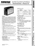
The Shure Model PS1A is an ac power supply that pro-
vides phantom power for one or two Shure SM81, SM82,
SM8S, or other condenser microphones. The PS1A can be
used with either balanced or unbalanced low-impedance
microphone inputs, and is designed to handle both
microphone- and line-level signals. It features extremely
low noise, hum and RF susceptibility. The PS1A will
operate over a wide range of ac voltages, and provides
short-circuit-proof operation.
The PS1A contains a power switch, power-on indicator,
two each male and female XLR connectors, and an internal
voltage selector switch for 240-volt, 50/60 Hz operation.
The PS1A is Listed by Underwriters Laboratories, Inc., and
is listed by Canadian Standards Association as Certified.
Features
e Phantom powers one or two Shure condenser
microphones or similar condenser microphones
e Use with balanced or unbalanced low-impedance
microphone inputs
e Low noise, hum and RF susceptibility
e Short-circuit-proof operation
e Operates with both microphone- and line-level
signals
* Usable over wide ac voltage ranges
e Three-pin XLR audio connectors
e Lightweight
e Rugged construction
e Listed by Underwriters Laboratories, Inc., and listed
by Canadian Standards Association as Certified
SPECIFICATIONS
Type
All-silicon-transistor power supply
Open Circuit Supply Voltage
21.5 + 1.5 Vdc, regulated (see Figure 1)
Shure Brothers Incorporated
222 Hartrey Avenue
Evanston IL 60202-3696 U.S.A.
Model PS1A User Guide
Supply Voltage Polarity
Positive (+) on three-socket Microphone connector
pins 2 and 3; negative ( — ) on pin 1 and case
Typical Supply Operating Conditions (each channel)
20 V at 1.5 mA (with Shure SM81 or SM85); 15 V at 8 mA
(with Shure SM82)
Power Supply Resistors
1.69 К = 1% (two per channel; see Figure 1)
Frequency Response
+0/ — 0.2 dB, 20-20,000 Hz (with SM81 or SM85 and
1k load)
Maximum Operating Level
Greater than +24 dBm
Short Circuit Supply Current
25 mA each channel (pins 2 and 3 to pin 1)
Hum and Noise (20 Hz-20 kHz, unweighted)
Common Mode: —90 dBV maximum
Differential Mode: —115 dBV maximum
Noise
300 Hz-20 kHz, unweighted
Common Mode: 100 dBV maximum
Differential Mode: —115 dBV maximum
A-weighted, measured with true rms voltmeter
Differential Mode: — 131 dBV maximum
Crosstalk
— 115 dB or less
Phasing
Corresponding pins of all connectors are in phase
Operating Voltage
90-132 Vac, 50/60 Hz or 180-264 Vac, 50/60 Hz (internal
switch-selectable); power consumption 3 watts maxi-
mum
Temperature Range
Operating: —7° to 57° C (20° to 135° F)
Storage: —29° to 71° C (—20° to 160° F)
Connectors
Professional audio (XLR): male (Output) and female
(Microphone)
Dimensions
72 mm H x 156 mm W x 150 mm D (2-27/32 in. x 6-5/32
in. x 5-29/32 in.)
Weight
1.25 kilograms (2 Ib 12 07)
Construction
Aluminum front panel with steel cover; finished in
gray enamel
Certifications
Listed by Underwriters Laboratories, Inc.; listed by
Canadian Standards Association as Certified
O 1996, Shure Brothers Incorporated
27A8087 (IF)
Printed in U.S.A.
MICROPHONE OUTPUT
ı 2 а
E - 7 |
- 1.869% -
+ 218 vDC _
"en | |
1.69K
SIMPLIFIED EQIVALENT CIRCUIT
(ONE CHANNEL)
FIGURE 1
OPERATION
Installation
WARNING
To reduce the risk of fire of electric shock, do
not expose this appliance to rain or extreme
moisture.
The PS1A can be installed anywhere along the micro-
phone line between the microphone and the mixer,
audio console, amplifier or tape recorder, and conven-
ient to an ac power source. Connect one or two SM81,
SM82, SM85 or other Shure condenser microphones to
the PS1A Microphone connectors. NOTE: When using
other manufacturer's condenser microphones with the
PS1A, verify that the voltage and resistance re-
quirements are compatible.
Connect a second cable from each PS1A Output con-
nector to a mixer input connector.
The design of the PS1A permits the simultaneous
operation of both a microphone-level and a line-level
condenser microphone.
The PS1A phantom powering system uses the balanc-
ed audio cable pair to carry the supply current to the
microphone. The cable shield is used as a ground
return. Use only high-quality microphone cables, as in-
termittent shorts between broken shield wires and the
balanced conductors will interrupt the current, causing
larae noise transients in the system. Avoid ground
loops that may occur due to connector shells or the
microphone case touching other metal objects. Incor-
porate generally accepted audio grounding practices.
Note that a PS1A can be used with either balanced or
unbalanced low-impedance microphone inputs.
Power Connections
Connect the ac power plug to a grounded 90 to 132
Vac, 50/60 Hz power source. Turn on the Power switch.
The LED lamp above the power switch will tight when
power is applied. If the PS1A is to be operated from a
180 to 264 Vac, 50/60 Hz power source, the modification
described in the next section must be performed.
SERVICE
WARNING
Voltages in this equipment are hazardous to
life. Refer servicing to qualified service person-
nel.
240V Operation
The PS1A is designed for operation from either a 90 to
132 Vac, 50/60 Hz or a 180 to 264 Vac, 50/60 Hz ac power
source. The operating voltage is selected by an internal
switch, and the unit is supplied with the switch set for
90 to 132 Vac operation.
For operation from a 180 to 264 Vac, 50/60 Hz power
source, follow these steps.
1. Unplug the ac line cord and remove the two self-
tapping screws securing the top cover.
2. Remove the top cover.
Locate the voltage selector switch and move it to
the 240V position.
4. Replace the line cord (if necessary) with one
designed for the new ac source. If the PS1A is to be
used outside the U.S. and Canada, local regulations
may require replacing the line cord with one having
wire insulation colors as follows:
“Live” or Earth or
“Hot” Neutral Ground
U.S., Canada Black White Green
Europe Brown Blue Green/Yellow
5. Replace the top cover and mark the rear panel to
reflect the new operating voltage.
REPLACEMENT PARTS LIST
REFERENCE SHURE PART OR
DESIGNATION DESCRIPTION COMERCIAL ALTERNATE"
C101-C104 Capacitor, Electrolytic, 100 uF, 50V Sprague 503D107F050PD
C105 Capacitor, Electrolytic, 470 pF, 50V Sprague 503D477F050QG
C106 Capacitor, Electrolytic, 220 uF, 50V Sprague 503D227F050QE
C107 Capacitor, Electrolytic, 4.7 uF, 50V Sprague 475M0O63AA3D
D101-D102, Diode, Silicon Rectifier, 100V, 1/2A Shure RKC21;** Motorola 1N4002
D105-D108
D104 Zener Diode, 22V, 5%, 250 mW Motorola 1N4115
J101-J102 Connector, Female XLR, Microphone | Switchcraft D3F
J103-J104 Connector, Male XLR, Output Switchcraft D3M
Q101 Transistor, Silicon, PNP Shure 86A353; Motorola MPS-U52
Q102 Transistor, Silicon, NPN Shure 86C349; Motorola 2N5088
R101-R104 Resistor, Metal Film, 1.69 k, 1/2W, 1% | TRW/IRC T0-60
R109 Resistor, Metal Oxide, 47, 1/2W RCA 830047
S1 Switch, Slide, DPDT, Voltage Selector | None
s2 Switch, Slide, DPDT, Power None
T1 Transformer, Power None
W1 Line Cord, 3-Conductor, 2.7 m (7 ft) Shure 95A8015
*Parts listed as “None” should be ordered from Shure Brothers Inc. listing product model number, reference
designation and part description.
**Supplied in multiples of four only.
PRINTED CIRCUIT BOARDS
38C0-PBMD
NOTES:
CIRCUIT DIAGRAM
TT TT о = WN TTT — = OUTPUT A
| E col [a | <-> 46 AN a:
/ 1 (E) 100X50 DIOG6 T
A EL NA002CQVD AY EL | e: I ¢
Т 00X50
' 835 838 | =
Ji | ES E38 | J3
|
| |
NUT B | GISD оют ‚а IN4002 ' OUTPUT B
e Ad CB. du cn 7e:
3 Y “10050 DIOS т
2Q E | GS» cios, N4002 COV _AE_YEL |
> "e
2 i : 2 $ : x ' :
J2 | & E § $ B = 8 | JA
us — Sx $
2 BE 38 |
. т 1
| |
| TT TT = 1
|
> > > {
L |
|
ax |
240V
о |
Г». —
EN © |
120V |
Wi —
120v/200V |
50/ 60 Hz
WHT
|. ALL CAPACITORS IN MFD AND SOV OR MORE
ALL ELECTROLYTIC CAPACITORS SHOWN
UNLESS
OTHERWISE SHOWN.
IN MFD X VOLTS
2 RESETORS TO BE 15% IM WATT UNLESS OTHERWISE SPECIFIED
3 xy MARKNG CHASSIS GROUND
4 © >» DENOTES D
VARY 215% VALUES
C VOLTAGE
MARKED WITH
Y MARKING - PC BOARD GROUND
MEASURED
ALL VOLTAGES
LINE =i20Vv, 60rz DC VOLTAGES MEASURED WITH 10 MEGOHM VTVM
JACKS J!, J2,J43 ANO JA UNTERMINATED VALUES ARE TYPICAL AND MAY
MAY VARY 15%
WITH AC
A5014-11-1