1
2/12/07
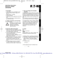
3.1 Polarity of the inputs
7:53 AM
Page 3
3.4 Multiplying factor
npn: sinking sensor
It can be set from
00.0001 up to 99.9999.
pnp: sourcing sensor
“0” is not accepted!
english
MN05401011E:MN05401011E
3.2 Switching on the 30 Hz filter (INP A, INP B)
The filter provides input
damping*
3.5 Dividing factor
30 Hz filter off (fmax)
It can be set from
00.0001 up to 99.9999.
30 Hz filter on
3.3 Input mode
“0” is not accepted!
Count input and count
direction input
INP A: Count input
INP B: Count direction input
Differential input
INP A: count input adding
INP B: count input
subtracting
Totalizing
INP A: count input adding
INP B: count input adding
Quadrature input
INP A: count input 0°
INP B: count input 90°
Quadrature input with pulse
doubling
INP A: count input 0°
INP B: count input 90°
Each pulse edge of INP A
will be counted
Quadrature input with pulse
quadrupling
INP A: count input 0°
INP B: count input 90°
Each pulse edge of INP A
and INP B will be counted.
* where bounce occurs, e.g. with contacts
MN05401011E
3.6 Decimal point
The decimal point defines
the way of displaying the
count values. It does not
affect counting.
0 no decimal place
0.0 one decimal place
0.00 two decimal places
0.000 three decimal places
3.7 SET/RESET mode
manual reset via the red
SET/RESET key and
electrical reset via the
SET/RESET input
no reset (red
SET/RESET key and
SET/RESET input locked)
only electrical reset via
the SET/RESET input
only manual reset via the
red SET/RESET key
3