1
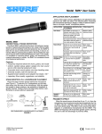
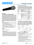
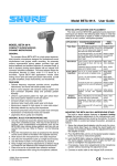
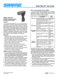
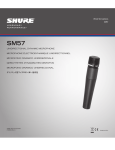
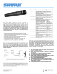
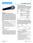
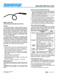
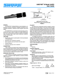
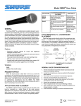
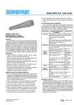
Shure Brothers Incorporated 222 Hartrey Avenue Evanston IL 60202-3696 U.S.A. Model SM57 User Guide APPLICATION AND PLACEMENT Some of the most common applications and placement techniques for the SM57 are listed in the following table. Remember that microphone technique is largely a matter of personal taste— there is no single “correct” microphone position. APPLICATION SUGGESTED MICROPHONE PLACEMENT TONE QUALITY Tom–Toms One SM57 on each tom, or between each pair of toms, 25 mm (1 in.) to 75 mm (3 in.) above the heads. Aim each mic at the top heads. Medium attack, balanced sound. On double head toms, remove the bottom head and place a mic inside aimed at the head. Medium attack, balanced sound. 25 mm (1 in.) to 75 mm (3 in.) above the rim of the top head of the drum. Aim the mic at the head. Most “snap” from drumstick impact If desired, place a second mic just below the rim of the bottom head. More “snare” sound. 25 mm (1 in.) from the speaker, on-axis with the speaker cone. Most attack, emphasized bass 150 mm (6 in.) to 300 mm (12 in.) away from speaker and on-axis with speaker cone. Medium attack, full, balanced sound .5 m (18 in.) to 1 m (3 ft) back from the speaker, on-axis with the speaker cone. Softer attack, thin, reduced bass sound. On-axis with the edge of the speaker cone. Thinner, reduced bass sound. Brass: .3 m (1 ft) to 1 m (3 ft) away, on-axis with bell of instrument. Bright, clear sound. Woodwinds: 25 mm (1 in.) to 150 mm (6 in.) away, on-axis with bell of instrument. Bright, clear sound. Bell of the instrument 90° offaxis from the front of the mic. Softer, mellow sound. 25 mm (1 in.) to 150 mm (6 in.) from the vocalist’s mouth. Rich, warm sound. MODEL SM57 UNIDIRECTIONAL DYNAMIC MICROPHONE The Shure SM57 unidirectional dynamic microphone is exceptional for musical instrument pickup or for vocals. With its bright, clean sound and carefully contoured presence rise, the SM57 is ideal for live sound reinforcement and recording. It has an extremely effective cardioid pickup pattern which isolates the main sound source while minimizing background noise. In the studio, it is excellent for recording drums, guitar, and woodwinds. For musical instruments or vocals, the SM57 is a consistent choice of professional performers. Snare Drum Guitar & Bass Amplifiers Features • Frequency response tailored for drums, guitars, and vocals • Uniform cardioid pickup pattern isolates the main sound source while reducing background noise • Pneumatic shock-mount system cuts down handling noise • Extremely durable under the heaviest use • Supplied break-resistant swivel adapter that rotates 180 ° • Legendary Shure quality, ruggedness, and reliability STAGE MONITOR & P.A. LOUDSPEAKER PLACEMENT Place the stage monitor directly behind the microphone (see Figure 1). Locate the P.A. loudspeakers so that they point away from the rear of the microphone. With the speakers located in these positions, the possibility of feedback is greatly reduced. Always check the stage setup before a performance to ensure optimum placement. 90° Vocals & Speech STAGE MONITOR P.A. LOUDSPEAKERS 0° 180° MICROPHONE 90° SOUND SOURCE RECOMMENDED LOUDSPEAKER PLACEMENT FIGURE 1 E1999, Shure Brothers Incorporated 27A2903 (SG) Brass & Woodwinds PROXIMITY EFFECT When the sound source is less than 6 mm (1/4 in.) from the microphone, the microphone boosts bass frequencies (by 6 to 10 dB at 100 Hz), creating a warmer and richer bass sound than when farther away. This effect, known as proximity effect, happens in unidirectional microphones like the SM57. The SM57 low-frequency roll-off provides greater control, allowing the user to take full advantage of proximity effect. Printed in U.S.A. GENERAL RULES FOR MICROPHONE USE Impedance Rated impedance is 150Ω (310Ω actual) for connection to microphone inputs rated low impedance. Polarity Positive pressure on diaphragm produces positive voltage on pin 2 with respect to pin 3 (see Figure 4). 1. Aim the microphone toward the desired sound source and away from unwanted sources. 2. Locate the microphone as close as practical to the desired sound source. 3. Work close to the microphone for extra bass response. 4. Use only one microphone per sound source. 5. Locate multiple microphones at least three times as far from other microphones as from the sound source. 6. Use as few microphones as practical. 7. Place microphones away from sound reflecting surfaces. 8. Add a windscreen when using the microphone outdoors, for closeup speech, or vocals. 9. Avoid excessive handling to minimize mechanical noise. SPECIFICATIONS Type Dynamic Frequency Response 40 to 15,000 Hz (see Figure 2) CARTRIDGE CODED TERMINAL GREEN BLUE 1 2 3 YELLOW RED BLACK TRANSFORMER INTERNAL CONNECTIONS FIGURE 4 Connector Three-pin professional audio connector (male XLR type) Case Dark gray, enamel-painted, die-cast steel with a polycarbonate grille and a stainless steel screen. 157 mm (6 3/16 in.) 23 mm (29/32in.) 32 mm (1 1/4 in.) DIMENSIONS FIGURE 4 Swivel Adapter Positive-action, break-resistant, adjustable through 180°, with standard 5/8 in.-27 thread Net Weight (without cable) 284 grams (10 oz) Certification Conforms to European Union directives, eligible to bear CE marking; meets European Union EMC Immunity Requirements (EN 50082–1: 1992). FURNISHED ACCESSORIES Swivel Adapter . . . . . . . . . . . . . . . . . . . . . . . . . . . . . . . A25D Storage Bag . . . . . . . . . . . . . . . . . . . . . . . . . . . . . . . . 26A13 TYPICAL FREQUENCY RESPONSE FIGURE 2 Polar Pattern Unidirectional (cardioid), rotationally symmetrical about microphone axis, uniform with frequency (see Figure 3) OPTIONAL ACCESSORIES Windscreen . . . . . . . . . . . . . . . . . . . . . . . . . . . . . . . . . . A2WS Desk Stand . . . . . . . . . . . . . . . . . . . . . . . . . . . . . S37A, S39A Isolation Mount . . . . . . . . . . . . . . . . . . . . . . . . . . . . . . . A55M Dual Mount . . . . . . . . . . . . . . . . . . . . . . . . . . . . A25M, A26M Cable (7.6 m [25 ft]) . . . . . . . . . . . . . . . . . . . . . C25E, C25F TYPICAL POLAR PATTERNS FIGURE 1 REPLACEMENT PARTS Cartridge . . . . . . . . . . . . . . . . . . . . . . . . . . . . . . . . . . . . . R57 Screen and Grille Assembly . . . . . . . . . . . . . . . . . . RK244G Sensitivity (at 1,000 Hz) Open Circuit Voltage: –54.5 dBV/Pa* (1.9 mV) *(1 Pa = 94 dB SPL) For additional service or parts information, please contact Shure’s Service department at 1-800-516-2525. Outside the United States, please contact your authorized Shure Service Center. 2 MODÈLE SM57 MICROPHONE DYNAMIQUE UNIDIRECTIONNEL Le Shure SM57 est un microphone dynamique unidirectionnel d’une qualité exceptionnelle, conçu pour la prise de son instrumentale et vocale. Une sonorité claire et nette alliée à une courbe de présence soigneusement étudiée font du SM57 le microphone idéal pour la sonorisation de scène et l’enregistrement. Il présente une configuration cardioïde extrêmement efficace, qui isole la source sonore principale tout en minimalisant le bruit de fond. En sudio, il est excellent pour l’enregistrement des percussions, guitares et instruments à anche. Le SM57 est le choix de prédilection des professionnels pour la sonorisation de la voix et des instruments. APPLICATION PLACEMENT SUGGÉRÉ SONORITÉ Toms Un SM57 sur chaque tom ou entre chaque paire de toms, de 2,5 à 7,5 cm au–dessus de la peau. Diriger chaque micro vers la peau de frappe. Attaque moyenne, son équilibré.. Sur les toms à double cerclage, la peau de dessous peut être retirée et le micro peut être placé à l’intérieur du fût, dirigé vers le haut. Attaque moyenne, son équilibré. 2,5 à 7,5 cm au dessus du cerclage de la peau de frappe. Diriger le micro vers la peau. Son le plus percutant. Un second micro peut être placé au–dessous du cerclage de la peau de dessous. Davantage de “timbre”. 2,5 cm du haut–parleur, au centre. Attaque maximum, basses accentuées 15 à 30 cm du haut–parleur, au centre. Attaque moyenne, son plein et équilibré. 50 cm à 1 m du haut parleur, au centre. Moins d’attaque son plus petit, basses réduites. Dirigé vers le bord de la membrane. Petit son, basses réduites. Cuivres : 30 cm à 1 m, dans l’axe du pavillon. Son clair et net. Anches : 2,5 à 15 cm, dans l’axe du pavillon. Son clair et net. À 90_ du pavillon de l’instrument. Son plus doux et feutré. 2,5 à 15 cm de la bouche du chanteur. Son chaud et plein. Caisse claire Avantages • Gamme de fréquences étudiée pour les percussions, la guitare et la voix • Configuration cardioïde uniforme isolant la source sonore principale tout en réduisant le bruit de fond • Système antichocs pneumatique réduisant les bruits de manipulation • Extrêmement durable dans les conditions les plus rigoureuses • Adaptateur incassable pivotant à 180_ • Qualité, fiabilité et robustesse légendaires de Shure Amplis de guitare et basse DISPOSITION DES RETOURS DE SCÈNE ET DES HAUTS–PARLEURS DE SONORISATION Placer le retour directement derrière le microphone (voir la figure 1). Disposer les hauts–parleurs de sonorisation de manière à ce qu’ils soient tournés à l’opposé de l’arrière du microphone pour réduire au maximum les risques de Larsen. Toujours vérifier la mise en place de la scène pour s’assurer que la disposition des microphones et haut–parleurs est optimale. Instruments à vent Voix 90° RETOUR HAUT–PARLEURS EFFET DE PROXIMITÉ Lorsque la source sonore se trouve à moins de 6 mm du microphone, les basses fréquences sont augmentées de 6 à 10 dB, à 100 Hz, produisant un son plus chaud et plus puissant. Ce phénomène, connu sous le nom d’effet de proximité est exclusif aux microphones dynamiques unidirectionnels tels que le SM57. L’atténuation de basses fréquences du SM57 assure un meilleur contrôle et permet à l’utilisateur de mieux tirer parti de l’effet de proximité. 0° 180° MICROPHONE 90° SOURCE SONORE PLACEMENT RECOMMANDÉ POUR LES HAUT–PARLEURS FIGURE 1 APPLICATIONS ET PLACEMENT Les applications les plus courantes du SM57 sont indiquées dans le tableau ci–dessous. Ne pas oublier que la technique de placement des micros est surtout une question de goût personnel et qu’il n’y a pas de position “correcte”. RÈGLES GÉNÉRALES D’UTILISATION DE MICROPHONES 1. Diriger le micro vers la source sonore, le plus à l’écart possible des bruits indésirables. 2. Placer le microphone aussi près que possible de la source sonore. 3. Plus la source sonore est proche du micro, plus les basses sont présentes. 4. N’utiliser qu’un microphone par source sonore. 5. La distance entre les microphones doit être d’au moins trois fois celle de chaque micro à sa source sonore respective. 3 6. 7. Utiliser le moins de microphones possible. Placer les microphones aussi loin que possible des surfaces réfléchissantes. 8. Utiliser un coupe–vent si les microphones sont utilisés à l’extérieur. 9. Éviter les manipulations inutiles pour minimiser le captage des bruits mécaniques. CARACTÉRISTIQUES Type Dynamique Courbe de réponse 40 à 15 000 Hz (voir la figure 2) Connecteur Connecteur professionnel 3 broches (mâle, type XLR) Corps Acier moulé émaillé gris foncé avec grille polycarbonate et coupe–vent en acier inoxydable Dimensions hors tout (voir la figure 5) 157 mm 23 mm 32 mm DIMENSIONS HORS TOUT FIGURE 5 Adaptateur de pied pivotant À emboîtement, incassable, réglable de 0 à 180_ avec filet standard de 5/8”–27 Poids net (sans câble) 284 grammes (10 oz.) Homologation Conforme aux directives de l’Union européenne, éligible pour recevoir le sceau de la CE; conforme aux normes de compatibilité électromagnétique de l’Union européenne (EN 50082–1: 1992). ACCESSOIRES FOURNIS Adaptateur de pied pivotant . . . . . . . . . . . . . . . . . . . . . . A25D Étui de rangement . . . . . . . . . . . . . . . . . . . . . . . . . . . . . . 26A13 ACCESSOIRES EN OPTION Coupe vent . . . . . . . . . . . . . . . . . . . . . . . . . . . . . . . . . . . . A2WS Support de table . . . . . . . . . . . . . . . . . . . . . . . . . . S37A, S39A Monture isolante A55M Double monture . . . . . . . . . . . . . . . . . . . . . . . . . . A25M, A26M Câble de 7,6 m (25 pi.) . . . . . . . . . . . . . . . . . . . . C25E, C25F PIÈCES DE RECHANGE Cartouche . . . . . . . . . . . . . . . . . . . . . . . . . . . . . . . . . . . . . . . R57 Ensemble grille/résonateur . . . . . . . . . . . . . . . . . . . . RK244G Pour des informations plus détaillées sur les réparations ou les pièces de rechange, contacter le service après–vente de Shure, au 1–800–516–2525. Hors des États–Unis, contacter le centre de réparations agréé de Shure. FRÉQUENCE HERTZIENNE COURBE DE RÉPONSE TYPIQUE FIGURE 2 Courbe de directivité Unidirectionnelle (cardioïde), rotativement symétrique autour de l’axe du microphone, constante avec la féquence (voir la figure 3) COURBES DE DIRECTIVITÉ TYPIQUES FIGURE 3 Niveau de sortie (à 1000 Hz) Tension en circuit ouvert : –54,5 dBV/Pa (1,9 mV) Impédance L’impédance nominale est de 150 W (310 W réelle) pour connexion aux entrées de micros basse impédance Polarité Une pression positive sur le diaphragme produit une tension positive sur la broche 2 par rapport à la broche 3 CARTOUCHE CODÉE VERT BLEU 1 2 3 JAUNE ROUGE TRANSFORMATEUR NOIR CONNEXIONS INTERNES FIGURE 4 4 MODELL SM57 UNIDIREKTIONALES DYNAMISCHES MIKROPHON Das unidirektionale dynamische Mikrophon Shure SM57 eignet sich hervorragend für die Aufnahme von Musikinstrumenten oder Gesang. Mit seinem hellen, reinen Klang und sorgfältig konturierten Präsenzanstieg ist das SM57 ideal für Live–Tonverstärkung und –aufnahmen. Es weist eine äußerst wirksame Nieren–Aufnahmecharakteristik auf, die die Haupttonquelle isoliert und zugleich Hintergrundgeräusche auf ein Minimum reduziert. Im Studio läßt es sich ausgezeichnet für Aufnahmen von Trommeln, Gitarren und Holzblasinstrumenten einsetzen. Sei es für Musikinstrumente oder Gesang – Profis entscheiden sich immer wieder für das SM57. ANWENDUNG EMPFOHLENE MIKROPHONAUFSTELLUNG TONQUALITÄT Tomtoms Ein SM57 bei jedem Tom oder zwischen jedem Tomtom– Paar, 2,5 bis 7,5 cm über den Trommelfellen. Jedes Mikrophon auf die oberen Felle richten. Mittelstarker Toneinsatz, ausgeglichener Klang. Bei Doppelfell–Tomtoms das untere Fell entfernen und im Inneren ein Mikrophon anbringen, das auf das obere Fell gerichtet ist. Mittelstarker Toneinsatz, ausgeglichener Klang. 2,5 bis 7,5 cm über dem Rand des oberen Trommelfells. Das Mikrophon auf das Fell richten. Stärkster “knalliger” vom Aufschlag des Trommelstocks. Auf Wunsch ein zweites Mikrophon etwas unterhalb des unteren Fellrands anbringen. Gezielte Abnahme des Snare Teppichs. 2,5 cm Abstand vom Lautsprecher, axial zum Lautsprechertrichter. Stärkster Toneinsatz, hervorgehobener Baß. 15 bis 30 cm Abstand vom Lautsprecher und axial zum Lautsprechertrichter. Mittelstarker Toneinsatz, voller, ausgeglichener Klang. 50 cm bis 1 m Abstand vom Lautsprecher, axial zum Lautsprechertrichter. Weicherer Toneinsatz, dünner, reduzierter Baßklang. Axial zur Kante des Lautsprechertrichters. Dünnerer, reduzierter Baßklang. Blechblasinstrumente: 30 cm bis 1 m Abstand, axial zum Instrumententrichter. Heller, klarer Klang. Holzblasinstrumente: 2,5 bis 15 cm Abstand, axial zum Instrumententrichter. Heller, klarer Klang. Instrumententrichter 90_ senkrecht zur Vorderseite des Mikrophons. Weicherer, lieblicher Klang. 2,5 bis 15 cm Abstand vom Mund des Sängers. Voller, warmer Klang. Snare drum Merkmale • Frequenzverhalten auf Trommeln, Gitarren und Gesang zugeschnitten • Gleichförmige Nieren–Aufnahmecharakteristik isoliert die Haupttonquelle und reduziert zugleich Hintergrundgeräusche • Pneumatisches Dämpfer–System verringert Handhabungsgeräusche • Äußerst dauerhaft auch unter extremen Einsatzbedingungen • Mit einem bruchfesten, um 180_ drehbaren Schwenkadapter ausgestattet • Bewährte Shure Qualität, Robustheit und Zuverlässigkeit AUFSTELLUNG DER BÜHNENLAUTSPRECHER UND LAUTSPRECHER FÜR BESCHALLUNGSANLAGE Den Bühnenlautsprecher direkt hinter dem Mikrophon aufstellen (siehe Abbildung 1). Die Lautsprecher der Beschallungsanlage so plazieren, daß sie von der Rückseite des Mikrophons wegzeigen. Wenn sich die Lautsprecher an diesen Stellen befinden, wird das Risiko von Rückkopplungen stark reduziert. Vor einem Auftritt stets die Bühnenausstattung überprüfen, um die optimale Aufstellung sicherzustellen. Gitarren– und Baßverstärker Blech– und Holzblasinstrumente 90° BÜHNENLAUTSPRECHER LAUTSPRECHER DER BESCHALLUNGSANLAGE Sänger 0° 180° MIKROPHON NAHBESPRECHINGSEFFEKT Wenn die Tonquelle weniger als 6 mm vom Mikrophon entfernt ist, verstärkt das Mikrophon Baßfrequenzen (um 6 bis 10 dB bei 100 Hz), wodurch ein wärmerer und reicherer Baßklang als bei größeren Entfernungen erzeugt wird. Dieser Effekt, der als Nahbesprechingseffekt bezeichnet wird, tritt nur bei unidirektionalen dynamischen Mikrophonen wie dem SM57 auf. Das allmähliche Dämpfungsverhalten des SM57 bei niedrigen Frequenzen bietet eine bessere Regelung und ermöglicht dem Benutzer, den Nahbesprechingseffekt voll auszunutzen. ALLGEMEINE REGELN FÜR DEN MIKROPHONGEBRAUCH 1. Das Mikrophon auf die gewünschte Tonquelle und weg von unerwünschten Quellen richten. 2. Das Mikrophon so nahe wie möglich an die gewünschte Tonquelle heranbringen. 3. Abstand verringern, wenn zusätzliche Baßanhebung gewünscht wird. TONQUELLE 90° EMPFOHLENE LAUTSPRECHERAUFSTELLUNG ABBILDUNG 1 ANWENDUNG UND AUFSTELLUNG Einige der gebräuchlichsten Anwendungen und Aufstellungsverfahren für das SM57 sind in der nachfolgenden Tabelle aufgeführt. Beachten Sie bitte, daß der Mikrophoneinsatz weitgehend eine “Geschmackssache” ist – von “richtigen” oder “falschen” Mikrophonpositionen kann hier also nicht die Rede sein. 5 4. 5. Je Tonquelle nur ein Mikrophon verwenden. Die Mikrophone mindestens dreimal so weit von einander entfernt aufstellen wie von der Tonquelle. 6. So wenig Mikrophone wie möglich verwenden. 7. Mikrophone weit entfernt von Akustikflächen anbringen. 8. Einen Windschutzfilter anbringen, wenn das Mikrophon im Freien verwendet wird; das gilt sowohl für Sprach– als auch für Gesangsaufnahmen. 9. Mikrophone so wenig wie möglich anfassen, um mechanische Geräusche zu vermeiden. SPEZIFIKATIONEN Polarität Positiver Druck auf die Membran erzeugt positive Spannung an Stift 2 gegenüber Stift 3 (Abbildung 4). Typ Stecker Dreipoliger Profi–Tonstecker (XLR–Steckertyp) Gehäuse Dunkelgraues einbrennlackiertes Druckgußmetall mit Polycarbonat–Grill und Schirm aus rostfreiem Stahl KAPSEL GEKENNZEICHNET GRÜN BLAU 1 2 3 GELB ROT KRAFTTRANSFORMATOR SCHWARZ INTERNE SCHALTUNGEN ABBILDUNG 4 Dynamisch Frequenzgang 40 bis 15.000 Hz (siehe Abbildung 2) Gesamtabmessungen 157 mm 23 mm 32 mm GESAMTABMESSUNGEN ABBILDUNG 5 Schwenkadapter Formschlüssig, bruchfest, bis 180_ verstellbar, mit 5/8 Inch–27 Standardgewinde FREQUENZ IN Hz TYPISCHES FREQUENZGANG ABBILDUNG 2 Nettogewicht (ohne Kabel) 284 Gramm (10 Unzen) Zulassungen Entsprechend den EU–Richtlinien mit Berechtigung für das CE–Label; erfüllt die Sanforderungen der Europäischen Union hinsichtlich elektromagnetischer Störfelder (EN 50082–1: 1992). MITGELIEFERTES ZUBEHÖR Schwenkadapter . . . . . . . . . . . . . . . . . . . . . . . . . . . . . . . A25D Tasche . . . . . . . . . . . . . . . . . . . . . . . . . . . . . . . . . . . . . . . . 26A13 SONDERZUBEHÖR Windschutzfilter . . . . . . . . . . . . . . . . . . . . . . . . . . . . . . . . A2WS Tischstativ . . . . . . . . . . . . . . . . . . . . . . . . . . . . . . . . S37A, S39A Isolierbefestigung . . . . . . . . . . . . . . . . . . . . . . . . . . . . . . A55M Doppelbefestigung . . . . . . . . . . . . . . . . . . . . . . . A25M, A26M Kabel (7,6 m [25 Fuß]) . . . . . . . . . . . . . . . . . . . . C25E, C25F ERSATZTEILE Kapsel . . . . . . . . . . . . . . . . . . . . . . . . . . . . . . . . . . . . . . . . . . R57 Grillresonator–Baugruppe . . . . . . . . . . . . . . . . . . . . . RK244G Weitere Informationen über Service oder Ersatzteile erhalten Sie von der Shure Kundendienstabteilung unter der Telefonnummer 1–800–516–2525. Außerhalb der Vereinigten Staaten wenden Sie sich bitte an Ihr Shure Vertragskundendienstzentrum. Polarcharakteristik Unidirektionale (Nieren–) Charakteristik, rotationssymmetrisch um Mikrophonachse, gleichförmig mit Frequenz (siehe Abbildung 3) TYPISCHE POLARCHARAKTERISTIK ABBILDUNG 3 Ausgangspegel (bei 1000 Hz) Leerlaufspannung: –54,5 dBV/Pa (1,9 mV) Impedanz Die Nennimpedanz für den Anschluß an niederohmige Mikrophoneingänge beträgt 150 W (Ist–Wert 310 W). 6 MODELO SM57 MICROFONO DINAMICO UNIDIRECCIONAL El Shure SM57 es un micrófono dinámico unidireccional de rendimiento excepcional para captar instrumentos o voces. Con su sonido claro y brillante y su aumento de frecuencias de presencia cuidadosamente ajustado, el SM57 es ideal para refuerzo de sonido en directo y para grabaciones. Cuenta con una dispersión polar cardioide altamente eficaz que aisla la fuente principal de sonido a la vez que reduce al mínimo los ruidos de fondo. En el estudio, es excelente para grabar tambores, guitarras e instrumentos de viento. Para la captación de instrumentos musicales y voces, el SM57 es la elección lógica de los profesionales. USO COLOCACION SUGERIDA DEL MICROFONO CALIDAD DEL TONO Tambores tom–tom Un SM57 en cada tom–tom, o en cada par de tom–tom, de 2,5 a 7,5 cm sobre sus membranas. Apunte cada micrófono hacia las membranas superiores. Respuesta media, sonido equilibrado. En los tom–tom de membrana Respuesta medoble, se puede quitar la dia, sonido equimembrana inferior e insertar librado. el micrófono en su interior apuntando hacia la membrana superior. Tambor repicador Características • Respuesta a frecuencias diseñada para captar tambores, guitarras y voces • La dispersión polar cardioide uniforme aisla la fuente sonora principal a la vez que reduce los ruidos de fondo • El sistema de montaje neumático resistente a choques reduce los ruidos causados por el manejo • Extremadamente duradero aún en las condiciones más adversas • Incluye un adaptador giratorio resistente a las roturas que gira 180_ • La legendaria calidad, robustez y fiabilidad de Shure COLOCACION DE ALTAVOCES DE PA Y MONITOR DE ESCENARIO Coloque el monitor de escenario directamente detrás del micrófono (vea la Figura 1). Coloque los altoparlantes de P.A. de manera que el sonido que emiten se aleje de la parte trasera del micrófono. Cuando los altavoces se colocan en estas posiciones, la posibilidad de realimentación se reduce significativamente. Siempre compruebe la disposición del escenario antes de una actuación para verificar que la colocación es la óptima. MONITOR DE ESCENARIO ALTAVOCES DE P.A. Amplificadores de guitarra y bajor Instrumentos de viento 90° 0° 180° MICROFONO 90° Cantantes y oradores FUENTE SONORA De 2,5 a 7,5 cm sobre el aro de la membrana superior del tambor. Apunte el micrófono hacia la membrana superior. Mayor captación del chasquido del impacto de los palillos. Si se desea, se puede colocar un segundo micrófono justo debajo del aro de la membrana inferior. Más sonido de “repique”. A 2,5 cm del altavoz, sobre el eje del cono del parlante. Respuesta más fuerte, bajas frecuencias enfatizadas. De 15 a 30 cm del altavoz y sobre el eje del cono del altavoz. Respuesta media, sonido equilibrado y pleno. De 50 cm a 1 m del altavoz, sobre el eje del cono del altavoz. Respuesta más suave, sonido agudo con frecuencias bajas reducidas. Sobre el eje del borde del cono del altavoz. Sonido más agudo con frecuencias bajas reducidas. De metal: De 30 cm a 1 m de distancia, sobre el eje de la bocina del instrumento. Sonido brillante y claro. De madera: De 2,5 a 15 cm de distancia, sobre el eje de la bocina del instrumento. Sonido brillante y claro. Bocana del instrumento a 90_ del eje de captación del micrófono. Sonido más suave y melodioso De 2,5 a 15 cm de la boca de la persona. Sonido rico y cálido. EFECTO DE PROXIMIDAD Cuando la fuente sonora se encuentra a menos de 6 mm del micrófono, éste introduce un aumento progresivo en las frecuencias bajas (de 6 a 10 dB a 100 Hz) que crea un sonido de frecuencias bajas más cálido y fuerte que cuando la fuente está más alejada. Este efecto, conocido como el efecto de proximidad, se produce únicamente en micrófonos dinámicos unidireccionales tales como el SM57. La atenuación progresiva de frecuencias bajas que incorpora el SM57 ofrece mayor control sobre el sonido y ayuda al usuario a aprovechar el efecto de proximidad. REGLAS GENERALES DE USO DE MICROFONOS 1. Apunte el micrófono hacia la fuente sonora deseada y alejado de las fuentes no deseadas. COLOCACION RECOMENDADA DE LOS ALTAVOCES FIGURA 1 USOS Y COLOCACION Algunas de las técnicas más comunes de uso y colocación del SM57 se indican en la tabla siguiente. Recuerde que la técnica de uso de los micrófonos es en gran parte cuestión de gusto personal—no existe una posición de micrófono que sea la “correcta”. 7 Coloque el micrófono lo más cerca posible a la fuente sonora deseada. 3. Acérquese al micrófono para obtener mayor respuesta de frecuencias bajas. 4. Utilice sólo un micrófono para captar una fuente sonora. 5. La distancia entre un micrófono y otro deberá ser al menos tres veces la distancia de cada fuente a su micrófono. 6. Utilice el menor número de micrófonos que resulte práctico. 7. Aleje los micrófonos lo más posible de las superficies reflectoras. 8. Instale un paravientos si se usa el micrófono a la intemperie, o al captar una voz a muy poca distancia. 9. Evite el manejo excesivo para reducir la captación de ruidos mecánicos. ESPECIFICACIONES Polaridad Una presión positiva en el diafragma del micrófono produce un voltaje positivo en la patilla 2 con respecto a la patilla 3 (Figura 4). Tipo Dinámico Caja Acero fundido a troquel esmaltado en color gris oscuro con una rejilla de policarbonato y una malla de acero inoxidable 2. CAPSULA CODIF VERDE AZUL 1 2 3 AMARILLO ROJO TRANFORMADOR NEGRO CONEXIONES INTERNAS FIGURA 4 Conector Conector de audio de tres patillas profesional (tipo XLR macho) Respuesta a frecuencias 40 a 15.000 Hz (vea la Figura 2) Dimensiones totales 157 mm (6 3/16 in.) 23 mm (29/32in.) 32 mm (1 1/4 in.) DIMENSIONES TOTALES FIGURA 5 Adaptador giratorio De acción positiva, resistente a roturas, 180_ de ajuste con rosca estándar de 5/8 pulg–27 FRECUENCIA EN Hz RESPUESTA A FRECUENCIAS TIPICA FIGURA 2 Peso neto (sin cable) 284 g (10 oz) Certificaiones Cumple con las directivas de la Unión Europea, elegible para la marca CE; Cumple con los requisitos de inmunidad y normas de propiedades electromagnéticas (EMC) de la Unión Europea (EN 50082–1: 1992). ACCESORIOS SUMINISTRADOS Adaptador giratorio . . . . . . . . . . . . . . . . . . . . . . . . . . . . . A25D Bolsa de almacenamiento . . . . . . . . . . . . . . . . . . . . . . . 26A13 ACCESORIOS OPCIONALES Paravientos . . . . . . . . . . . . . . . . . . . . . . . . . . . . . . . . . . . A2WS Pie de sobremesa . . . . . . . . . . . . . . . . . . . . . . . . . S37A, S39A Montaje con aislamiento . . . . . . . . . . . . . . . . . . . . . . . . A55M Montaje doble . . . . . . . . . . . . . . . . . . . . . . . . . . . A25M, A26M Cable (7,6 m [25 pies]) . . . . . . . . . . . . . . . . . . . . C25E, C25F REPUESTOS Cartucho . . . . . . . . . . . . . . . . . . . . . . . . . . . . . . . . . . . . . . . . R57 Conjunto de rejilla de resonancia . . . . . . . . . . . . . . . RK244G Para información adicional acerca del servicio o repuestos, llame al Departamento de servicio Shure al teléfono 1–800–516–2525. Fuera de los EE.UU., llame al servicentro autorizado de productos Shure. Dispersión polar Unidireccional (cardioide), simétrico respecto al eje del micrófono, uniforme respecto a la frecuencia (vea la Figura 3) DISPERSIONES POLARES TIPICAS FIGURA 3 Nivel de salida (a 1000 Hz) Voltaje de circuito abierto: –54,5 dBV/Pa (1,9 mV) Impedancia La impedancia nominal es de 150 Ω (real: 310 Ω) para conexión a entradas de micrófono de baja impedancia. 8 MODELLO SM57 MICROFONO DINAMICO UNIDIREZIONALE Il modello SM57 della Shure è un microfono dinamico unidirezionale che offre prestazioni eccezionali per la riproduzione di suoni vocali o strumentali. Grazie al suo suono chiaro e limpido e all’accurato profilo della risposta in frequenza con cui viene ottenuto l’effetto di prossimità, questo modello è ideale per la registrazione e l’amplificazione di suoni dal vivo. Presenta un diagramma di polare a cardioide estremamente efficace, che isola la sorgente sonora principale e nello stesso tempo riduce al minimo il rumore di fondo. In studio, è eccellente per la registrazione dei suoni di batterie, chitarre e legni. Sia per applicazioni vocali che strumentali, il microfono SM57 costituisce una scelta che garantisce prestazioni costanti ai professionisti della musica. APPLICAZIONE COLLOCAZIONE DEL MICROFONO SUGGERITA QUALITÀ DEI TONI Toms Un SM57 per ciascuna tom oppure tra ciascuna coppia di toms, da 2,5 a 7,5 cm sopra il bordo. Rivolgere ciascun microfono verso il bordo superiore. Attacco medio, suono bilanciato. Su casse a dotate di due pelli, rimuovere quella inferiore inferiore e collocare il microfono all’interno rivolto verso la pelle superiore. Attacco medio, suono bilanciato. Da 2,5 a 7,5 cm sopra il bordo superiore. Rivolgere il microfono verso il bordo. Principalmente schioccante, a causa dell’impatto delle bacchette. Se lo si desidera, collocare un secondo microfono appena sotto il bordo inferiore. Suono più riverberante. 2,5 cm di distanza dall’altoparlante, lungo l’asse del cono dell’altoparlante stesso. Brillante attacco, enfasi sui toni bassi. Da 15 a 30 cm di distanza dall’altoparlante e lungo l’asse del cono dell’altoparlante stesso. Attacco medio, suono pieno e bilanciato. Da 50 cm a 1 m di distanza dall’altoparlante e lungo l’asse del cono dell’altoparlante stesso. Attacco più morbido, toni bassi ridotti e sfumanti. Lungo l’orlo del cono dell’altoparlante. Toni bassi ridotti e più affievoliti. Ottoni: da 30 cm a 1 m di distanza, lungo l’asse della campana dello strumento. Suono chiaro e limpido. Legni: da 2,5 a 15 cm di distanza, lungo l’asse della campana dello strumento. Suono chiaro e limpido. Campana dello strumento a 90_ rispetto all’asse dalla parte anteriore del microfono. Suono dolce e più morbido. Da 2,5 a 15 cm di distanza dalle a bocca del cantante o dell’oratore. Suono caldo e ricco. Rullante Caratteristiche • Risposta in frequenza ottimizzata per batterie, chitarre ed applicazioni vocali. • Diagramma di polare a cardioide uniforme, che isola la sorgente sonora principale e nello stesso tempo riduce al minimo il rumore di fondo. • Sistema pneumatico di supporto antivibrazione che riduce il rumore derivante dal maneggiamento. • Estremamente robusto, anche nell’uso più gravoso. • Include un adattatore a snodo, resistente a rotore accidentali da rottura, orientabile a 180_. • La leggendaria qualità, robustezza e affidabilità Shure. COLLOCAZIONE DEGLI ALTOPARLANTI PER IL PUBBLICO E DI CONTROLLO DEL MONITOR DI PALCO Collocare l’altoparlante di controllo del palcoscenico direttamente dietro il microfono (vedi Figura 1). Collocare gli altoparlanti per il pubblico in modo che siano rivolti in direzione opposta rispetto alla parte posteriore del microfono. Con tale disposizione degli altoparlanti si riduce enormemente la possibilità di effetti di feedback. Prima della rappresentazione, controllare sempre l’allestimento del palcoscenico per verificare la collocazione ottimale del microfono e degli altoparlanti. Amplificatori per chitarre e bassi Ottoni e legni Voce 90° ALTOPARLANTE DI CONTROLLO MONITOR PER IL PUBBLICO EFFETTO DI PROSSIMITÀ Quando la sorgente sonora si trova a meno di 6 mm di distanza dal microfono, la risposta alle basse frequenze aumenta progressivamente (da 6 a 10 dB a 100 Hz), generando dei toni bassi più ricchi e caldi rispetto a distanze maggiori della sorgente stessa dal microfono. Questo fenomeno, noto come effetto di prossimità, si verifica solo in microfoni dinamici unidirezionali come il modello SM57. L’attenuazione alle basse frequenze del modello SM57 fornisce un controllo maggiore e consente a chi usa il microfono di sfruttare pienamente l’effetto di prossimità. REGOLE GENERALI PER L’USO DEL MICROFONO 1. Rivolgere il microfono verso la sorgente sonora desiderata e lontano da sorgenti indesiderate. 2. Collocare il microfono quanto più vicino possibile alla sorgente sonora desiderata. 3. Per ottenere una maggiore risposta ai toni bassi, tenere il microfono vicino alla bocca. 4. Usare solo un microfono per ciascuna sorgente sonora. 0° 180° MICROFONO 90° SORGENTE SONORA COLLOCAZIONE SUGGERITA DEGLI ALTOPARLANTI FIGURA 1 APPLICAZIONI E COLLOCAZIONE La tabella che segue riporta le più comuni applicazioni e le tecniche di collocazione del modello SM57. Rammentare sempre che le tecniche microfoniche dipendono largamente dalle preferenze personali e che non esiste una unica posizione “giusta” del microfono. 9 CARTUCCIA CODICE 5. Mantenere la distanza tra più microfoni ad un valore uguale ad almeno tre volte la distanza tra ciascun microfono e la sorgente sonora. 6. Usare il numero minimo di microfoni consentito dall’applicazione. 7. Collocare i microfoni quanto più lontano possibile da superfici fonoriflettenti. 8. Quando si usa il microfono all’aperto, per cantanti od oratori a distanza ravvicinata, utilizzare uno schermo antivento. 9. Evitare movimenti eccessivi del microfono, per ridurre il rumore di maneggiamento. DATI TECNICI VERDE BLU 1 2 3 GIALLO ROSSO TRANSFORMATORE NERO COLLEGIAMENTI INTERNI FIGURA 4 Connettore Connettore audio professionale a tre piedini (tipo XLR maschio). Tipo Dinamico Contenitore Corpo in metallo pressofuso, grigio scuro, smaltato con griglia in policarbonato e schermo in acciaio inossidabile. Dimensioni totali Risposta in frequenza Da 40 a 15.000 Hz (vedi Figura 2) 157 mm 23 mm 32 mm DIMENSIONI TOTALI FIGURA 5 Adattatore regolabile Senza slittamento, resistente a sollecitazioni da rottura, regolabile in un angolo di 180_, con filettatura standard 5/8” – 27. FREQUENZA, Hz RISPOSTA IN FREQUENZA TIPICA FIGURA 2 Peso netto (senza cavo) 284 g (10 once) Omologazioni Conforme alle direttive della Comunità Europea, contrassegnabile con il marchio CE; questo prodotto è conforme ai requisiti sull’immunità relativi alla CEM (compatibilità elettromagnetica) specificati dalla Comunità Europea [NSE (Norme europee) 50082–1: 1992]. ACCESSORI IN DOTAZIONE Addattatore regolabile . . . . . . . . . . . . . . . . . . . . . . . . . . A25D Borsa . . . . . . . . . . . . . . . . . . . . . . . . . . . . . . . . . . . . . . . . . 26A13 OPTIONAL Schermo antivento . . . . . . . . . . . . . . . . . . . . . . . . . . . . . A2WS Base da tavolo . . . . . . . . . . . . . . . . . . . . . . . . . . . . S37A, S39A Adattatore antibrazioni . . . . . . . . . . . . . . . . . . . . . . . . . . A55M Adattatore doppio . . . . . . . . . . . . . . . . . . . . . . . . A25M, A26M Cavo (7,6 m [25 piedi]) . . . . . . . . . . . . . . . . . . . . C25E, C25F RICAMBI Capsula . . . . . . . . . . . . . . . . . . . . . . . . . . . . . . . . . . . . . . . . . R57 Gruppo griglia risonatore . . . . . . . . . . . . . . . . . . . . . . RK244G Per ulteriori informazioni sui ricambi o per assistenza, chiamare l’assistenza clienti della Shure al numero verde 1–880–516–2525 (solo negli Stati Uniti). Fuori dagli Stati Uniti, rivolgersi al rivenditore o ad un centro di assistenza autorizzato. Diagramma polare Unidirezionale (cardioide) con simmetria rotazionale rispetto all’asse del microfono, uniforme con la frequenza (vedi Figura 3). DIAGRAMMI POLARI TIPICI FIGURA 3 Livelli di uscita (a 1.000 Hz) Tensione a circuito aperto: –54,5 dBV/Pa (1,9 mV) Impedenza Valore nominale: 150 W (310 W effettivi) per il collegamento a ingressi microfonici con bassi valori nominali di impedenza. Polarità Una pressione positiva sul diaframma produce una tensione positiva al piedino 2 rispetto al piedino 3 (Figura 4) 10 11 A25D The Sound of Professionals...Worldwide Shure Brothers Incorporated 222 Hartrey Avenue, Evanston IL 60202-3696 Phone: In Europe, Phone: Internationally, Phone: 12 847 866-2200 FAX: 847 866-2279 49-7131-72140 FAX: 49-7131-721414 847 866-2200 FAX: 847 866-2585