1
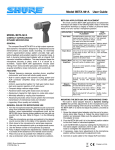
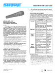
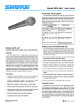
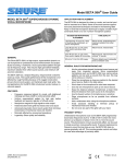
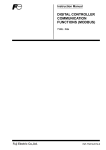
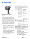
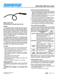
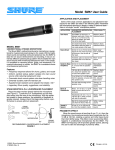
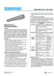
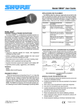
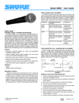
Model Beta 56 User Guide BETA 56 APPLICATIONS AND PLACEMENT The most common BETA 56 applications and placement techniques are listed in the following table. Keep in mind that microphone technique is largely a matter of personal taste; there is no one “correct” microphone position. MODEL BETA 56 APPLICATION SUGGESTED MICROPHONE PLACEMENT TONE QUALITY Tom–Toms One BETA 56 on each tom, or between each pair of toms, 2.5 to 7.5 cm (1 to 3 in.) above drum heads. Aim each mic at top drum heads. On double head toms, you can also remove bottom head and place a mic inside pointing up toward top drum head. Medium attack; full, balanced sound. 2.5 to 7.5 cm (1 to 3 in.) above rim of top head of drum. Aim mic at drum head. If desired, place a second mic just below rim of bottom head. Most “snap” from drumstick. Guitar & Bass 2.5 cm (1 in.) from speaker, on– Amplifiers axis with center of speaker cone. 15 to 30 cm (6 to 12 in.) away from speaker and on–axis with speaker cone. Sharp attack; emphasized bass. Sharp attack; higher frequency sound. Medium attack; full, balanced sound. 60 to 90 cm (2 to 3 ft .) back from speaker, on–axis with speaker cone. Softer attack; reduced bass. Brass: 30 to 90 cm (1 to 3 ft.) away, on–axis with bell of instrument. Woodwinds: 2.5 to 15 cm (1 to 6 in.) away, on–axis with bell of instrument. Bell of instrument 90° off–axis from front of mic. Bright, clear sound. Bright, clear sound. COMPACT SUPERCARDIOID DYNAMIC MICROPHONE GENERAL The compact Shure BETA 56 is a high output supercardioid dynamic microphone designed for professional sound reinforcement and project studio recording. Its extremely uniform supercardioid pickup pattern provides high gain before feedback and excellent rejection of unwanted noise. A built–in dynamic locking stand adapter with an integral XLR connector simplifies installation. The stand adapter keeps the microphone securely in place, even if it is struck by a drumstick. Typical BETA 56 applications include close miking of tom–toms and other percussion instruments, as well as guitar amplifiers, brass instruments, and woodwinds. FEATURES • Tailored frequency response provides drums, amplified instruments, and horns with studio quality sound • Built–in stand adapter with dynamic locking system and XLR connector simplifies setup and provides greater flexibility • Uniform supercardioid pattern for high gain before feedback and superior rejection of off–axis sound • Compact design reduces stage clutter • Hardened steel mesh grille resists wear and abuse • Neodymium magnet for high signal–to–noise ratio output • Minimally affected by varying load impedance • Advanced pneumatic shock mount system that minimizes transmission of mechanical noise and vibration • Legendary Shure quality and reliability GENERAL RULES FOR MICROPHONE USE 1. Aim the microphone toward the desired sound source and away from unwanted sources. This may not be obvious or intuitive, since supercardioid microphones such as the BETA 56 have narrow pickup patterns and can pick up sounds from the rear. Refer to Figure 1 on the following page. 2. Place the microphone as close as practical to the desired sound source (refer to the table in the opposite column). 3. Work close to the microphone for extra bass response. 4. Use only one microphone to pick up a single sound source. 5. Use the fewest number of microphones as practical. 6. Keep multiple microphones separated by a distance equal to at least 3X the distance to the nearest sound source. 7. Place mics as far as possible from reflective surfaces. 8. Use a windscreen when using the microphone outdoors. 2001, Shure Incorporated 27C2798 (BA) Snare Drum 2.5 cm (1 in.) from speaker, at edge of speaker cone. Brass & Woodwinds Medium attack; full, balanced sound. More “snare” sound. Softer, mellow sound. MOUNTING THE BETA 56 ON A MICROPHONE STAND The built–in stand adapter features a dynamic locking system that permits adjustments to the microphone’s position, but resists slipping when struck by drumsticks. To mount the BETA 56 on a stand and adjust its position, proceed as follows: 1. Screw the integral stand adapter onto the end of a microphone stand (see Figure 4). Adjust the stand height and position as necessary. Make sure the adjustment knob on the adapter is loose. 2. Pivot the BETA 56 until it is in the desired position relative to the drum head or instrument speaker. 3. Lock the BETA 56 in place by rotating the thumbscrew on the stand adapter clockwise until it is tight. Do NOT use tools to overtighten the adjustment knob. 4. If necessary, make minor adjustments to the microphone position without loosening the adjustment knob. 5. Connect an audio cable to the integral XLR connector. Printed in Mexico STAGE MONITOR AND P.A. LOUDSPEAKER PLACEMENT For maximum rejection of unwanted sound, place the stage monitor(s) or P.A. system loudspeakers at a 60° angle from the rear of the Beta 56, not directly behind it (see Figure 1). Always check out the stage setup before a performance to ensure optimum placement of microphone and monitors. 180° MONITOR LOUDSPEAKER(S) Output Level (at 1,000 Hz) Open Circuit Voltage –51 dBV/Pa (2.8 mV) (1 Pa = 94 dB SPL) Impedance Rated impedance is 150 W (290 W actual) for connection to microphone inputs rated low Z Polarity Positive pressure on diaphragm produces positive voltage on pin 2 with respect to pin 3 P.A. SYSTEM LOUDSPEAKER 120° Connector Three–pin professional audio connector (male XLR type) 120° 90° 90° Case Silver blue enamel–painted die cast metal with hardened, matte-finished steel mesh grille Adjustable, Locking Stand Adapter Integral, dynamic locking, adjustable through 180°, with standard 5/8”-27 thread (see Figure 4) 0° RECOMMENDED LOUDSPEAKER LOCATIONS FIGURE 1 SPECIFICATIONS Type Dynamic (moving coil) Frequency Response 50 to 16,000 Hz (see Figure 2) NOTE: The curve below shows on–axis response at a distance of 2 feet from a uniform sound source. Your response may vary, depending on microphone position. ADUSTMENT KNOB ÁÁÁÁÁÁÁÁÁÁÁÁÁÁ Á Á Á Á Á Á Á Á Á Á Á ÁÁÁÁÁÁÁÁÁÁÁÁÁÁ ÁÁ ÁÁÁ Á Á Á Á Á Á Á Á ÁÁÁÁÁÁÁÁÁÁÁÁÁÁ Á Á Á Á Á Á Á Á Á ÁÁ ÁÁÁ Á Á Á Á Á Á Á Á ÁÁÁÁÁÁÁÁÁÁÁÁÁÁ Á Á Á Á Á Á Á Á Á ÁÁÁÁÁÁÁÁÁÁÁÁÁÁ Á Á Á Á Á Á Á Á Á Á Á ÁÁÁÁÁÁÁÁÁÁÁÁÁÁ Á ÁÁÁÁÁ ÁÁÁÁÁ ÎÎÎ ÎÎÎ ÎÎ ÎÎ ÎÎ ÎÎÎÎ STAND ADAPTER MICROPHONE STAND 3 mm (1/8 IN.) +10 180 25 mm (1 IN.) 51 mm (2 IN.) 0 BUILT–IN BETA 56 STAND ADAPTER FIGURE 4 0.6 m (2 FT) –10 20 50 100 200 500 1,000 2,000 5,000 10,000 Net Weight 468 grams (16.7 oz) 20,000 CERTIFICATION TYPICAL FREQUENCY RESPONSE FIGURE 2 Polar Pattern Eligible to bear CE Marking. Conforms to European EMC Directive 89/336/EEC. Meets applicable tests and performance criteria in European Standard EN55103 (1996) parts 1 and 2, for residential (E1) and light industrial (E2) environments. Supercardioid, rotationally symmetrical about microphone axis, uniform with frequency (see Figure 3) 180o 150o 180o 150o 150o 150o FURNISHED ACCESSORIES 120o 120o 90o 90o 120o 120o 90o 90o –20 dB –20 dB –15 dB 60o OPTIONAL ACCESSORIES –15 dB 60o –10 dB 60o Windscreen . . . . . . . . . . . . . . . . . . . . . . . . . . . . . . . . . . . A1WS 7.6 m (25 ft.) Cable . . . . . . . . . . . . . . . . . . . . . . . C25E, C25F 60o –10 dB –5 dB 30o 5/8” to 3/8” (Euro) Thread Adapter . . . . . . . . . . . . . 95A2050 Storage Bag . . . . . . . . . . . . . . . . . . . . . . . . . . . . . . . . . . 26A21 –5 dB 30o 0 30o 30o 0 250 Hz 500 Hz 1000 Hz 2500 Hz 6300 Hz 10000 Hz REPLACEMENT PARTS Cartridge . . . . . . . . . . . . . . . . . . . . . . . . . . . . . . . . . . . . . . R174 Grille Assembly . . . . . . . . . . . . . . . . . . . . . . . . . . . . . . . RK320 Plug (Connector) Assembly . . . . . . . . . . . . . . . . . . . 90F1984 TYPICAL POLAR PATTERNS FIGURE 3 2 MODÈLE BETA 56 APPLICATION PLACEMENT SUGGÉRÉ SONORITÉ Toms Un Beta 56 sur chaque tom ou entre chaque paire de toms, de 2,5 à 7,5 cm au–dessus de la peau. Diriger chaque micro vers la peau de frappe. Sur les toms à double cerclage, la peau de dessous peut être retirée et le micro peut être placé à l’intérieur du fût, dirigé vers le haut. Attaque moyenne, son équilibré. 2,5 à 7,5 cm au dessus du cerclage de la peau de frappe. Diriger le micro vers la peau. Un second micro peut être placé au–dessous du cerclage de la peau de dessous. Son plus percutant. La conception compacte réduit l’encombrement sur scène. 2,5 cm du haut–parleur, au centre. 2,5 cm du haut–parleur, bord de la membrane. 15 à 30 cm du haut– parleur, au centre. La grille en acier trempé résiste à l’usure et aux mauvais traitements. 60 à 90 cm du haut parleur, au centre. Attaque maximum, basses accentuées Attaque maximum, basses réduites. Attaque moyenne, son plein et équilibré. Attaque plus douce, petit son, basses réduites. MICROPHONE DYNAMIQUE SUPERCARDIOÏDE COMPACT GÉNÉRALITÉS Le Shure Beta 56 compact est un microphone supercardioïde à haute puissance de sortie conçu pour la sonorisation professionnelle et les enregistrements en studio. Sa configuration supercardioïde extrêmement uniforme assure un gain élevé avant Larsen et une isolation maximum des bruits indésirables. Les applications typiques sont la prise de son des toms et autres instruments à percussion, des amplis de guitare électrique et des instruments à vent. Caisse claire AVANTAGES La courbe de réponse spéciale assure une prise de son de batteries, guitares, voix et instruments à vent de qualité studio. L’adaptateur intégral réglable et verrouillable avec connecteur LXR simplifie la mise en place et offre une plus grande flexibilité. Amplis de guitare et basse Configuration cardioïde uniforme pour un gain élevé avant Larsen et rejet supérieur des sons hors axe Aimant au néodymium pour un rapport signal/bruit élevé Instruments à vent Faible sensibilité aux changements d’impédance de charge Système antichocs pneumatique avancé, réduisant la transmission des bruits mécaniques et des vibrations Qualité et fiabilité légendaires de Shure. RÈGLES GÉNÉRALES D’UTILISATION DE MICROPHONES Cuivres : 30 à 90 cm, dans l’axe du pavillon. Bois : 2,5 à 15 cm, dans l’axe du pavillon. À 90 du pavillon de l’instrument. Attaque moyenne, son équilibré. Davantage de ”timbre”. Son clair et net. Son clair et net. Son plus doux et feutré. MONTAGE DU BETA 56 SUR UN PIED DE MICROPHONE L’adaptateur de pied intégré présente un système de verrouillage dynamique permettant d’ajuster la position du microphone tout en empêchant qu’il glisse s’il est heurte’ par les baguettes du batteur. Pour monter le microphone BET 56 sur un pied et ajuster la position, procéder comme suit : 1. Visser l’adaptateur intégré sur le haut d’un pied de microphone (voir a la figure 4). Régler la hauteur du pied. S’assurer que la vis de blocage de l’adaptateur est desserrée. 2. Faire pivoter le microphone verticalement jusqu’a la position désirée par rapport a la peau de la caisse ou au haut–parleur. 3. Serrer la vis de blocage a la main (en la tournant vers la droite) pour bloquer le microphone en position. NE PAS serrer la vis en excès. 4. Si nécessaire, modifier légèrement la position du microphone sans desserrer la vis. 5. Brancher un câble de microphone sur le connecteur XLR intégré. EFFET DE PROXIMITÉ Les microphones unidirectionnels tels que le Beta 56 poussent progressivement les basses fréquences de 6 à 100 dB à 10 Hz lorsqu’ils sont placés à environ 6 mm de la source sonore. Ce phénomène, connu sous le nom d’effet de proximité peut être utilisé pour créer un son plus chaud et plus puissant. Pour éviter les sons explosifs de basse fréquence lorsque le microphone est utilisé de près, la réponse de basses fréquences du Beta 56 est progressivement atténuée. Ceci assure un meilleur contrôle et permet à l’utilisateur de mieux tirer parti de l’effet de proximité. 1. Diriger le micro vers la source sonore, le plus loin possible des bruits indésirables. Les angles de captage des microphones supercardioïdes tels que le Beta 56 étant étroits, les bruits de l’arrière peuvent être captés et le positionnement peut ne pas être évident. Voir la figure 1. 2. Placer le microphone aussi près que possible de la source sonore. (Voir le tableau ci–contre.) 3. Plus la source sonore est proche du micro, plus les basses sont présentes. 4. N’utiliser qu’un microphone par source sonore. 5. La distance entre les microphones doit être d’au moins trois fois celle de chaque micro à sa source sonore respective. 6. Utiliser le moins de microphones possible. 7. Placer les microphones aussi loin que possible des surfaces réfléchissantes. 8. Utiliser un coupe–vent si les microphones sont utilisés à l’extérieur. APPLICATIONS ET PLACEMENT DU BETA 56 Les applications les plus courantes du Beta 56 sont indiquées dans le tableau ci–dessous. Ne pas oublier que la technique de placement des micros est surtout une question de goût personnel et qu’il n’y a pas de position ”correcte”. 3 DISPOSITION DES RETOURS DE SCÈNE ET DES HAUTS–PARLEURS DE SONORISATION Pour un réjet maximal des sons indésirables, placer les retours ou les haut–parleurs à 60 par rapport au microphone Beta 56, pas directement derrière (voir la figure 1). Toujours examiner la mise en place de la scène pour s’assurer que la disposition des microphones et haut–parleurs est optimale. Niveau de sortie (à 1000 Hz) Tension en circuit ouvert : –51 dBV/Pa (2.8 mV) (1 Pa = 94 dB SPL) Impédance L’impédance nominale est de 150 W (290 W réelle) pour connexion aux entrées de micros basse impédance. Phase Une pression positive sur le diaphragme produit une tension positive sur la broche 2 par rapport à la broche 3. 180° HAUT–PARLEURS DE SONORISATION RETOUR(S) 120° Connecteur Connecteur professionnel 3 broches type XLR. 120° 90° 90° Corps Fonte émaillé bleu argenté avec grille sphérique matte en acier trempé. Adaptateur de pied réglable, verrouillable Intégral, à emboîtement, verrouillable, réglable à travers 180 avec filet standard de 5/8”–27 (voir la figure 4) 0° PLACEMENT RECOMMANDÉ POUR LES HAUT–PARLEURS FIGURE 1 ÎÎÎ ÎÎÎ ÎÎ ÎÎ ÎÎ ÎÎÎÎ CARACTÉRISTIQUES RÉPONSE RELATIVE EN DB Type Dynamique (bobine mobile) Courbe de réponse 50 à 16 000 Hz (voir la figure 2) +10 ÁÁÁÁÁÁÁÁÁÁÁÁÁÁÁ ÁÁÁÁÁÁÁÁÁÁÁÁÁÁ Á ÁÁÁÁÁ ÁÁÁÁÁ ÁÁÁÁÁÁÁÁÁÁÁÁÁÁÁÁ ÁÁ ÁÁÁ Á Á Á Á Á Á Á Á Á Á Á Á Á Á Á Á Á ÁÁÁÁÁÁÁÁÁÁÁÁÁÁÁ ÁÁ ÁÁÁ Á Á Á Á Á Á Á Á ÁÁÁÁÁÁÁÁÁÁÁÁÁÁÁ Á Á Á Á Á Á Á Á Á ÁÁÁÁÁÁÁÁÁÁÁÁÁÁÁ ÁÁÁÁÁÁÁÁÁÁÁÁÁÁ Á Á Á Á Á Á Á Á Á Á Á ÁÁ ÁÁÁÁÁ ÁÁÁÁÁ ADAPTATEUR 3 mm 180 VIS DE BLOCAGE 25 mm 0 51 mm –10 PIED 0.6 m 20 50 100 200 500 1,000 2,000 5,000 10,000 ADAPTATEUR DE PIED INTÉGRAL FIGURE 4 20,000 FRÉQUENCE HERTZIENNE Poids net 468 grammes COURBE DE RÉPONSE TYPIQUE FIGURE 2 REMARQUE : la courbe ci–dessous montre la réponse en axe à une distance de 60 cm d’une source sonore uniforme. La courbe de réponse peut varier en fonction du placement du microphone. Courbe de directivité Supercardioïde, rotativement symétrique autour de l’axe du microphone, constante avec la féquence (voir la figure 3) 180o 150o HOMOLOGATION Autorisé à porter la marque CE. Conforme à la directive CEM européenne 89/336/CEE. Conforme aux critères applicables de test et de performances de la norme européenne EN 55103 (1996) parties 1 et 2 pour les environnements résidentiels (E1) et d’industrie légère (E2). 180o 150o 150o 150o ACCESSOIRES FOURNIS 120o 120o 90o 90o 120o 90o 90o –20 dB –20 dB –15 dB 60o ACCESSOIRES EN OPTION –15 dB 60o –10 dB 60o Coupe vent . . . . . . . . . . . . . . . . . . . . . . . . . . . . . . . . . . A1WS Câble de 7,6 m . . . . . . . . . . . . . . . . . . . . . . . . . . . C25E, C25F 60o –10 dB –5 dB 30o Adaptateur de filet 5/8 à 3/8 po. (Europe) . . . . . . 95A2050 Étui de rangement . . . . . . . . . . . . . . . . . . . . . . . . . . . . 26A21 120o –5 dB 30o 0 30o 30o 0 250 Hz 500 Hz 1000 Hz 2500 Hz 6300 Hz 10000 Hz PIÈCES DE RECHANGE Cartouche . . . . . . . . . . . . . . . . . . . . . . . . . . . . . . . . . . . . R174 Grille . . . . . . . . . . . . . . . . . . . . . . . . . . . . . . . . . . . . . . RK320 Prise (connecteur) . . . . . . . . . . . . . . . . . . . . . . . . . . 90F1984 COURBES DE DIRECTIVITÉ TYPIQUES FIGURE 3 4 MODELL BETA 56 KOMPAKTES DYNAMISCHES SUPERNIEREN–TAUCHSPULMIKROPHON ANWENDUNG EMPFOHLENE MIKROPHON–AUFSTELLUNG TONQUALITÄT Tomtoms Ein Beta 56 bei jedem Tom oder zwischen jedem Tomtom–Paar, 2,5 bis 7,5 cm über den Trommelfellen. Jedes Mikrophon auf die oberen Felle richten. Bei Doppelfell–Tomtoms kann auch das untere Fell entfernt und im Inneren ein Mikrophon angebracht werden, das auf das obere Fell gerichtet ist. Mittelstarker Toneinsatz, ausgeglichener Klang. 2,5 bis 7,5 cm über dem Rand des oberen Trommelfells. Das Mikrophon auf das Fell richten. Stärkster „Knallklang“ vom Aufschlag des Trommelstocks. Auf Wunsch ein zweites Mikrophon etwas unterhalb des unteren Fellrands anbringen. Stärkerer „Schnarrklang“. Gitarren– und Baßverstärker 2,5 cm Abstand vom Laut sprecher, axial zum Laut sprechertrichter. 15 bis 30 cm Abstand vom Lautsprecher und axial zum Laut– sprechertrichter. 60 m bis 90 cm Abstand vom Lautsprecher, axial zum Lautsprechertrichter. Stärkster Toneinsatz, hervorgehobener Baß. Mittelstarker Toneinsatz, voller, ausge–glichener Klang. Weicherer Toneinsatz, dünner, reduzierter Baßklang. Blech– und Holzblasinstrumente Blechblasinstrumente: 30 bis 90 cm Abstand, axial zum Instrumententrichter. Holzblasinstrumente: 2,5 bis 15 cm Abstand, axial zum Instrumententrichter. Instrumententrichter 90 außeraxial zur Vorderseite des Mikrophons. Heller, klare Klang. ALLGEMEINES Beim kompakten Shure Beta 56 handelt es sich um ein dynamisches Supernieren–Tauchspulmikrophon mit hoher Ausgangsleistung, das für professionelle Tonverstärkung und Tonstudioaufnahmen entwickelt wurde. Seine äußerst gleichförmige Supernieren–Richtcharakteristik bietet hohe Verstärkung vor der Rückkopplung und ausgezeichnete Unterdrückung unerwünschter Geräusche. Zu den gebräuchlichsten Einsatzbereichen zählen die nahe Mikrophonaufstellung bei Tomtoms und anderen Schlaginstrumenten sowie bei Gitarrenverstärkern, Blech– und Holzblasinstrumenten. Wirbeltrommel MERKMALE: Zugeschnittenes Frequenzverhalten bietet Klang in Studioqualität für Trommeln, verstärkte Instrumente und Hörner Integrierter verstellbarer, einrastender Stativadapter mit eingebautem XLR–Stecker erleichtert die Aufstellung und bietet größere Flexibilität Gleichförmige Supernierencharakteristik für hohe Verstärkung vor der Rückkopplung und überragende Unterdrükkung außeraxialer Töne Kompakte Ausführung nimmt auf der Bühne weniger Platz ein Gittergrill aus gehärtetem Stahl, widerstandsfähig gegen Verschleiß und Mißbrauch Neodym–Magnet für hohe Signalrauschabstandsausgabe Geringe Empfindlichkeit gegen variable Abschlußimpedanz Modernstes pneumatisch Schwingmetalldämpfer–System, dadurch nur minimale Übertragung von mechanischen Geräuschen und Vibrationen Mittelstarker Toneinsatz, ausgeglichener Klang. Heller, klarer Klang. Weicherer, lieblicher Klang. MONTAGE DES BETA 56 AUF EINEN MIKROFONSTÄNDER Der integrierte Ständeradapter weist ein dynamisches Verschlußsystem auf, das ein Verstellen der Mikrofonposition erlaubt, jedoch bei Auftreffen von Trommelschlegeln ein Verrutschen verhindert. Zur Montage des BETA 56 auf einen Stander und zum Einstellen der Mikrofonposition gehen Sie wie folgt vor: 1. Schrauben Sie den integrierten Standeradapter auf das Ende eines Mikrofonständers auf (siehe Abbildung 4). Stellen Sie die Ständerhöhe nach Bedarf ein. Achten Sie dabei darauf, daß die Anpassungschraub am Adapter locker ist. 2. Drehen Sie das BETA 56 vertikal, bis die gewunschte Stellung im Verhältnis zum Trommelfell bzw. Lautsprecher erreicht ist. 3. Arretieren Sie das BETA 56, indem Sie die Anpassungschraube auf dem Ständeradapter im Uhrzeigersinn leicht anziehen. Die Fingerschraube NICHT zu anziehen! 4. Die Mikrofonstellung kann bei Bedarf ohne Lösen der Anpassungschraube geringfügig justiert werdern. 5. Schließen Sie ein Tonkabel an den eingebauten XLRStecker an. NAHEFFEKT Unidirektionale Mikrophone wie das Beta 56 bewirken eine progressive Verstärkung von Baßfrequenzen (um 6 bis 10 dB bei 100 Hz), wenn sich das Mikrophon in einem Abstand von 6 mm von der Tonquelle befindet. Dieses als Naheffekt bezeichnete Phänomen kann zur Erzeugung eines wärmeren, kräftigeren Tons verwendet werden. Zur Verhinderung eines „explosiven“ Tons niederer Frequenz bei Nahaufnahmen wird das Baßverhalten des Beta 56 allmählich gedämpft. Dies ermöglicht eine bessere Kontrolle und unterstützt den Benutzer beim Ausnützen des Naheffekts. Bewährte Shure Qualität und Zuverlässigkeit ALLGEMEINE REGELN FÜR DEN MIKROPHONGEBRAUCH 1. Das Mikrophon auf die gewünschte Tonquelle und weg von unerwünschten Quellen richten. Da Supernieren–Mikrophone wie das Beta 56 eine enge Richtcharakteristik aufweisen und Töne aus dem Hintergrund aufnehmen können, ist dies möglicherweise nicht offensichtlich. Siehe Abbildung 1. 2. Das Mikrophon so nahe wie möglich an die gewünschte Tonquelle heranbringen. Siehe Tabelle rechts. 3. Abstand verringern, wenn zusätzliches Baßverhalten gewünscht wird. 4. Je Tonquelle nur ein Mikrophon verwenden. 5. Der Abstand zwischen den Mikrophonen sollte mindestens dreimal so groß sein wie deren Abstand zu den einzelnen Quellen. 6. Die Anzahl der Mikrophone so gering wie möglich halten. 7. Mikrophone so weit wie möglich von Akustikflächen entfernt anbringen. 8. Einen Windschirm anbringen, wenn das Mikrophon im Freien verwendet wird. ANWENDUNG UND AUFSTELLUNG DES BETA 56 Die gebräuchlichsten Anwendungen und Aufstellungsverfahren für das Beta 56 sind in der nachfolgenden Tabelle aufgeführt. Beachten Sie bitte, daß der Mikrophoneinsatz weitgehend eine „Geschmackssache“ ist – von „richtigen“ oder „falschen“ Mikrophonpositionen kann hier also nicht die Rede sein. 5 AUFSTELLUNG DER BÜHNENLAUTSPRECHER UND LAUTSPRECHER FÜR BESCHALLUNGSANLAGEN Zur maximalen Unterdrückung unerwünschter Töne den bzw. die Bühnenlautsprecher oder die Lautsprecher der Beschallungsanlage in einem Winkel von 60 zur Rückseite des Beta 56, nicht direkt dahinter aufstellen (siehe Abbildung 1). Vor einem Auftritt stets die Bühnenausstattung überprüfen, um sicherzustellen, daß die Aufstellung des Mikrophons und der Bühnenlautsprecher optimal ist. Ausgangspegel (bei 1000 Hz) Leerlaufspannung: –51 dBV/Pa (2.8 mV) (1 Pa = 94 dB SPL) Impedanz Die Nennimpedanz für den Anschluß an niederohmige Mikrophoneingänge beträgt 150 W (Ist–Wert 290 W) Phasenabgleich Positiver Druck auf die Membran erzeugt positive Spannung an Stift 2 gegenüber Stift 3 180° BÜHNENLAUTSPRECHER 120° 120° 90° LAUTSPRECHER DER BESCHALLUNGSANLAGE Stecker Dreipoliger Profi–Tonstecker (XLR–Steckertyp) 90° Gehäuse Silberblaues einbrennlackiertes Druckgußmetall mit gehärtetem Stahlgittergrill in matter Oberflächenausführung 0° EMPFOHLENE LAUTSPRECHERSTELLUNGEN ABBILDUNG 1 Verstellbarer, einrastender Stativadapter Integrierte formschlüssige Verbindung, mit dynamisch Schloß, durch 180 verstellbar mit 5/8”–27 Standardgewinde (siehe Abbildung 4). SPEZIFIKATIONEN RELATIVES VERHALTEN IN DB Typ Dynamisch (Tauchspule) Frequenzverhalten 50 bis 16.000 Hz (siehe Abbildung 2) HINWEIS: Die Kurve unten zeigt ein axiales Verhalten in einem Abstand von 0,6 m von einer gleichförmigen Tonquelle. Das Frequenzverhalten ist von der Mikrophonstellung abhängig. +10 ÁÁÁÁÁÁÁÁÁÁÁÁÁÁÁÁ ÁÁÁÁÁÁÁÁÁÁÁÁÁÁ ÁÁ ÁÁÁ Á Á Á Á Á Á Á Á Á Á Á Á Á Á Á Á Á ÁÁÁÁÁÁÁÁÁÁÁÁÁÁÁ Á Á Á Á Á Á Á Á Á Á Á ÁÁÁÁ ÁÁÁ Á Á Á Á Á Á Á Á ÁÁÁÁÁÁÁÁÁÁÁÁÁÁ Á Á Á Á Á Á Á Á Á ÁÁÁÁÁÁÁÁÁÁÁÁÁÁ ÁÁÁÁÁÁÁÁÁÁÁÁÁÁÁ ÁÁÁÁÁÁÁÁÁÁÁÁÁÁ Á Á Á Á Á Á Á Á Á Á Á ÁÁ ÁÁÁÁÁ ÁÁÁÁÁ STÄNDERADAPTER ÎÎ ÎÎÎ ÎÎ ÎÎ ÎÎ ÎÎ ÎÎÎÎ 180 ANPASSUNGSCHRAUBE 3 mm 25 mm 0 51 mm –10 MIKROFONSTÄNDER 0.6 m 20 50 100 200 500 1,000 2,000 5,000 10,000 Nettogewicht 468 Gramm 20,000 FREQUENZ IN HZ TYPISCHES FREQUENZVERHALTEN ABBILDUNG 2 ZERTIFIZIERUNG Zur CE–Kennzeichnung berechtigt. Entspricht der EU–Richtlinie über elektromagnetische Verträglichkeit 89/336/EEC. Erfüllt die Prüfungs– und Leistungskriterien der europäischen Norm EN 55103 (1996) Teil 1 und 2 für Wohngebiete (E1) und Leichtindustriegebiete (E2). Polarcharakteristik Supernierencharakteristik, rotationssymmetrisch um Mikrophonachse, gleichförmig mit Frequenz (siehe Abbildung 3) 180o 150o 180o 150o 120o 150o 120o 150o 120o 120o MITGELIEFERTES ZUBEHÖR 90o 90o 90o –20 dB –20 dB –15 dB 60o –15 dB 60o –10 dB 60o SONDERZUBEHÖR 60o –10 dB –5 dB 30o 5/8 zu 3/8 Inch (Euro) Gewindeadapter . . . . . . . . 95A2050 Tasche . . . . . . . . . . . . . . . . . . . . . . . . . . . . . . . . . . . . . . 26A21 90o Windschirm . . . . . . . . . . . . . . . . . . . . . . . . . . . . . . . . . . A1WS Kabel, 7,6 m . . . . . . . . . . . . . . . . . . . . . . . . . . . . C25E, C25F –5 dB 30o 0 30o 30o 0 250 Hz 500 Hz 1000 Hz 2500 Hz 6300 Hz 10000 Hz ERSATZTEILE Kapsel . . . . . . . . . . . . . . . . . . . . . . . . . . . . . . . . . . . . . . . R174 Grill–Baugruppe . . . . . . . . . . . . . . . . . . . . . . . . . . . . . RK320 Stecker– (Anschluß–) Baugruppe . . . . . . . . . . . . . 90F1984 TYPISCHE POLARCHARAKTERISTIK ABBILDUNG 3 6 MODELO BETA 56 COMPACTO MICROFONO DINAMICO SUPERCARDIOIDE GENERALIDADES El compacto Shure Beta 56 es un micrófono dinámico de supercardioide con señal de salida de alta intensidad diseñado para uso en refuerzo de sonido profesional y en estudios de grabación. Su patrón de captación de supercardioide extremadamente uniforme proporciona un alto valor de ganancia antes de realimentación y excelente rechazo de ruidos no deseados. Sus usos típicos incluyen la captación a corta distancia de tambores y otros instrumentos de percusión, al igual que de amplificadores de guitarra e instrumentos de viento. USO COLOCACION SUGERIDA DEL MICROFONO CALIDAD DEL TONO Tambores tom–tom Un Beta 56 en cada tom–tom, o en cada par de tom–tom, de 2,5 a 7,5 cm sobre sus membranas. Apunte cada micrófono hacia las membranas superiores. En los tom–tom de membrana doble, se puede quitar la membrana inferior e insertar el micrófono en el interior del tambor apuntando hacia la membrana superior. Respuesta media, sonido equilibrado. De 2,5 a 7,5 cm sobre el aro de la membrana superior del tambor. Apunte el micrófono hacia la membrana superior. Si se desea, se puede colocar un segundo micrófono justo debajo del aro de la membrana inferior. Mayor captación del chasquido del impacto de los palillos. A 2,5 cm del parlante, sobre el eje del cono del parlante. Respuesta más fuerte, frecuencias bajas enfatizadas. Respuesta más fuerte, sonido agudo con frecuencias bajas reducidas. Respuesta media, sonido equilibrado y lleno. Respuesta más suave, sonido agudo con frecuencias bajas reducidas. Sonido más agudo con frecuencias bajas reducidas. Tambor repicador CARACTERISTICAS Su respuesta a frecuencias ajustada reviste con sonido de calidad de estudio a los tambores, guitarras, instrumentos de viento y voces Amplificadores de guitarra y bajo A 2,5 cm del parlante, sobre el eje del borde del cono del parlante. Patrón de supercardioide uniforme para lograr un alto valor de ganancia antes de realimentación y un rechazo superior de los sonidos fuera del eje principal de captación De 15 a 30 cm del parlante, sobre el eje del cono del parlante. De 60 a 90 cm del parlante, sobre el eje del cono del parlante. Su diseño compacto ayuda a despejar el escenario La rejilla acero endurecido resiste el desgaste y abuso Adaptador de soporte integral y con traba, con conector XLR incorporado, simplifica la instalación, y provee más flexibilidad Sobre el eje del borde del cono del parlante. Instrumentos de viento El imán de neodimio produce una salida con alta relación de señal a ruido Minimalmente afectado por las variaciones de la impedancia de carga El sistema neumático de montaje contra choques reduce al mínimo la transmisión de ruido mecánico y vibraciones De metal: De 0,3 a 0,9 m de la bocina del instrumento, sobre el eje de ésta. De madera: De 2,5 a 15 cm de la bocina del instrumento, sobre el eje de ésta. Bocina del instrumento a 90 del eje de captación del micrófono. Respuesta media, sonido equilibrado. Más sonido de ”repique”. Sonido brillante y claro. Sonido brillante y claro. Sonido más suave y melodioso. MONTAJE DEL BETA 56 EN SOPORTE PARA MICROFONOS El adaptador el soporte incorporado para pedestal cuenta con un sistema dinámico de traba que permite ajustar la posición del micrófono pero resiste su movimiento en caso que el baterista lo golpee con los palillos. Para montar el BETA 56 en un soporte y ajustar su posición, efectué el procedimiento siguiente: 1. Atornille el adaptador incorporado en el extremo de un soporte para micrófonos (vea la Figura 4). Ajuste la altura del pedestal según sea necesario. Asegúrese que el tornillo de ajuste de adaptador esté flojo. 2. Gire el BETA 56 en sentido vertical hasta ponerlo en la posición deseada en relación con el tambor o el altopriante a captarse. 3. Trabe el BETA 56 en su lugar girando el tornillo de ajuste del adaptador en sentido horario hasta apretarlo con la mano. NO apriete el tornillo de ajuste en exceso. 4. De ser necesario, haga un ajuste ligero de la posición del micrófono sin aflojar el tornillo de ajuste. 5. Conecte un cable de audio al conector tipo XLR incorporado. EFECTO DE PROXIMIDAD Los micrófonos unidireccionales tales como el Beta 56 introducen un aumento progresivo en las frecuencias bajas de 6 a 10 dB a 100 Hz cuando el micrófono se coloca a aprox. 6 mm de la fuente sonora. Este fenómeno, conocido como el efecto de proximidad, puede usarse para crear un sonido más cálido y fuerte. Para evitar sonidos de baja frecuencia con intensidad explosiva al usar el micrófono de cerca, el Beta 56 tiene una atenuación progresiva en su respuesta de bajos. Esto ofrece mayor control sobre el sonido y ayuda al usuario a aprovechar el efecto de proximidad. La legendaria calidad y confiabilidad de Shure REGLAS GENERALES DE USO DE MICROFONOS 1. Coloque el micrófono hacia la fuente sonora deseada y alejado de las fuentes no deseadas. Debido a que los micrófonos de supercardioide tales como el Beta 56 tienen patrones de captación angostos y son capaces de captar sonidos por su parte trasera, esto podría no ser obvio ni evidente. Consulte la Figura 1. 2. Coloque el micrófono lo más cerca posible a la fuente sonora deseada (consulte la tabla en la columna siguiente). 3. Acérquese al micrófono para obtener mayor respuesta de frecuencias bajas. 4. Utilice sólo un micrófono para captar una sola fuente sonora. 5. La distancia entre un micrófono y otro deberá ser al menos tres veces la distancia de cada fuente sonora a su micrófono. 6. Utilice el menor número de micrófonos que resulte práctico. 7. Aleje los micrófonos lo más posible de las superficies reflectoras. 8. Utilice una pantalla contra viento si se usa el micrófono a la intemperie. USOS Y COLOCACION DEL BETA 56 Algunas de las técnicas más comunes de uso y colocación del micrófono Beta 56 se indican en la tabla siguiente. Recuerde que la técnica de uso de los micrófonos es en gran parte cuestión de gusto personal—no existe una posición de micrófono que sea la “correcta.” 7 COLOCACION DE ALTOPARLANTES DE MONITOREO Y DEL SISTEMA DE REPRODUCCION Para el rechazo máximo del sonido no deseado, coloque el o los altoparlantes de monitoreo o del sistema de reproducción a un ángulo de 60 respecto a la parte trasera del micrófono Beta 56; no los coloque directamente detrás de éste (vea la Figura 1). Siempre compruebe la disposición del escenario antes de una ejecución para verificar que la colocación de micrófonos y altoparlantes es la óptima. ALTOPARLANTE(S) DE MONITOREO 180° 120° 120° 90° Nivel de salida (a 1.000 Hz) Voltaje en circuito abierto: –51 dBV/Pa (2.8 mV) (1 Pa = 94 dB SPL) Impedancia La impedancia nominal es de 150 W (real: 290 W) para conexión a entradas de micrófono de baja impedancia (baja Z) Fasaje Una presión positiva en el diafragma del micrófono produce un voltaje positivo en la pin 2 con respecto a la pin 3 ALTOPARLANTE DEL SISTEMA DE REPRODUCCION Conector Conector de audio de tres pins profesional (tipo XLR macho) 90° Caja Metal troquelado pintado de color plateado azul con rejilla de acero endurecido con acabado mate 0° Adaptador para pedestal ajustable y con traba Incorporado, con traba dinámico, y ajustable a través de 0 a 180 con rosca estándar de 5/8”–27 (vea la Figura 4) COLOCACION RECOMENDADA DE ALTOPARLANTES FIGURA 1 ÎÎ ÎÎÎ ÎÎ ÎÎÎ ÎÎ ÎÎ ÎÎÎÎ ESPECIFICACIONES Tipo Dinámico (bobina móvil) RESPUESTA RELATIVA EN DB Respuesta a frecuencias 50 a 16.000 Hz (vea la Figura 2) +10 ÁÁÁÁÁÁÁÁÁÁÁÁÁÁÁÁ ÁÁÁÁÁÁÁÁÁÁÁÁÁÁ ÁÁÁÁÁ Á Á Á Á Á Á Á Á Á Á Á Á Á Á Á Á Á ÁÁÁÁÁÁÁÁÁÁÁÁÁÁÁ Á Á Á Á Á Á Á Á Á Á Á ÁÁ ÁÁÁÁÁ Á Á Á Á Á Á Á Á ÁÁÁÁÁÁÁÁÁÁÁÁÁÁ Á Á Á Á Á Á Á Á Á ÁÁÁÁÁÁÁÁÁÁÁÁÁÁ ÁÁÁÁÁÁÁÁÁÁÁÁÁÁÁ ÁÁÁÁÁÁÁÁÁÁÁÁÁÁ Á Á Á Á Á Á Á Á Á Á Á Á ÁÁÁÁÁÁ ÁÁÁÁÁ ADAPTADOR 180 TORNILLO DE AJUSTE 3 mm PEDESTAL 25 mm 0 51 mm –10 ADAPTADOR PARA PEDESTAL INCORPORADO 0.6 m 20 50 100 200 500 1,000 2,000 5,000 10,000 FIGURA 4 20,000 Peso neto 468 g FRECUENCIA EN HZ RESPUESTA DE FRECUENCIA TIPICA FIGURA 2 CERTIFICACIONES NOTA: La curva ilustrada abajo muestra la respuesta de una fuente sonora uniforme colocada en el eje de captación a una distancia de 0,6 m. La respuesta obtenida en la práctica variará según la posición del micrófono. Califica para llevar las marcas CE. Cumple la directiva europea 89/336/EEC de compatibilidad electromagnética. Se ajusta a los criterios correspondientes de verificación y funcionamiento establecidos en la norma europea EN 55103 (1996), partes 1 y 2, para zonas residenciales (E1) y zonas de industria ligera (E2). Patrón polar Supercardioide, simétrico respecto al eje del micrófono, uniforme respecto a la frecuencia (vea la Figura 3) 180o 150o 180o 150o 150o 150o ACCESORIOS SUMINISTRADOS 120o 120o 90o 90o 120o 120o 90o 90o –20 dB –20 dB –15 dB 60o ACCESORIOS OPCIONALES –15 dB 60o –10 dB 60o 60o –10 dB –5 dB 30o Adaptador de roscas de 5/8 a 3/8 pulg (Euro) . . . 95A2050 Bolsa de almacenamiento . . . . . . . . . . . . . . . . . . . . . . 26A21 Pantalla . . . . . . . . . . . . . . . . . . . . . . . . . . . . . . . . . . . . . . A1WS Cable de 7,6 m . . . . . . . . . . . . . . . . . . . . . . . . . . . C25E, C25F –5 dB 30o 0 30o 30o 0 250 Hz 500 Hz 1000 Hz 2500 Hz 6300 Hz 10000 Hz REPUESTOS Cartucho . . . . . . . . . . . . . . . . . . . . . . . . . . . . . . . . . . . . . . R174 Conjunto de rejilla . . . . . . . . . . . . . . . . . . . . . . . . . . . . . RK320 Conjunto de enchufe (conector) . . . . . . . . . . . . . . . 90F1984 PATRONES DE CAPTACION POLAR TIPICOS FIGURA 3 8 MODELLO BETA 56 APPLICAZIONE MICROFONO DINAMICO A SUPERCARDIOIDE COMPATTO INTRODUZIONE Il modello Beta 56 della Shure è un compatto microfono dinamico a supercardioide ad uscita elevata, realizzato per applicazioni in studi di registrazione ed impianti di amplificazione professionali. La caratteristica di ricezione a supercardioide, eccezionalmente uniforme, assicura un elevato guadagno a monte della retroazione ed una elevatissima reiezione dei rumori indesiderati. Applicazioni tipiche includono la ricezione a distanza ravvicinata di tom–tom ed altre percussioni, nonché amplificatori per chitarre, bassi e legni. CARATTERISTICHE Risposta in frequenza ottimizzata per ottenere da batterie, strumenti con amplificatore e corni suono di qualità professionale. Diagramma di ricezione a supercardioide uniforme, che presenta un elevato guadagno a monte della retroazione ed una reiezione superiore dei suoni fuori asse. Forma compatta, che riduce lo spazio occupato sul palcoscenico. Griglia in acciaio temprato, resistente all’usura e agli abusi. Adattatore incorporato per supporto, bloccabile e regolabile, con connettore XLR incorporato, che semplifica l’installazione e fornisce maggiore flessibilità. Magnete al neodimio, per ottenere un elevato rapporto segnale/rumore all’uscita. Bassa sensibilità a variazioni dell’impedenza di carico. Avanzato sistema di montaggio antivibrazione pneumatico, che riduce al minimo la trasmissione di vibrazioni e suoni di natura meccanica. Le leggendarie qualità e affidabilità Shure. REGOLE GENERALI PER L’USO DEL MICROFONO 1. Rivolgere il microfono verso la sorgente sonora desiderata e lontano da sorgenti indesiderate. Dato che i microfoni a supercardioide, come il modello Beta 56, presentano diagrammi di ricezione stretti ed in grado di rilevare suoni provenienti dal retro, ciò può non essere ovvio né intuitivo. Esaminare la Figura 1. 2. Collocare il microfono quanto più vicino possibile alla sorgente sonora desiderata (consultare la tabella che segue). 3. Per ottenere una maggiore risposta ai toni bassi, tenere il microfono vicino alle labbra. 4. Usare solo un microfono per ciascuna sorgente sonora da ricevere. 5. Mantenere la distanza tra più microfoni ad un valore uguale ad almeno tre volte la distanza tra ciascuna sorgente sonora ed il corrispondente microfono. 6. Usare il numero minimo di microfoni consentito dall’applicazione. 7. Collocare i microfoni quanto più lontano possibile da superfici riflettenti. 8. Quando si usa un microfono all’aperto, utilizzare uno schermo paravento. APPLICAZIONI E COLLOCAZIONE DEL MODELLO BETA 56 La tabella che segue riporta le più comuni applicazioni e tecniche di collocazione del modello Beta 56. Ricordare sempre che le tecniche microfoniche dipendono largamente dalle preferenze personali e che non esiste un’unica posizione ”giusta” del microfono. Tom–tom COLLOCAZIONE SUGGERITA QUALITÀ DEI TONI Un Beta 56 per ciascun Attacco medio, suono tom–tom oppure tra cia- bilanciato. scuna coppia di tom–tom, da 2,5 a 7,5 cm sopra le battitoie. Rivolgere ciascun microfono verso la battitoia superiore. Su tom–tom a doppia batti- Attacco medio, suono toia, si può anche rimuove- bilanciato. re la battitoia inferiore e collocare il microfono, rivolto in su verso la battitoia superiore, all’interno dello strumento. Cassa chiara Da 2,5 a 7,5 cm sopra il Principalmente schiocbordo della battitoia supe- cante, a causa dell’imriore. Rivolgere il microfo- patto delle bacchette. no verso la battitoia. Se si desidera, collocare Suono più riverberante. un secondo microfono appena sotto il bordo della battitoia inferiore. Amplificatori di 2,5 cm di distanza dall’al- Principalmente attacco, chitarre e bassi toparlante, lungo l’asse enfasi dei toni bassi. del cono dell’altoparlante stesso. 2,5 cm di distanza dall’al- Principalmente attactoparlante e lungo l’orlo co, toni bassi ridotti e del cono dell’altoparlante affievoliti. stesso. Da 15 a 30 cm di distanza Attacco medio, suono dall’altoparlante e lungo pieno e bilanciato. l’asse del cono dell’altoparlante stesso. Da 60 a 90 cm di distanza Attacco più morbido, dall’altoparlante e lungo toni bassi ridotti e affiel’asse del cono dell’alto- voliti. parlante stesso Ottoni e legni Ottoni: da 30 a 90 cm di di- Suono chiaro e limpido. stanza, lungo l’asse della campana dello strumento. Legni: da 2,5 a 15 cm di di- Suono chiaro e limpido. stanza, lungo l’asse della campana dello strumento. Campana dello strumen- Suono dolce e più morto a 90 rispetto all’asse bido. dalla parte anteriore del microfono. MONTAGGIO DEL MODELLO BETA 56 SU UN’ASTA DA MICROFONO L’adattatore incorporato per asta presenta un sistema di bloccaggio dinamico che consente di regolare la posizione del microfono, ma si oppone a possibili spostamenti causati dagli urti delle bacchette. Per montare il BETA 56 su un’asta e regolarne la posizione, procedere come segue: 1. Avvitare l’adattatore integrale per asta sull’estremità di un’asta da microfono (vedi Figura 4). Regolare l’altezza dell’asta come desiderato. Accertarsi che la vite a testa piatta sull’adattatore sia allentata. 2. Girare il BETA 56 verticalmente finche non si trovi nella posizione desiderata rispetto alla battitoia o all’altoparlante. 3. Bloccare il BETA 56 in posizione serrando a mano, in senso orario, la vite a testa piatta. NON serrarla eccessivamente. 4. Se necessario, variare leggermente la posizione del microfono senza allentare la vite a testa piatta. 5. Collegare un cavo audio al connettore integrale XLR. 9 EFFETTO DI PROSSIMITÀ Diagramma polare A supercardioide con simmetria rotazionale rispetto all’asse del microfono, uniforme con la frequenza (vedi Figura 3). Nei microfoni unidirezionali, come il modello Beta 56, la risposta alle basse frequenze aumenta progressivamente da 6 a 10 dB a 100 Hz quando il microfono si trova ad una distanza di circa 6 mm dalla sorgente sonora. Questo fenomeno, noto come effetto di prossimità, può essere utilizzato per creare un suono più potente e caldo. Per evitare suoni esplosivi a basse frequenze durante l’uso ravvicinato, la risposta del microfono ai toni bassi si attenua gradualmente. Ciò consente un controllo maggiore ed è di ausilio nel servirsi dell’effetto di prossimità. 180o 150o 180o 150o 120o 150o 120o 90o 90o 120o 90o 60o –10 dB 60o 30o –5 dB 30o 30o 0 2500 Hz 6300 Hz 10000 Hz Livelli di uscita (a 1.000 Hz) Tensione a circuito aperto: –51 dBV/Pa (2.8 mV) (1 Pa = 94 dB SPL) Impedenza Valore nominale: 150 W (290 W effettivi) per il collegamento a ingressi microfonici con bassi valori nominali di impedenza. Relazione di fase Una pressione positiva sul diaframma produce una tensione positiva al piedino 2 rispetto al piedino 3. Connettore Connettore audio professionale a tre piedini (tipo XLR maschio). Contenitore Corpo in metallo pressofuso con smaltatura blu–argento e griglia in acciaio temprato con finitura opaca. Adattatore regolabile e bloccabile per supporto Incorporato, con blocco dinamico, regolabile per 180 con filettatura standard 5/8”–27 (vedi Figura 4). 180° 90° 30o 0 TIPICI DIAGRAMMI POLARI FIGURA 3 Per ottenere la massima reiezione dei suoni indesiderati, collocare gli altoparlanti di controllo del palcoscenico o quelli dell’impianto di diffusione sonora al pubblico ad un angolo di 60 rispetto all’asse posteriore del microfono, non direttamente dietro di esso (vedi Figura 1). Prima della rappresentazione, controllare sempre l’allestimento del palcoscenico per verificare la collocazione ottimale del microfono e degli altoparlanti di controllo. 120° 60o –10 dB –5 dB COLLOCAZIONE DEGLI ALTOPARLANTI 120° 90o –20 dB –15 dB 250 Hz 500 Hz 1000 Hz ALTOPARLANTI DI CONTROLLO 120o –20 dB –15 dB 60o 150o ALTOPARLANTE DI DIFFUSIONE SONORA AL PUBBLICO 90° ÎÎ Î Î ÎÎ Î ÎÎ ÎÎÎÎÎ 0° COLLOCAZIONE SUGGERITA DEGLI ALTOPARLANTI FIGURA 1 DATI TECNICI ADATTATORE 180 VITE A TESTA PIATTA Tipo Dinamico (bobina mobile) SUPPORTO Risposta in frequenza Da 50 a 16.000 Hz (vedi Figura 2). ADATTATORE INCORPORATO PER SUPPORTO FIGURA 4 RISPOSTA RELATIVA, DB NOTA: il grafico che segue mostra la risposta lungo l’asse ad una distanza di 60 cm da una sorgente sonora uniforme. In una specifica applicazione la risposta può variare, a seconda della posizione del microfono. +10 Peso netto 468 g CERTIFICAZIONI ÁÁÁÁÁÁÁÁÁÁÁÁÁÁÁÁ ÁÁÁÁÁÁÁÁÁÁÁÁÁÁ ÁÁ ÁÁÁ Á Á Á Á Á Á Á Á Á Á Á Á Á Á Á Á Á ÁÁÁÁÁÁÁÁÁÁÁÁÁÁÁ Á Á Á Á Á Á Á Á Á Á Á ÁÁÁÁÁÁÁÁÁÁÁÁÁÁÁ ÁÁ ÁÁÁ ÁÁÁÁÁÁÁÁÁÁÁÁÁÁÁ ÁÁ ÁÁ ÁÁ Á Á ÁÁ ÁÁ ÁÁ ÁÁ Á ÁÁÁÁÁÁÁÁÁÁÁÁÁÁÁ Á Á Á Á Á Á Á Á Á Á Á ÁÁ ÁÁÁÁÁ ÁÁÁÁÁ Contrassegnabile con il marchio CE. Conforme alla direttiva europea sulla compatibilità elettromagnetica 89/336/CEE. Conforme ai criteri sulle prestazioni e alle prove pertinenti specificati nella norma europea EN 55103 (1996) parti 1 e 2, per ambienti residenziali (E1) e industriali leggeri (E2). 3 mm ACCESSORI IN DOTAZIONE 25 mm 0 Adattatore per filettatura (Euro) da 5/8 a 3/8 di poll. 95A2050 Fodero . . . . . . . . . . . . . . . . . . . . . . . . . . . . . . . . . . . . . . . 26A21 51 mm –10 OPTIONAL 0.6 m 20 50 100 200 500 1,000 2,000 5,000 10,000 Schermo paravento . . . . . . . . . . . . . . . . . . . . . . . . . . . . A1WS Cavo, 7,6 m . . . . . . . . . . . . . . . . . . . . . . . . . . . . . C25E, C25F 20,000 RICAMBI FREQUENZA, HZ Cartuccia . . . . . . . . . . . . . . . . . . . . . . . . . . . . . . . . . . . . . . R174 Gruppo griglia . . . . . . . . . . . . . . . . . . . . . . . . . . . . . . . . . RK320 Gruppo spina (connettore) . . . . . . . . . . . . . . . . . . . . 90F1984 TIPICA RISPOSTA IN FREQUENZA FIGURA 2 10 11 SHURE Incorporated Web Address: http://www.shure.com 222 Hartrey Avenue, Evanston, IL 60202–3696, U.S.A. Phone: 847-866–2200 Fax: 847-866-2279 In Europe, Phone: 49-7131-72140 Fax: 49-7131-721414 In Asia, Phone: 852-2893-4290 Fax: 852-2893-4055 Elsewhere, Phone: 847-866–2200 Fax: 847-866-2585 12