1
The ARMSim# User Guide
© R. N. Horspool, W. D. Lyons, M. Serra
Department of Computer Science, University of Victoria
1. Overview
ARMSim# is a desktop application running in a Windows environment. It allows users to simulate the execution of ARM assembly language programs on a system based on the ARM7TDMI processor. ARMSim# includes both an assembler and a linker; when a file is loaded, the simulator automatically assembles and links the program. ARMSim# also provides features not often found in similar applications. They enable users both to debug ARM assembly programs and to monitor the state of the system while a program executes. The monitoring information includes both cache states and clock cycles con‐
sumed.
The purpose of this user guide is to explain how to use the tools and views1 provided by ARMSim#. Therefore, the scope of the document has been limited to the features of the simulator. It does not cover ARM assembly programming or computer architecture. Users who are unfamiliar with these topics should consult other material, some of which is listed in the references.
The topics in this document have been organized to provide a step‐by‐step introduction to ARMSim#, including the extra features regarding I/O instructions, based on custom SWI codes, and plug‐ins. The table of contents below summarizes the items described.
1. In this document, a view is a window displayed by the ARMSim# simulator that shows the state of some aspect of the program being run.
ARMSim# User Guide
Table of Contents
1.
Overview..................................................................................................................1
2.
Features ....................................................................................................................3
2.1
2.2
3.
Setting up the Simulator ..........................................................................................4
3.1
3.2
3.3
3.4
4.
Creating a File ..................................................................................................................... 6
Opening and Loading a File ................................................................................................ 6
Running a Program.............................................................................................................. 7
Stopping a Program ............................................................................................................. 7
Code View ........................................................................................................................... 7
Registers View..................................................................................................................... 8
Debugging a Program ..............................................................................................9
5.1
5.2
5.3
5.4
5.5
6.
Docking Windows ............................................................................................................... 4
Board Controls View: the plug-ins and the SWI instructions ............................................. 5
Fonts .................................................................................................................................... 6
Colours ................................................................................................................................ 6
Getting Started .........................................................................................................6
4.1
4.2
4.3
4.4
4.5
4.6
5.
Toolbar................................................................................................................................. 3
Views ................................................................................................................................... 3
Stepping Through a Program............................................................................................... 9
Restarting a Program ........................................................................................................... 9
Reloading a Program ........................................................................................................... 9
Opening Multiple Files........................................................................................................ 9
Breakpoints........................................................................................................................ 10
Additional Views ...................................................................................................11
6.1
6.2
6.3
6.4
6.5
Watch View........................................................................................................................ 11
Memory View.................................................................................................................... 12
Output View....................................................................................................................... 14
Stack View......................................................................................................................... 15
Cache Views ...................................................................................................................... 16
7.
Some ARMSim# Limitations ................................................................................18
8.
SWI Codes for I/O in ARMSim#: the first Plug-in ...............................................19
8.1
9.
Basic SWI Operations for I/O ........................................................................................... 19
8.1.1
Detailed Descriptions and Examples for SWI Codes for I/O ............................. 20
SWI Operations for Other Plug-Ins: the Embest Board Plug-In ...........................24
9.0.1
10.
Code Examples ......................................................................................................30
10.1
10.2
10.3
10.4
10.5
10.6
2
Detailed Descriptions and Examples for SWI Codes for the Embest Board Plug-in26
Example: Print Strings, Characters and Integers to Stdout using SWI Instructions for I/O30
Example: Open and close files, read and print integers using SWI Instructions for I/O .. 31
Example: Useful patterns for using SWI Instructions for a Plug-In ................................. 33
Example: Subroutine to implement a wait cycle with the 32-bit timer............................. 33
Example: Subroutine to check for an interval with a 15-bit timer (Embest Board).......... 34
Example: Using the SWI Instructions for a Plug-In (Embest Board View)...................... 35
ARMSim User Guide
Sections 2 and 3 begin with the features of the simulator and explain how to customize its layout. Sec‐
tion 4 describes the most commonly used debugging features and views. Sections 5 and 6 conclude by detailing additional debugging features, views and performance monitoring tools. Section 8 includes details about the extra features of ARMSim#, namely the I/O instructions built on custom SWI codes (implemented as as external Plug‐in). Section 9 introduces the Plug‐in feature, with detailed examples of use based on the currently available modules.
2. Features
The ARMSim# toolbar and views give the user access to a variety of tools to debug and monitor ARM assembly language programs. The following sections describe the controls provided by the toolbar and the information displayed in the views.
2.1 Toolbar
The ARMSim# toolbar provides easy access to many of the debugging features of the simulator, espe‐
cially those features that allow the user to control the execution of a program. The functions of the but‐
tons on the toolbar are summarized in Table 1.
Table 1. Toolbar Buttons.
The Step Into button causes the simulator to execute the highlighted instruction and move to the next instruction in the program. If the highlighted instruction is a subroutine call (BL or BX instruction) then the next highlighted instruction will be the first instruction of the subroutine.
The Step Over button causes the simulator to execute the highlighted instruction and move to the next instruction in the current subroutine. If the highlighted instruction is a subroutine call (BL or BX instruction) then the program is run until the subroutine returns. Thus, unless a breakpoint is encountered, the next highlighted instruction will be at the return point from the subroutine call.
The Stop button causes the simulator to stop the execution of the program.
The Continue button causes the simulator to run the program until it encounters a breakpoint, an SWI 0x11 instruction (end of execution), or a run‐time error.
The Restart button causes the simulator to start the execution of the program from the begin‐
ning.
The Reload button causes the simulator to load a new version of the program file from the hard drive and start the execution of the program from the beginning.
2.2 Views
The ARMSim# views display the simulator’s output and the contents of the system’s storage. ARMSim# provides several views, which are summarized in Table 2.
3
ARMSim# User Guide
Table 2. ARMSim# Views
Code View
It displays the assembly language instructions of the program that is cur‐
rently open. This view is always visible and cannot be closed.
Registers View
It displays the contents of the 16 general‐purpose user registers available in the ARM processor, as well as the status of the Current Program Status Reg‐
ister (CPSR) and the condition code flags. The contents of the registers can be displayed in hexadecimal, unsigned decimal, or signed decimal formats. Additionally the contents of the Vector Floating Point Coprocessor (VFP) registers can be displayed. They include the overlapped Single Precision Registers (s0‐s31) and the Double Precision Floating Point Registers (d0‐
d15).
Output View: Console It displays any automatic success and error messages produced by the sim‐
ulator.
Output View: Stdin/Stdout/Stderr
It displays any text printed to standard output, Stdout.
Stack View
It displays the contents of the system stack. In this view, the top word in the stack is highlighted.
Watch View
It displays the values of variables that the user has added to the watch list, that is, the list of variables that the user wishes to monitor during the execu‐
tion of a program.
Cache Views
They display the contents of the L1 cache. This cache can consist of either a unified data and instruction cache, displayed in the Unified Cache View, or separate data and instruction caches, displayed in the Data Cache and Instruction Cache Views, respectively, depending on the cache properties selected by the user.
Board Controls View
It displays the user interfaces of any loaded plug‐ins. If no plug‐ins were loaded at application start, this view is disabled.
Memory View
It displays the contents of main memory, as 8‐bit, 16‐bit, or 32‐bit words. There can be multiple memory views, each displaying a different region of memory.
3. Setting up the Simulator
The appearance of ARMSim#, including the location, font, and colour of the views, can be customized to suit the user’s preferences. When the simulator is closed, the settings are remembered for next time the user starts up ARMSim#. The following sections describe how to customize ARMSim#’s appearance.
3.1 Docking Windows
All of the views described in section 2.2, except the Code View, appear in docking windows (see Figure 1). Each window can be docked along any side of the application window, or it can float above the appli‐
4
ARMSim User Guide
cation window. In addition, each docking window can be displayed or hidden, and each displayed win‐
dow has an auto‐hide option.
To move a docking window, click the title bar of the window, and drag the window to the desired loca‐
tion. If multiple views have been stacked within a single docking window, select the tab with the desired view name from the tabs along the bottom of the docking window, click this tab, and drag it to the desired location.
To toggle a docking window between the show and hide states, select the view name from the View menu. Alternatively, to hide a docking window that is currently displayed, click the X in the top right corner of the docking window. To toggle a docking window between the show and auto‐hide modes, click the pin in the top right corner.
Docked Window in Auto‐hide Mode
Docked Window
Floating Window
Use the pin to toggle between the show and auto‐hide modes, and use the X to hide the view
Use the tabs to select one view from a stack of views
Figure 1. Docking Windows
3.2 Board Controls View: the plug‐ins and the SWI instructions
While ARMSim# can be used completely on its own, the extra features of plug‐ins and I/O instructions can be extremely useful. They have to be enabled explicitly even when installed at the same time. Plug‐
ins (see below) are seen as configurable additions to provide extra functionality, normally as a graphical view of I/O (e.g. a board with buttons and lights). One other very important extension is the use of pre‐
selected SWI instructions to implement I/O functionalities, such as reading and writing from stan‐
dardinput or output or files (see below). 5
ARMSim# User Guide
In order to enable these features. click on File and Preferences and then select the tab Plugins. The avail‐
able modules as loaded in the ARMSim# directory are listed and need to be checked for enabling. 3.3 Fonts
To change the font, size, style, or colour of the text in a view, move the cursor into the view, click the right mouse button, and select Font from the context menu. Then, make changes in the Font dialog box, and click OK. To restore the original font settings, move the cursor into the view, click the right mouse but‐
ton, and select Restore Defaults from the context menu. Note that Restore Defaults will also restore the default background and highlight colours.
3.4 Colours
To change the background (highlight) colour in a view, move the cursor into the view, click the right mouse button, and select Background Colour (Highlight Colour) from the context menu. Then, make the changes in the Color dialog box, and click OK. To restore the original background and highlight colours, move the cursor into the view, click the right mouse button, and select Restore Defaults from the context menu. Note that Restore Defaults will also restore the default font settings.
The use of the highlight colour depends on context. For example, in the Code and Stack Views, it is used as a background colour on the highlighted line, but in the Register and Cache Views, it is used as a text colour for storage locations that have been written to.
4. Getting Started
Using ARMSim# to simulate the execution of a program on an ARM processor involves two activities—
actually running the program and observing the output. Sections 4.1 to 4.4 provide information on run‐
ning programs with the simulator, while sections 4.5 and 4.6 describe two of the views available in the simulator.
4.1 Creating a File
ARMSim# accepts both ARM assembly source files that use the Gnu Assembler (gas) syntax and ARM object files generated by the Gnu tools provided with Cygwin or CodeSourcery. ARM assembly source files can be created using any text editor (e.g. TextPad) and must be saved with a .s filename extension. ARM object files can be generated from ARM assembly files or C source files and must be compiled according to the instructions in the accompanying document on “C and ARM”. For details on ARM assembly programming consult the references.
4.2 Opening and Loading a File
To open a file, select File > Load. Then navigate to the folder in which the file is stored and double‐click the file to be opened. When a file is opened, it is automatically assembled (if it is a source file) and linked. If the assembly and linking processes are successful, the contents of the file appear in the Code View with the first instruction in the _start (or main) subroutine highlighted. If the contents of the file appear in the Code View, but the first instruction is not highlighted, one must check the Output View for compiler errors (see section 6.3).
Notes:
• The file to be opened must be a source (.s) file or an object (.o) file.
• If the file to be opened does not appear in the directory listing in the dialog box, check to make sure that the appropriate file type has been selected.
6
ARMSim User Guide
•
The source code cannot be edited in the Code View window, but must be changed in the original text editor and then reloaded.
4.3 Running a Program
To run the program displayed in the Code View, select Debug > Run, or click the Continue button on the toolbar (see Table 1). The program runs until the simulator encounters a breakpoint (see section 5.5 for an explanation of breakpoints) or an SWI 0x11 instruction (to exit the execution), or a fatal error. 4.4 Stopping a Program
To stop a program that is currently running, select Debug > Stop, or click the Stop button on the toolbar (see Table 1). When the program has stopped, any storage locations in the Register, Cache, and Memory Views that have been written to since the program started running are highlighted.
4.5 Code View
The Code View displays the assembly language instructions of the program that is currently active. Next to each instruction, the simulator shows the memory address of the instruction and the binary rep‐
resentation of the instruction, separated by a colon and displayed in hexadecimal format (see Figure 2). Use the tabs to select the file to be displayed in the Code View
The next instruction to be executed is highlighted
The address of an instruction (displayed in hexadecimal form)
The binary representation of an instruction (displayed in hexadecimal form)
Figure 2. Code View
When a file is opened and successfully assembled and linked, its contents are displayed in the Code View, as described above, and the first instruction to be executed is highlighted. When multiple files are opened (see section 5.4), the file in which execution must start is displayed in the Code View with the first instruction highlighted. The other files can be viewed by clicking on the tabs at the top of the Code View.
7
ARMSim# User Guide
4.6 Registers View
The Registers View displays the contents of the 16 general‐purpose user registers available in the ARM processor, as well as the status of the Current Program Status Register (CPSR) and the condition code flags (the leftmost 4 bits of the CPSR, as displayed below the condition code flags in the simulator). Additionally, the Vector Floating Point (VFP) registers are available for display in the tab labelled “Float‐
ing Point”. These registers represent the 32 Single Precision registers or the 16 Double Precision Regis‐
ters of the VFP. Note that these two sets of registers are overlapped.
The General Purpose Registers are selected by clicking on the “General Purpose Registers” tab in the Registers View. The contents of the general purpose registers can be displayed in hexadecimal, signed decimal, or unsigned decimal formats. Use the Hexadecimal, Signed Decimal, and Unsigned Decimal buttons at the top of the Registers View to switch between display formats (see Figure 3).
When an instruction is executed using one of the step commands (see section 5.1) or when a sequence of instructions is executed using the Debug > Run option or the Continue button (see section 4.3), any reg‐
isters and condition code flags that were written to during the execution of the instruction(s) are high‐
lighted after the execution of the instruction(s) has finished. Registers R10‐R15 are also labelled:
Use these buttons to switch Use these buttons to
switch between the
between the Hexadecimal, Hexadecimal, Unsigned
Table 3.
Unsigned Decimal and Decimal and Signed
Decimal display modes.
Signed Decimal display stack limit
R10 sl
modes
Registers that were Registers that were
written to during the
written to during the execution of the last
execution of the last instruction (or sequence
instruction (or of instructions)
sequence of instruc‐
tions)
R11
fp
frame pointer
R12
ip
intra‐procedure‐call scratch register
R13
sp
stack pointer
R14
lr
link register
R15
pc
program counter
Condition Condition
Code Flags
Code Flags
CPSR (Current Program CPSR (Current Program
Status Register)
Status Register)
Figure 3. General Purpose Registers View.
The Floating Point Registers are selected by clicking on the “Floating Point” tab in the Registers View. The Floating Point Registers can be viewed as Single Precision or Double Precision registers. Use the Sin‐
gle Precision or Double Precision tabs at the top of the Registers View to switch between the display types (see Figure 4).
8
ARMSim User Guide
5. Debugging a Program
ARMSim# provides a number of features that enable users to debug ARM assembly programs, includ‐
ing execution controls to step through and restart programs, Reload and Open Multiple commands, and breakpoints. Sections 5.1 and 5.2 describe the execution controls. Sections 5.3 and 5.4 describe the Reload and Open Multiple commands, respectively, and section 5.5 explains how to manage break‐
points.
5.1 Stepping Through a Program
To step through a program one instruction at a time, use either the Step Into button or the Step Over button on the toolbar, or alternatively, select Debug > Step Into or Debug > Step Over.
After an instruction has been executed using either Step Into or Step Over, both the next instruction to be executed and any memory locations in the Registers, Memory, and Cache Views that were written to during the execution of the instruction are highlighted. For most instructions, the results of both Step Into and Step Over are identical; however, when an instruction is a branch to a subroutine, Step Into executes the branch and moves to the first instruction of the subroutine. In contrast, the Step Over executes the whole subroutine and moves to the instruction after the branch in the original subroutine. Therefore, if a program consists of multiple files and there is a branch from a subroutine in one file to a subroutine in another file, executing the branch using Step Into also changes the file displayed in the Code View.
5.2 Restarting a Program
To restart a program, click the Restart button on the toolbar, or select Debug > Restart. Restarting a pro‐
gram resets the registers, cache, and memory; it sets the program counter to the address of the first instruction in the program; and it highlights this instruction (the next instruction to be executed).
5.3 Reloading a Program
To reload a program, click the Reload button on the toolbar, or select File > Reload. Reloading a pro‐
gram loads a new copy of the file from the hard drive; it resets the registers, cache, memory, stack, and watches; it sets the program counter to the address of the first instruction in the program; and it high‐
lights this instruction (the next instruction to be executed).
5.4 Opening Multiple Files
To open multiple files, select File > Open Multiple. Then, click the Add button in the MultiFileOpen dialog box; navigate to the folder, in which the files are stored; and double‐click the file to be opened. Repeat the three steps in the previous sentence until all of the files to be opened have been added to the list in the dialog box. Then, click OK to open the files. When the files have been successfully opened, the contents of the file that contains the _start (or main) subroutine will appear in the Code View with the first instruction in this subroutine highlighted.
To remove a file from the list of files to be opened, select the filename in the dialog box, and click the Remove button. To remove all of the files from the list of files to be opened, click the Clear button.
Notes:
• The files to be opened must be ARM assembler source (.s) files, ARM object (.o) files, or a combi‐
nation of source and object files.
• If a file does not appear in the directory listing in the dialog box, one must check that the appro‐
priate file type has been selected.
9
ARMSim# User Guide
Use these buttons to switch Use these buttons to switch between the
Single or Double precision Floating Point
between the Single or Double registers
precision Floating Point Registers
Registers that were written to during the execution of the Registers that were written to during the
execution of the last instruction (or sequence
last instruction (or sequence of instructions)
of instructions)
Condition Code Flags
Condition Code Flags
FPCPSR (Floating Point FCPSR (Floating Point Current Program
Status Register)
Current Program Status Figure 4. Floating Point Registers View.
•
•
If the contents of the file appear in the Code View, but the first instruction is not highlighted, check the Output View for compiler errors (see section 6.3).
When the file is opened, it is automatically assembled (if it is a source file) and linked.
5.5 Breakpoints
A breakpoint is a user‐defined stopping point in a program (i.e. a point other than an SWI 0x11 instruc‐
tion, at which execution of a program should terminate). When a program is being debugged, break‐
points are used to halt execution of the program at predefined points so that the contents of storage locations, such as registers and main memory, can be examined to ensure that the program is working correctly.
When a breakpoint is set and the program is run using either the Debug > Run option or the Continue button (see section 4.3), execution of the program stops just before execution of the instruction at which the breakpoint is set (see Figure 5).
10
ARMSim User Guide
To set a breakpoint, double‐click the line of code, at which the breakpoint should be set. Alternatively, step through the code to the line, at which the breakpoint should be set, and then select Debug > Toggle Breakpoint. When the breakpoint is set, a large red dot appears in the Code View next to the address of the instruction at which the breakpoint was set.
To clear a breakpoint, double‐click the line of code, at which the breakpoint is set. Alternatively, step through the code to the line, at which the breakpoint is set, and then select Debug > Toggle Breakpoint. To clear all of the breakpoints in a program, select Debug > Clear All Breakpoints.
Note:
• Clear All Breakpoints clears the breakpoints in all files that are currently open.
When the program is run, execution stops just before execution of the instruction where the breakpoint is set
A breakpoint
Figure 5. Breakpoints.
6. Additional Views
In addition to the Code and Register Views discussed in sections 4.5 and 4.6, respectively, ARMSim# includes Watch, Memory, Output, Stack, and Cache Views that enable users to observe the data trans‐
fers within the system, as well as the output of the system. The following sections describe these addi‐
tional views and explain any commands and settings associated with them.
6.1 Watch View
The Watch View displays the values of variables that the user has added to the watch list, which is a list of variables that the user wishes to monitor during the execution of a program.
To add a variable to the watch list, select Watch > Add Watch. Alternatively, right‐click in the Watch View, and select Add Watch from the context menu. In the Add Watch dialog box (see Figure 6), select the file, in which the variable appears; the label that is attached to the variable; and the display type of 11
ARMSim# User Guide
the variable. If applicable, specify the integer format of the variable, and select the base, in which the integer representation of the variable should be displayed. Click OK.
To remove a variable from the watch list, select the variable in the Watch View, and then select Watch > Remove Watch. To remove all of the variables from the watch list, select Watch > Clear All. Alterna‐
tively, right‐click in the Watch View, and select Clear All from the context menu.
Notes:
• Although Remove Watch appears in the Watch menu, this option has not yet been implemented.
• The Watch View does not display arrays; however, it is possible to display the first item of an array by treating it as a scalar variable and adding it to the watch list, as described above.
Figure 6. Adding a Watch.
6.2 Memory View
A Memory View displays the contents of main memory. In this view, each row contains an address fol‐
lowed by a series of words from memory (see Figure 7).
Since the entire main memory cannot be displayed in a single Memory View, each Memory View shows only a part of memory. The address in the top left corner of the view specifies the word, at which the part 12
ARMSim User Guide
of memory displayed in the view begins, and the size of the view determines the number of words dis‐
played.
To display a different part of memory, enter a hexadecimal address from 0 to FFFFFFFF into the text box in the top left corner of the Memory View. Alternatively, use the up and down arrows beside the text box to select lower and higher memory addresses, respectively. The contents of memory can be dis‐
played as 8‐bit bytes, 16‐bit halfwords, or 32‐bit words. Use the three buttons in the Word Size box in the top right corner of the Memory View to switch among the three display formats.
The address of the first word where the display of memory in this view begins
Use these buttons to switch between the 8‐bit, 16‐bit and 32‐bit display modes
Memory locations that were written to during the execution of the last instruction (or sequence of instructions)
Address
Memory Values
Figure 7. Memory View.
When an instruction is executed using one of the step commands (see section 5.1) or when a sequence of instructions is executed using the Debug > Run option or the Continue button (see section 4.3), any memory locations that were written to during the execution of the instruction(s) are highlighted after the execution of the instruction(s) has finished.
The properties of main memory, including its starting address, the stack area, and the heap area, can be customized to suit the user’s preferences. To change these properties, select File > Preferences, and click the Main Memory tab. Type in new values for the starting address, stack area, and heap area, or use the arrow buttons beside each property to adjust the value of that property (see Figure 8). Click OK, and then reload the program (see section 5.3) to refresh the Memory View(s).
Notes:
• If a store (STR) instruction is executed, but the value in memory does not change, check the Cache Preferences to make sure that the Write Policy is not set to Write Back. If it is, set it to Write Through. (See section 6.5 for information on setting the Cache Preferences.)
• The simulator can have multiple Memory Views, each of which displays a different region of memory. To open additional Memory Views, select View > Memory.
13
ARMSim# User Guide
•
•
•
When the display size is set to 8‐bit, the ASCII representation of each row of bytes is displayed at the end of the row.
When the display size is 16‐bit or 32‐bit, the assignment of byte addresses is little‐endian.
In the Memory View, all cells that are part of the memory region allocated to the program are shown in hexadecimal notation (e.g. E1A03000, 00000000); cells outside the allocated memory region are shown as question marks (e.g. ????????).
Figure 8. Main Memory Preferences Form.
6.3 Output View
The Output View contains a row of two tabs labelled “Console” and “Stdin/Stdout/Stderr”. Selecting the tab labelled “Console” brings a window to the front where the simulator outputs success and error mes‐
sages. After the simulator has loaded the program, any assembler or linker errors are displayed here (see Figure 9 for an example). To find the source of an error message displayed in the Output View (see Fig‐
ure 9), double‐click the message, and scroll up one line in the Code View. Additional information will be displayed here such as instruction counts and runtimes.
Selecting the tab labelled “Stdin/Stdout/Stderr” brings a window to the front where output from the user program is displayed as a result of using software interrupts (SWI instructions) to perform I/O. Output directed to either the standard output or standard error (Stdin/Stdout) are displayed in this tabbed window. Any request to read from the standard input device (Stdin) causes the program to freeze until the input is provided on the keyboard; that input is echoed in this tabbed window as well.
14
ARMSim User Guide
To copy text from the one of the Output View tabbed windows, right‐click in the view, and select Copy to Clipboard from the context menu. To clear the contents of the Output View tabbed window, right‐
click in the tab, and select Clear from the context menu. 6.4 Stack View
The Stack View displays the contents of the system stack. In this view, the memory address of a value and its binary representation are displayed on a single line, separated by a colon and displayed in hexa‐
decimal format. Furthermore, the top word in the stack is highlighted (see Figure 10). Note that the sys‐
tem stack is a full descending stack.
Figure 9. Error Message.
15
ARMSim# User Guide
Top of the Stack
Stack
Value
Figure 10. Stack View.
Memory Address
6.5 Cache Views
The Cache Views display the contents of the L1 cache. The cache can have different organizations. The one used by ARMSim# can be selected by the user before an ARM program is executed. The cache can consist of either a unified data and instruction cache, displayed in the Unified Cache View, or separate data and instruction caches, displayed in the Data and Instruction Cache Views, respectively, depend‐
ing on the cache properties selected by the user.
To set the cache properties, select File > Preferences, and click the Cache tab. Then, use either the Cache Preferences Form (see Figure 11) or the Cache Wizard to change the current cache settings, and click OK. To restore the default cache properties, select the Restore Defaults button on the Cache Preferences Form.
When using the Cache Preferences Form to set the cache properties, begin by selecting the type of cache. Table 3 lists the available cache configurations. Then, set the size of the cache(s). Once the Cache Size has been set, selecting a value for either the Block Size or the Number of Blocks causes the remaining set‐
tings in the Cache Size box to assume the appropriate values, so that the three properties satisfy the fol‐
lowing equation:
Cache Size (bytes) = Block Size (bytes) × Number of Blocks
16
ARMSim User Guide
Next, select the Associativity of the cache(s). If Set Associative is selected, set the Blocks per Set, and select a Replacement Strategy. Finally, select the Write and Allocate Policies for the Cache or Data Cache. Table 3. Cache Configurations.
Configuration
Settings
Unified Data and Instruction Cache
Enable the Unified Data and Instruction Cache.
Separate Data and Instruction Caches
Disable the Unified Data and Instruction Cache, and enable the Data Cache and the Instruction Cache.
Data Cache Only
Disable the Unified Data and Instruction Cache and the Instruction Cache, and enable the Data Cache.
Instruction Cache Only
Disable the Unified Data and Instruction Cache and the Data Cache, and enable the Instruction Cache.
No Cache
Disable the Unified Data and Instruction Cache, the Data Cache, and the Instruction Cache.
Figure 11. Cache Preferences Form.
17
ARMSim# User Guide
In the Cache Views, the boundaries of sets are marked by the blue square brackets along the left‐hand side of the view (see Figure 12). Each row consists of a memory address, followed by a cache block that shows the contents of the block at this address in memory. When an instruction is executed using one of the step commands (see section 5.1) or when a sequence of instructions is executed using the Debug > Run option or the Continue button (see section 4.3), any cache blocks that were written to during the execution of the instruction(s) are highlighted after the exe‐
cution of the instruction(s) has finished.
When the Write Policy is set to Write Back, a dirty block is marked by a red dot to the left of the row.
To clear all of the cache blocks, select Cache > Reset. Resetting the cache purges all of the dirty blocks, invalidates all of the cache blocks, and sets all of the cache statistics to zero. To purge all of the dirty blocks in the cache, select Cache > Purge. This command has no effect unless the Write Policy is set to Write Back.
To view the cache statistics, including the hit and miss rates, select Cache > Statistics. To clear all the cache statistics, click the Reset button on the Cache Statistics display.
Note:
• The Instruction Cache is sometimes referred to as the Code Cache.
Cache Set
Cache Block
Memory Address
Cache block that was written to during the execution of the last instruction (or sequence of instructions)
Dirty Block
Figure 12. Cache View.
7. Some ARMSim# Limitations
The ARMSim# is an aid for learning the operation of the ARM architecture. It does not implement every feature that can be found on the ARM. Some of the more important limitations are listed below.
18
ARMSim User Guide
•
•
The ARM architecture supports both little‐endian and big‐endian access to memory. The ARM‐
Sim# supports only the little‐endian format (the same as the Intel architecture which hosts the ARMSim#).
The ARM architecture has a special mode of execution called ‘Thumb mode’ which is intended for embedded system applications where memory is a scarce resource. Each thumb instruction occupies only 2 bytes. Thumb mode is not currently supported by ARMSim#. 8. SWI Codes for I/O in ARMSim#: the first Plug‐in
Plug‐ins have been used to extend the functionality of ARMSim# in a modular fashion. A full descrip‐
tion of the Plug‐in designs is beyond the scope of this document. The default installation of ARMSim# comes with two Plug‐ins module extensions: SWIInstructions and EmbestBoard. The SWIInstructions plug‐in implements SWI codes to extend the functionality of ARMSim# for common I/O operations and its use is detailed in this section. Important Note: All Plug‐ins have to be enabled explicitly by checking their option in the File > Preferences menu and selecting the appropriate line from within the tab labelled Plugins. 8.1 Basic SWI Operations for I/O
The SWI codes numbered in the range 0 to 255 inclusive are reserved for basic instructions that ARM‐
Sim# needs for I/O and should not be altered. Their list is shown in Table 4 and examples of their use fol‐
low. The use of “EQU” is strongly advised to substitute the actual numerical code values. The right hand column shows the EQU patterns used thoughout this document in the examples.
Table 4. SWI I/O operations (0x00 ‐ 0xFF)
Opcode
Description and Action
Inputs
Outputs
swi 0x00 Display Character on Stdout
r0: the character
swi 0x02 Display String on r0: address of a null ter‐ (see also 0x69 minated ASCII string below)
Stdout
swi 0x11 Halt Execution
EQU
SWI_PrChr
SWI_Exit
swi 0x12 Allocate Block of Mem‐ r0: block size in bytes
ory on Heap
swi 0x13 Deallocate All Heap Blocks
r0:address of block SWI_MeAlloc
SWI_DAlloc
swi 0x66 Open File
(mode values in r1 are: 0 for input, 1 for output, 2 for appending)
r0: file name, i.e. address of a null terminated ASCII string containing the name
r1: mode
swi 0x68 Close File
r0: file handle
swi 0x69 Write String to a File or r0: file handleor Stdout
to Stdout
r1: address of a null termi‐
nated ASCII string
r0:file handle
SWI_Open
If the file does not open, a result of ‐1 is returned
SWI_Close
SWI_PrStr
19
ARMSim# User Guide
Table 4. SWI I/O operations (0x00 ‐ 0xFF)
Opcode
Description and Action
Inputs
Outputs
swi 0x6a Read String from a File r0: file handle r1: destination address
r2: max bytes to store
swi 0x6b Write Integer to a File
r0: number of bytes stored
r0: file handle
r1: integer
EQU
SWI_RdStr
SWI_PrInt
swi 0x6c Read Integer from a File r0: file handle
r0: the integer
swi 0x6d Get the current time (ticks)
r0: the number of SWI_Timer
ticks (milliseconds)
SWI_RdInt
8.1.1 Detailed Descriptions and Examples for SWI Codes for I/O
♦ Display Character on Stdout: swi 0x00
A character is a 1‐byte entity. The SWI 0x00 instruction from the SWI table of the simulator (normally used with .equ SWI_PrChr,0x00) can print such a character to the stdout view when assigned to register r0.
The lines of code below print the character labelled “A” to the Stdout, followed by the new line character. Note that the assignment of a character to a register needs the single left quote in the syntax for the immediate operand. Displays one character in the output window.
mov
swi
mov
swi
r0,#’A
PrChr
r0,#’\n
PrChr
♦ Display String on Stdout: swi 0x02
Displays a string in the output window. See also the more general swi 0x69 below.
ldr
swi
...
MyString:
r0,=MyString
0x02
.asciz "Hello There\n"
♦ Halt Execution: swi 0x11
Stops the program.
swi
SWI_Exit
♦ Allocate Block of Memory on Heap: swi 0x12
Obtain a new block of memory from the heap area of the program space. If no more memory is available, the special result ‐1 is returned and the C bit is set in the CPSR.
20
mov
swi
ldr
str
...
Address:
r0,#28
@get 28 bytes
SWI_MeAlloc
r1,=Address
r0,[r1]
.word
0
ARMSim User Guide
♦ Deallocate All Heap Blocks: swi 0x13
Causes all previously allocated blocks of memory in the heap area to be considered as deallocated (thus allowing the memory to be reused by future requests for memory blocks).
swi
DAlloc
♦ Open File: swi 0x66
Opening a file for input. Assume the following in the data section:
InFileName: .asciz
InFileError: .asciz
.align
InFileHandle:.word
"Infile1.txt"
"Unable to open input file\n"
0
The following lines of code open the file called “Infile1.txt” for input and store its file “handle”, returned in R0 by the opening call, into the appropriate memory location:.
ldr
mov
swi
bcs
ldr
str
r0,=InFileName
r1,#0
SWI_Open
InFileError
r1,=InFileHandle
r0,[r1]
@
@
@
@
@
@
set Name for input file
mode is input
open file for input
if error?
load input file handle
save the file handle
Thus to open a file for input, one needs to load the address of the string containing the file name into R0, set the input mode = 0 into R1, and execute the SWI instruction with “0x66” as operand. By testing the carry bit upon return using the BCS instruction, one makes sure that the file has been opened properly, otherwise a message should be printed and the program should exit.
Opening a file for output. Assume the following in the data section:
OutFileName: .asciz
OutFileError:.asciz
.align
OutFileHandle:.word
"Outfile1.txt"
"Unable to open output file\n"
0
The following lines of code open the file called “Outfile1.txt” for output and store its file “han‐
dle”, returned in R0 by the opening call, into the appropriate memory location:.
ldr
mov
swi
bcs
ldr
str
r0,=OutFileName
r1,#1
SWI_Open
OutFileError
r1,=OutFileHandle
r0,[r1]
@
@
@
@
@
@
set Name for output file
mode is output
open file for output
if error ?
load output file handle
save the file handle
Thus to open a file for output, one needs to load the address of the string containing the file name into R0, set the output mode = 1 into R1, and execute the SWI instruction with “0x66” as operand. By testing the carry bit upon return using the BCS instruction, one makes sure that the file has been opened prop‐
erly, or else a message should be printed and the program should exit.
21
ARMSim# User Guide
Summary of the swi 0x66 file opening instruction.
Opens a text file for input or output. The file name is passed via r0. Register r1 specifies the file access mode. If r1=0, an existing text file is to be opened for input. If r1=1, a file is opened for out‐
put (if that file exists already, it will be overwrit‐
ten, otherwise a new file is created). If r1=2, an existing text file is opened in append mode, so that any new text written to the file will be added at the end.
If the file is opened successfully, a positive num‐
ber (the file handle) is returned in r0. Otherwise, a result of ‐1 is returned and the C bit is set.
ldr
r0,=InFileName
mov
r1,#0
@ input mode
swi
SWI_Open
bcs
NoFileFound
ldr
r1,=InFileHandle
str
r0,[r1]
...
ldr
r0,=OutFileName
mov
r1,#1
@ output mode
swi
SWI_Open
bcs
NoFileFound
ldr
r1,=OutFileHandle
str
r0,[r1]
...
OutFileHandle: .word 0
InFileHandle: .word 0
InFileName: .asciz "Infile1.txt"
OutFileName: .asciz "Outfile1.txt"
Note: The default location for the file is the same folder as the assembler source code file. If another loca‐
tion is desired, a full path to the file location can be used. For example, the code shown below opens (or creates) a text file in the Windows Temporary directory.
ldrr0,PathName
movr1,#1 @ output mode
swiSWI_Open
...
PathName:
.asciz "C:\\TEMP\\MyFile.txt"
♦ Close File: swi 0x68
At the end of execution a file should be properly closed, or else it may be inaccessible to other applica‐
tions. The following lines of code show how to close both the input and output files used as examples above.
Closes a previously opened file. Unless a file is closed, it often cannot be inspected or edited by another program(e.g.TextPad).
@ load the file handle
ldr
r0,=InFileHandle
ldr
r0,[r0]
swi
SWI_Close
@ load the file handle
ldr
r0,=OutFileHandle
ldr
r0,[r0]
swi
SWI_Close
♦ Write String to a File: swi 0x69
Assume you have the following in your data section:
MatMsg:
22
.asciz
"\nThis is the resulting matrix:\n"
ARMSim User Guide
Also assume that an output file has been opened as shown above and that its name is stored in “OutFileName” and its file handle is stored in “OutFileHandle”.
Then the following lines of code print the string “\nThis is the resulting matrix:\n” to the output file opened as shown above. The string is preceded and followed by a new line since the char‐
acter “\n” is embedded at the end of the string.
ldrr0,=OutFileHandle@ load the output file handle
ldrr0,[r0]
@ R0 = file handle
ldrr1,=MatMsg
@ R1 = address of string
swiSWI_PrStr
@ output string to file
Writes the supplied string to the current position in the open output file. The file handle, passed in r0, must have been obtained by an earlier call to the Open File swi operation.
ldr r0,=OutFileHandle
ldr r0,[r0]
ldr r1,=TextString
swi 0x69
bcs WriteError
...
TextString: .asciz "Answer = "
Note: The special file handle value of 1 can be used to write a string to the Stdout output win‐
dow of ARMSim# (giving the same behaviour as swi 0x02). A brief example appears on the right.
mov r0,#1
ldr r1,=Message
swi 0x69
@ display message
...
Message: .asciz "Hello There\n"
♦ Read String from a File: swi 0x6a
Reads a string from a file. The input file is identi‐
fied by a file handle passed in R0. R1 is the address of an area into which the string is to be copied. R2 is the maximum number of bytes to store into memory. One line of text is read from the file and copied into memory and a null byte terminator is stored at the end. The line is trun‐
cated if it is too long to store in memory. The result returned in r0 is the number of bytes (including the null terminator) stored in memory.
ldr r0,=InFileHandle
ldr r0,[r0]
ldr r1,=CharArray
mov r2,#80
swi 0x6a
bcs ReadError
...
InFileHandle: .word 0
CharArray: .skip 80
♦ Write Integer to a File: swi 0x6b
Converts the signed integer value passed in r1 to a string and writes that string to the file identified by the file handle passed in r0. Assumes that an output file has been opened and that its name is stored in “OutFileName” and its file handle is stored in “OutFileHandle”. The lines of code on the right print the integer 42 contained in reg‐
ister R1 to the opened output file. ldr
ldr
mov
swi
r0,=OutFileHandle
r0,[r0]
r1,#42
SWI_PrInt
23
ARMSim# User Guide
Note: The special file handle value of 1 can be used to write the integer to the Stdout output window. An example appears on the right.
mov r0,#1
mov r1,#99
swi 0x6b ; display 99
♦ Read Integer from a File: swi 0x6c
Reads a signed integer from a file. The file is identified by the file handle passed in r0. The result is returned in r0.
If a properly formatted number is not found in the input, the C bit is set and r0 is unchanged. By
testing the carry bit upon return using the BCS
instruction, one makes sure that the integer has
been read properly.
ldr
ldr
swi
bcs
@ the
...
r0,=InputFileHandle
r0,[r0]
0x6c
ReadError
integer is now in r0
9. SWI Operations for Other Plug‐Ins: the Embest Board Plug‐In
The SWI codes numbered greater than 255 have special purposes. They are mainly used for interaction with Plug‐in modules which can be loaded with the ARMSim# simulator. Table 5 provides a current list of these codes as they are used in the Embest Board Plug‐in View. Examples of their use follow with illus‐
trations of the corresponding component. The use of “EQU” is strongly advised to substitute the actual numerical code values. Examples of code is also provided at the end of the section.
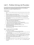
A diagram representing schematically the features of the Embest board is shown in Figure 13. A 8-segment
display
for output
Two LED lights
for output
Two buttons for input
Left
Right
A small display screen
for output with 40 columns
and 15 lines available
0
1
2
3
4
5
6
7
8
9
10
11
12
13
14
15
A Keyboard for input
Figure 13: A diagrammatic view of the available controls and displays on the
Embest Board View
There are 5 main components in this view available for programming:
1. One 8-segment display (output).
2. Two red LED lights (output).
24
ARMSim User Guide
3. Two black buttons (input).
4. Sixteen blue buttons arranged in a keyboard 4 x 4 grid (input).
5. One LCD display screen, which is a grid of 40 columns by 15 rows of individual cells. The coordinates for each LCD cell are specified by a {column, row} pair. The top-left cell has coordinates {0,0},
while the bottom-right cell has coordinates {39,14}. Each cell can contain exactly one ASCII character.
Table 5. SWI operations greater than 0xFF as currently used for the Embest board Plug‐In Opcode
Description and Action
Inputs
Outputs
swi 0x200
Light up the 8‐Segment Display. r0: the 8‐segment Pattern The appropriate segments light (see below in Figure 14 for up to display a number or a details)
character
swi 0x201
Light up the two LEDs .
r0: the LED Pattern, where:
Left LED on = 0x02
Right LED on = 0x01
Both LEDs on = 0x03
(i.e. the bits in position 0 and 1 of r0 must each be set to 1 appropriately)
swi 0x202
Check if one of the Black None
Buttons has been pressed.
r0 = the Black Button Pattern, where:
Left black button pressed returns r0 = 0x02;
Right black button pressed returns r0 = 0x01;
(i.e. the bits in position 0 and 1 of r0 get assigned the appropri‐
ate values).
swi 0x203
Check if one of the Blue None (see below in Fig‐
Buttons has been pressed. ure for details)
r0 = the Blue Button Pattern (see below in Figure ).
swi 0x204
Display a string on the LCD screen
Either the left LED is on, or the right, or both
r0: x position coordinate The string is displayed starting on the LCD screen (0‐39); at the given position of the LCD r1: y position coordinate screen.
on the LCD screen (0‐14);
r2: Address of a null ter‐
minated ASCII string.
Note: (x,y) = (0,0) is the top left and (0,14) is the bot‐
tom left. The display is limited to 40 characters per line.
25
ARMSim# User Guide
Table 5. SWI operations greater than 0xFF as currently used for the Embest board Plug‐In Opcode
Description and Action
Inputs
Outputs
swi 0x205
Display an integer on the LCD screen
r0: x position coordinate The string is displayed starting on the LCD screen (0‐39); at the given position of the LCD r1: y position coordinate screen.
on the LCD screen (0‐14);
r2: integer to print.
Note: (x,y) = (0,0) is the top left and (0,14) is the bot‐
tom left. The display is limited to 40 characters per line
swi 0x206
Clear the display on the LCD screen
None
swi 0x207
Display a character on the r0: x position coordinate The string is displayed starting LCD screen
on the LCD screen (0‐39); at the given position of the LCD r1: y position coordinate screen.
on the LCD screen (0‐14);
r2: the character.
Note: (x,y) = (0,0) is the top left and (0,14) is the bot‐
tom left. The display is limited to 40 characters per line
swi 0x208
Clear one line in the dis‐
play on the LCD screen
Blank LCD screen.
r0: line number (y coordi‐ Blank line on the LCD screen.
nate) on the LCD screen
9.0.1 Detailed Descriptions and Examples for SWI Codes for the Embest Board Plug‐in
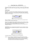
♦ Set the 8‐Segment Display to light up: swi 0x200
The appropriate segments light up to display a number or a character. The pattern of segments to be lit up is assigned to register R0 before the call to swi 0x200. Figure 14 shows the arrangements of seg‐
ments, and an example follows. Each segment is logically labelled and its byte code is shown in the list in Table 6. For example, in Figure 14, to display the number “3”, segments “A”, “B”, “C”, “D” and “F” must be illuminated. The code to be assigned to R0 is computed by the logical OR of the individual byte codes. 26
ARMSim User Guide
Figure 14. The Pattern for the 8‐Segment Display
A
G
Display byte
values
B
F
E
C
D
Example: number “3” plus “dot”
Table 6: Segmen
t byte values
P
A
0x80
B
0x40
C
0x20
P
0x10
D
0x08
E
0x04
F
0x02
G
0x01
As an example, the number 3 plus the right hand dot would have a pattern value computed as the logical OR of the values of the segments “A,B,C,D,F,P” to form the integer: 0x80 | 0x40 |
0x20 | 0x08 | 0x02 | 0x10 =
0xFA, to be assigned to r0.
Below some segments of code are shown as examples for the 8‐segment Display. The “.equ” statements are useful for accessing the byte values associated with the labels of each segment as shown in Figure 14. An example of a possible declaration of data is also given in Figure 16 for the display of integers, where the byte values representing a particular number are already “ORed” together within the array data structure and can be indexed appropriately. It may be easier to use a data declaration for an array of words and then index into it. Each element can be initialized to contain the value representing a number by having the appropriate byte values “ORed” together.
Use “.equ” statements to set up the byte value of each segment of the Display.
.equ
.equ
.equ
.equ
.equ
.equ
.equ
.equ
SEG_A,0x80
SEG_B,0x40
SEG_C,0x20
SEG_D,0x08
SEG_E,0x04
SEG_F,0x02
SEG_G,0x01
SEG_P,0x10
Figure 15: Possible data declaration for byte values for segments
27
ARMSim# User Guide
A possible data dec‐
laration for an array of words which can be indexed to obtain the appropriate value for a number {0,...,9} to be dis‐
played. Digits:
.word
.word
.word
.word
.word
.word
.word
.word
.word
.word
.word
SEG_A|SEG_B|SEG_C|SEG_D|SEG_E|SEG_G @0
SEG_B|SEG_C
@1
SEG_A|SEG_B|SEG_F|SEG_E|SEG_D @2
SEG_A|SEG_B|SEG_F|SEG_C|SEG_D @3
SEG_G|SEG_F|SEG_B|SEG_C @4
SEG_A|SEG_G|SEG_F|SEG_C|SEG_D @5
SEG_A|SEG_G|SEG_F|SEG_E|SEG_D|SEG_C @6
SEG_A|SEG_B|SEG_C
@7
SEG_A|SEG_B|SEG_C|SEG_D|SEG_E|SEG_F|SEG_G @8
SEG_A|SEG_B|SEG_F|SEG_G|SEG_C @9
0
@Blank display
Figure 16: Possible data declaration forinteger patterns
An example of a possible routine to display a number in the 8‐segment Display using the declarations given above is shown in Figure 17. Register R0 and R1 are input parameters, where R0 contains the integer to be displayed and R1 contains “1” to display the “P” segment, or “0” otherwise.
@ *** Display8Segment (Number:R0; Point:R1) ***
@ Displays the number 0-9 in R0 on the
@ LED 8-segment display
@ If R1 = 1, the point is also shown
[1]Display8Segment:
stmfd
sp!,{r0-r2,lr}
[2]
ldr
r2,=Digits
[3]
ldr
r0,[r2,r0,lsl#2]
[4]
tst
r1,#0x01
@if r1=1,
[5]
orrne
r0,r0,#SEG_P
@then show “P”
[6]
swi
0x200
[7]
ldmfd
sp!,{r0-r2,pc}
Figure 17: A possible “Display8Segment” routine
In line [3], register r0 is assigned the byte value corresponding to the indexed element of the array digits from Figure 16. For example, to display the number “3”, after execution of line [2], the input register r0 should contain the integer value 3 and register r2 contains the address of the array “Digits” . Then the computation implied by “[r2,r0,lsl#2]” adds 12 bytes to the address currently in r2 (i.e. r0 shifted left by 2 positions, which evaluates to “3” x 4 = 12) and loads the word in position 3 of the array, namely: .word SEG_A|SEG_B|SEG_F|SEG_C|SEG_D. In fact, this uses the segments “A,B,C,D,F” to display the correct number. In line [4] the content of r1 is tested. If r1 = 1 then the segment “P” is added to the display, with its value ORed with the previous ones in r0.
28
ARMSim User Guide
♦ Set the two LEDs to light up: swi 0x201
Light up the LEDs: the left or the right or both, according to the value supplied by r0.
mov
swi
mov
swi
mov
swi
r0,#0x02
0x201
r0,#0x01
0x201
r0,#0x03
0x201
@ left LED on
@ right LED on
@ both LEDs on
♦ Check if one of the Black Buttons has been pressed: swi 0x202
The call with swi 0x202 sets the content of r0
as:r0=2 if the left black button was pressed or r0=1, if the right black button was pressed. Test‐
ing r0 enables follow up actions.
swi
cmp
beq
bal
0x202
r0,#0x02
ActOnLeftBlack
ActOnRightBlack
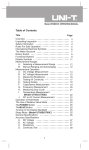
♦ Check if one of the Blue Buttons has been pressed: swi 0x203
After the call with swi 0x203, test the content of r0. The number in r0 corresponds to the posi‐
tion of the blue button as depicted in Figure . For example, if r0=2 then the blue button in posi‐
tion 2 was pressed.
0
1
2
3
4
5
6
7
8
9
10
11
12
13
14
15
swi
0x203
cmp
r0,#1
cmp
r0,#2
cmp
r0,#3
. . . . .
The keypad with 16 blue buttons as depicted in the board view.
A Keyboard for input
They are arranged such that each button has a corresponding bit position in the 16‐bit lower portion of a word in register R0 after the call to swi 0x203 to poll the keypad. The “number labels” placed in the figure, which do not appear on the real keypad, also represent the corresponding bit position as returned in R0. When a button is pressed, the corresponding bit is set. For example, when the button in position “1” is pressed, the swi 0x203 instruction returns r0 =
0x02, that is, r0 = 0 0 0 0 0 0 0 0 0 0 0 0 0 0 0 0 0 0 0 0 0 0 0 0 0 0 0 0 0 0 1 0
in binary, where the bit in position “1” has been set.
Figure 18. The Pattern for the Blue Buttons
29
ARMSim# User Guide
♦ Display a string on the LCD screen: swi 0x204
Display the string whose address is supplied in r2 on the LCD screen at position (x,y), where r0=x and r1=y. In this example, r0=4 and r1=y=1 (that is, line 1 at column 4)
mov r0,#4
mov r1,#1
ldr r2,=Message
swi 0x204
@ display message
...
Message: .asciz "Hello There\n"
♦ Display an integer on the LCD screen: swi 0x205
Display an integer on the LCD screen. The inte‐
ger is in r2, to be shown at position (x,y), where r0=x and r1=y. In this example, r2=23, r0=4 and r1=y=1 (that is, line 1 at column 4 displays 23)
mov
mov
mov
swi
r0,#4
r1,#1
r2,#23
0x205
@ display integer
♦ Clear the display on the LCD screen: swi 0x206 Clear the whole LCD screen.
swi
0x206
@ clear screen
♦ Display a character on the LCD screen: swi 0x207
Display a character on the LCD screen. The char‐
acter is in r2, to be shown at position (x,y), where here r0=x and r1=y. In this example, r2=’Z, r0=4 and r1=y=1 (that is, line 1 at column 4 displays Z).
mov
mov
mov
swi
r0,#4
r1,#1
r2,#’Z
0x207
@display char
♦ Clear one line in the display on the LCD screen: swi 0x208
Clear only one line on the LCD screen, where the line number is given in r0.
ldr
swi
r0,#5
0x208
@clear line 5
10. Code Examples
10.1 Example: Print Strings, Characters and Integers to Stdout using SWI Instructions for I/O
@@@ PRINT STRINGS, CHARACTERS, INTEGERS TO STDOUT
.equ SWI_PrChr,0x00
@ Write an ASCII char to Stdout
.equ SWI_PrStr, 0x69 @ Write a null-ending string
.equ SWI_PrInt,0x6b
@ Write an Integer
.equ Stdout, 1
@ Set output mode to be Output View
.equ SWI_Exit, 0x11
@ Stop execution
.global _start
.text
_start:
@ print a string to Stdout
mov R0,#Stdout
@ mode is Stdout
30
ARMSim User Guide
ldr R1, =Message1
@ load address of Message1
swi SWI_PrStr
@ display message to Stdout
@ print a new line as a string to Stdout
mov R0,#Stdout
@ mode is Stdout
ldr r1, =EOL
@ end of line
swi SWI_PrStr
@ print a character to the screen
mov R0, #'A
@ R0 = char to print
swi SWI_PrChr
@ print a blank character (from data)
ldr r0,=Blank
ldrb r0,[r0]
@ R0 = char to print = blank
swi SWI_PrChr
@ print a second character to Stdout
mov R0, #'B
@ R0 = char to print
swi SWI_PrChr
@ print a new line as a character to Stdout
ldr r0,=NewL
ldrb r0,[r0]
@ R0 = char to print = new line
swi SWI_PrChr
@ print an integer to Stdout
mov R0,#Stdout
@ mode is Output view
mov r1, #42
@ integer to print
swi SWI_PrInt
@ print a new line as a string to Stdout
mov R0,#Stdout
@ mode is Output view
ldr r1, =EOL
@ end of line
swi SWI_PrStr
swiSWI_Exit @ stop executing: end of program
.data
Message1: .asciz"Hello World!"
EOL:
.asciz
"\n"
NewL:
.ascii
"\n"
Blank:
.ascii
" "
.end
10.2 Example: Open and close files, read and print integers using SWI Instructions for I/O
@@@ OPEN INPUT FILE, READ INTEGER FROM FILE, PRINT IT, CLOSE INPUT FILE
.equ SWI_Open, 0x66
@open a file
.equ SWI_Close,0x68
@close a file
.equ SWI_PrChr,0x00
@ Write an ASCII char to Stdout
.equ SWI_PrStr, 0x69
@ Write a null-ending string
.equ SWI_PrInt,0x6b
@ Write an Integer
.equ SWI_RdInt,0x6c
@ Read an Integer from a file
.equ Stdout, 1
@ Set output target to be Stdout
.equ SWI_Exit, 0x11
@ Stop execution
.global _start
.text
_start:
@ print an initial message to the screen
31
ARMSim# User Guide
mov R0,#Stdout
@print an initial message
ldr R1, =Message1
@ load address of Message1 label
swi SWI_PrStr
@ display message to Stdout
@ == Open an input file for reading =============================
@ if problems, print message to Stdout and exit
ldr r0,=InFileName
@ set Name for input file
mov r1,#0
@ mode is input
swi SWI_Open
@ open file for input
bcs InFileError
@ Check Carry-Bit (C): if= 1 then ERROR
@ Save the file handle in memory:
ldr r1,=InputFileHandle
@ if OK, load input file handle
str r0,[r1]
@ save the file handle
@ == Read integers until end of file =============================
RLoop:
ldr r0,=InputFileHandle
@ load input file handle
ldr r0,[r0]
swi SWI_RdInt
@ read the integer into R0
bcs EofReached
@ Check Carry-Bit (C): if= 1 then EOF reached
@ print the integer to Stdout
mov r1,r0
@ R1 = integer to print
mov R0,#Stdout
@ target is Stdout
swi SWI_PrInt
mov R0,#Stdout
@ print new line
ldr r1, =NL
swi SWI_PrStr
bal RLoop
@ keep reading till end of file
@ == End of file ===============================================
EofReached:
mov R0, #Stdout
@ print last message
ldr R1, =EndOfFileMsg
swi SWI_PrStr
@ == Close a file ===============================================
ldr R0, =InFileHandle
@ get address of file handle
ldr R0, [R0]
@ get value at address
swi SWI_Close
Exit:
swiSWI_Exit
@ stop executing
InFileError:
mov R0, #Stdout
ldr R1, =FileOpenInpErrMsg
swi SWI_PrStr
bal Exit
@ give up, go to end
.data
.align
InFileHandle:
.skip
4
InFileName:
.asciz
"whatever.txt"
FileOpenInpErrMsg: .asciz "Failed to open input file \n"
EndOfFileMsg:
.asciz
"End of file reached\n"
ColonSpace:
.asciz": "
NL:
.asciz
"\n "
@ new line
32
ARMSim User Guide
Message1:
.end
.asciz
"Hello World! \n"
10.3 Example: Useful patterns for using SWI Instructions for a Plug‐In
This is a possible initial template to set the useful SWI codes for the Embest Board Plug‐in
.equ SWI_SETSEG8,
0x200
@display on 8 Segment
.equ SWI_SETLED,
0x201
@LEDs on/off
.equ SWI_CheckBlack, 0x202
@check Black button
.equ SWI_CheckBlue,
0x203
@check press Blue button
.equ SWI_DRAW_STRING, 0x204
@display a string on LCD
.equ SWI_DRAW_INT,
0x205
@display an int on LCD
.equ SWI_CLEAR_DISPLAY,0x206
@clear LCD
.equ SWI_DRAW_CHAR,
0x207
@display a char on LCD
.equ SWI_CLEAR_LINE, 0x208
@clear a line on LCD
.equ SWI_EXIT,
0x11
@terminate program
.equ SWI_GetTicks,
0x6d
@get current time
.equ SEG_A, 0x80
@ patterns for 8 segment display
.equ SEG_B, 0x40
@byte values for each segment
.equ SEG_C, 0x20
@of the 8 segment display
.equ SEG_D, 0x08
.equ SEG_E, 0x04
.equ SEG_F, 0x02
.equ SEG_G, 0x01
.equ SEG_P, 0x10
.equ LEFT_LED,
0x02
@bit patterns for LED lights
.equ RIGHT_LED,
0x01
.equ LEFT_BLACK_BUTTON,0x02
@bit patterns for black buttons
.equ RIGHT_BLACK_BUTTON,0x01
@and for blue buttons
.equ BLUE_KEY_00, 0x01
@button(0)
.equ BLUE_KEY_01, 0x02
@button(1)
.equ BLUE_KEY_02, 0x04
@button(2)
.equ BLUE_KEY_03, 0x08
@button(3)
.equ BLUE_KEY_04, 0x10
@button(4)
.equ BLUE_KEY_05, 0x20
@button(5)
.equ BLUE_KEY_06, 0x40
@button(6)
.equ BLUE_KEY_07, 0x80
@button(7)
.equ BLUE_KEY_00, 1<<8
@button(8) - different way to set
.equ BLUE_KEY_01, 1<<9
@button(9)
.equ BLUE_KEY_02, 1<<10
@button(10)
.equ BLUE_KEY_03, 1<<11
@button(11)
.equ BLUE_KEY_04, 1<<12
@button(12)
.equ BLUE_KEY_05, 1<<13
@button(13)
.equ BLUE_KEY_06, 1<<14
@button(14)
.equ BLUE_KEY_07, 1<<15
@button(15)
10.4 Example: Subroutine to implement a wait cycle with the 32‐bit timer
@ Wait(Delay:r2) wait for r2 milliseconds
Wait:
stmfdsp!, {r0-r1,lr}
33
ARMSim# User Guide
swi SWI_GetTicks
mov r1, r0
WaitLoop:
swi SWI_GetTicks
subs r0, r0, r1
rsbltr0, r0, #0
cmp r0, r2
blt WaitLoop
WaitDone:
ldmfdsp!, {r0-r1,pc}
@ R1: start time
@ R0: time since start
@ fix unsigned subtract
10.5 Example: Subroutine to check for an interval with a 15‐bit timer (Embest Board)
The timer in ARMSim# is implemented using a 32‐bit quantity and the current time (as number of ticks) is accessed by using the SWI instruction with operand 0x6d (the corresponding EQU is set to be SWI_GetTicks). It returns in R0 the number of ticks in milliseconds. On the other hand, the timer on the Embest board uses only a 15‐bit quantity and this can cause a problem with rollover. Assume one checks the time at a starting point T1 and then later at point T2, and one needs to test whether a certain amount of time has passe. Ideally computing T2‐T1 and comparing it to the desired interval is enough. The range in ARMSim# with a 32‐bit timer is between 0 and 232 ‐1 = 4,294,967,295. As milliseconds, this gives a range of about 71,582 minutes, which is normally enough to ensure that one can keep checking the intervals T2‐T1 without T2 ever going out of range in a single program execution. The range in the Embest board with a 15‐bit timer is between 0 and 215‐1 = 32,767, giving a range of only 32 seconds. When checking the interval T2‐T1, there is no problem as long as T2>T1 and T2<32,767. However it can happen that T1 is obtained close to the top of the range and T1 subsequently has a value after the rollover, thus T2<T1. It is not enough to flip the sign as the following examples show.
Let T1 = 1,000 and T2 = 15,000. Then T2‐T1 = 14,000 gives the correct answer for the interval. Subse‐
quently let T1= 30,000 and the later T2 = 2,000 (afte the timer has rolled over). If one simply calculates T2‐
T1 = ‐28,000 or even tries to get its absolute value, the answer is incorrect. The value for the interval should be: (32,767 ‐ T1) + T2 = 32,767 ‐30,000 + 2,000 = 4,767, which represents the correct number of ticks which passed between T1 and T2. Two things need to be done for correct programming. First of all the timing value obtained in 32 bits in ARMSim# should be “masked” to be only a 15 bit quantity, so that the code will work both in the simula‐
tor and on the board. Secondly, the testing for the interval include a test for rollover.
.equ Sec1, 1000
@ 1 seconds interval
.equ Point1Sec, 100
@ 0.1 seconds interval
.equ EmbestTimerMask, 0x7fff
@ 15 bit mask for timer values
.equ Top15bitRange,0x0000ffff
@(2^15) -1 = 32,767
.text
_start:
movr6,#0
@ counting the loops (not necessary)
ldrr8,=Top15bitRange
ldrr7,=EmbestTimerMask
ldrr10,=Point1Sec
SWISWI_GetTicks @Get current time T1
movr1,r0
@ R1 is T1
andr1,r1,r7
@ T1 in 15 bits
RepeatTillTime:
addr6,r6,#1
@ count number of loops (not necessary)
34
ARMSim User Guide
SWISWI_GetTicks @Get current time T2
movr2,r0
@ R2 is T2
andr2,r2,r7
@ T2 in 15 bits
cmpr2,r1
@ is T2>T1?
bgesimpletime
subr9,r8,r1
@ TIME= 32,676 - T1
addr9,r9,r2
@
+ T2
balCheckInt
simpletime:
subr9,r2,r1
@ TIME = T2-T1
CheckInt:
cmpr9,r10
@is TIME < interval?
bltRepeatTillTime
swiSWI_EXIT
.end
10.6 swiSWI_EXITExample: Using the SWI Instructions for a Plug‐In (Embest Board View)
@ Demonstration of Embest S3CE40 development board view
@ ===== Assume the EQU declaration from previous examples
@Clear the board, clear the LCD screen
swi SWI_CLEAR_DISPLAY
@Both LEDs off
mov r0,#0
swi SWI_SETLED
@8-segment blank
mov r0,#0
swi SWI_SETSEG8
@draw a message to the lcd screen on line#1, column 4
mov r0,#4
@ column number
mov r1,#1
@ row number
ldr r2,=Welcome @ pointer to string
swi SWI_DRAW_STRING @ draw to the LCD screen
@display the letter H in 7segment display
ldr r0,=SEG_B|SEG_C|SEG_G|SEG_E|SEG_F
swi SWI_SETSEG8
@turn on LEFT led and turn off RIGHT led
mov r0,#LEFT_LED
swi SWI_SETLED
@draw a message to the lcd screen on line#2, column 4
mov r0,#4
@ column number
mov r1,#2
@ row number
ldr r2,=LeftLED @ pointer to string
swi SWI_DRAW_STRING @ draw to the LCD screen
@Wait for 3 second
ldr r3,=3000
BL Wait
@turn on RIGHT led and turn off LEFT led
mov r0,#RIGHT_LED
swi SWI_SETLED
@draw a message to the lcd screen on line#2, column 4
35
ARMSim# User Guide
mov r0,#4
@ column number
mov r1,#2
@ row number
ldr r2,=RightLED @ pointer to string
swi SWI_DRAW_STRING @ draw to the LCD screen
@Wait for 3 second
ldr r3,=3000
BL Wait
@turn on both led
mov r0,#(LEFT_LED|RIGHT_LED)
swi SWI_SETLED
@clear previous line 2
mov r0,#2
swi SWI_CLEAR_LINE
@draw a message to inform user to press a black button
mov r0,#6
@ column number
mov r1,#2
@ row number
ldr r2,=PressBlackL @ pointer to string
swi SWI_DRAW_STRING @ draw to the LCD screen
@wait for user to press a black button
mov r0,#0
LB1:
swi SWI_CheckBlack
@get button press into R0
cmp r0,#0
beq LB1
@ if zero, no button pressed
cmp r0,#RIGHT_BLACK_BUTTON
bne LD1
ldr r0,=SEG_B|SEG_C|SEG_F @right button, show -|
swi SWI_SETSEG8
mov r0,#RIGHT_LED
@turn on right led
swi SWI_SETLED
bal NextButtons
LD1:
@left black pressed
ldr r0,=SEG_G|SEG_E|SEG_F
@display |- on 8segment
swi SWI_SETSEG8
mov r0,#LEFT_LED
@turn on LEFT led
swi SWI_SETLED
NextButtons:
@Wait for 3 second
ldr r3,=3000
BL Wait
@Test the blue buttons 0-9 with prompting, then display
@number on 8-segment for 3 seconds. If >9, invalid.
@Draw a message to inform user to press a blue button
mov r0,#2
@clear previous line 2
swi SWI_CLEAR_LINE
mov r0,#6
@ column number
mov r1,#2
@ row number
ldr r2,=PressBlue
@ pointer to string
swi SWI_DRAW_STRING @ draw to the LCD screen
mov r4,#16
36
ARMSim User Guide
BLUELOOP:
@wait for user to press blue button
mov r0,#0
BB1:
swi SWI_CheckBlue
@get button press into R0
cmp r0,#0
beq BB1
@ if zero, no button pressed
cmp r0,#BLUE_KEY_15
beq FIFTEEN
cmp r0,#BLUE_KEY_14
beq FOURTEEN
cmp r0,#BLUE_KEY_13
beq THIRTEEN
cmp r0,#BLUE_KEY_12
beq TWELVE
cmp r0,#BLUE_KEY_11
beq ELEVEN
cmp r0,#BLUE_KEY_10
beq TEN
cmp r0,#BLUE_KEY_09
beq NINE
cmp r0,#BLUE_KEY_08
beq EIGHT
cmp r0,#BLUE_KEY_07
beq SEVEN
cmp r0,#BLUE_KEY_06
beq SIX
cmp r0,#BLUE_KEY_05
beq FIVE
cmp r0,#BLUE_KEY_04
beq FOUR
cmp r0,#BLUE_KEY_03
beq THREE
cmp r0,#BLUE_KEY_02
beq TWO
cmp r0,#BLUE_KEY_01
beq ONE
cmp r0,#BLUE_KEY_00
mov r0,#5
@clear previous line
swi SWI_CLEAR_LINE
mov r1,#0
mov r0,#0
BL Display8Segment
bal CKBLUELOOP
ONE:
mov r0,#5
@clear previous line
swi SWI_CLEAR_LINE
mov r1,#0
mov r0,#1
BL Display8Segment
37
ARMSim# User Guide
bal CKBLUELOOP
TWO:
mov
swi
mov
mov
BL
bal
THREE:
mov
swi
mov
mov
BL
bal
FOUR:
mov
swi
mov
mov
BL
bal
FIVE:
mov
swi
mov
mov
BL
bal
SIX:
mov
swi
mov
mov
BL
bal
SEVEN:
mov
swi
mov
mov
BL
bal
EIGHT:
mov
swi
mov
mov
BL
bal
38
r0,#5
@clear previous line
SWI_CLEAR_LINE
r1,#0
r0,#2
Display8Segment
CKBLUELOOP
r0,#5
@clear previous line
SWI_CLEAR_LINE
r1,#0
r0,#3
Display8Segment
CKBLUELOOP
r0,#5
@clear previous line
SWI_CLEAR_LINE
r1,#0
r0,#4
Display8Segment
CKBLUELOOP
r0,#5
@clear previous line
SWI_CLEAR_LINE
r1,#0
r0,#5
Display8Segment
CKBLUELOOP
r0,#5
@clear previous line
SWI_CLEAR_LINE
r1,#0
r0,#6
Display8Segment
CKBLUELOOP
r0,#5
@clear previous line
SWI_CLEAR_LINE
r1,#0
r0,#7
Display8Segment
CKBLUELOOP
r0,#5
@clear previous line
SWI_CLEAR_LINE
r1,#0
r0,#8
Display8Segment
CKBLUELOOP
ARMSim User Guide
NINE:
mov r0,#5
@clear previous line
swi SWI_CLEAR_LINE
mov r1,#0
mov r0,#9
BL Display8Segment
bal CKBLUELOOP
TEN:
mov r0,#5
@clear previous line
swi SWI_CLEAR_LINE
mov r0,#6
@ column number
mov r1,#5
@ row number
ldr r2,=InvBlue
@ pointer to string
swi SWI_DRAW_STRING @ draw to the LCD screen
mov r1,#0
mov r0,#10
@ clear 8-segment
BL Display8Segment
bal CKBLUELOOP
ELEVEN:
mov r0,#5
@clear previous line
swi SWI_CLEAR_LINE
mov r0,#6
@ column number
mov r1,#5
@ row number
ldr r2,=InvBlue
@ pointer to string
swi SWI_DRAW_STRING @ draw to the LCD screen
mov r1,#0
mov r0,#10
@ clear 8-segment
BL Display8Segment
bal CKBLUELOOP
TWELVE:
mov r0,#5
@clear previous line
swi SWI_CLEAR_LINE
mov r0,#6
@ column number
mov r1,#5
@ row number
ldr r2,=InvBlue
@ pointer to string
swi SWI_DRAW_STRING @ draw to the LCD screen
mov r1,#0
mov r0,#10
@ clear 8-segment
BL Display8Segment
bal CKBLUELOOP
THIRTEEN:
mov r0,#5
@clear previous line
swi SWI_CLEAR_LINE
mov r0,#6
@ column number
mov r1,#5
@ row number
ldr r2,=InvBlue
@ pointer to string
swi SWI_DRAW_STRING @ draw to the LCD screen
mov r1,#0
mov r0,#10
@ clear 8-segment
BL Display8Segment
39
ARMSim# User Guide
bal CKBLUELOOP
FOURTEEN:
mov r0,#5
@clear previous line
swi SWI_CLEAR_LINE
mov r0,#6
@ column number
mov r1,#5
@ row number
ldr r2,=InvBlue
@ pointer to string
swi SWI_DRAW_STRING @ draw to the LCD screen
mov r1,#0
mov r0,#10
@ clear 8-segment
BL Display8Segment
bal CKBLUELOOP
FIFTEEN:
mov r0,#5
@clear previous line
swi SWI_CLEAR_LINE
mov r0,#6
@ column number
mov r1,#5
@ row number
ldr r2,=InvBlue
@ pointer to string
swi SWI_DRAW_STRING @ draw to the LCD screen
mov r1,#0
mov r0,#10
@ clear 8-segment
BL Display8Segment
CKBLUELOOP:
mov r0,#10
@clear previous line
swi SWI_CLEAR_LINE
mov r0,#4
@clear previous line
swi SWI_CLEAR_LINE
mov r0,#1
@ display number of tests
mov r1,#4
ldr r2,=TestBlue
swi SWI_DRAW_STRING
mov r0,#10
mov r1,#4
mov r2,r4
swi SWI_DRAW_INT
subs r4,r4,#1
bne BLUELOOP
@give only 15 tests
@Prepare to exit: lst message and clear the board
@draw a message to the lcd screen on line#10, column 1
mov r0,#1
@ column number
mov r1,#10
@ row number
ldr r2,=Bye
@ pointer to string
swi SWI_DRAW_STRING @ draw to the LCD screen
@Turn off both LED's
ldr r0,=0
swi SWI_SETLED
@8-segment blank
mov r0,#0
swi SWI_SETSEG8
ldr r3,=2000
@delay a bit
40
ARMSim User Guide
BL Wait
@Clear the LCD screen
swi SWI_CLEAR_DISPLAY
swi SWI_EXIT
@all done, exit
@ ===== Display8Segment (Number:R0; Point:R1)
@ Displays the number 0-9 in R0 on the 8-segment display
@ If R1 = 1, the point is also shown
Display8Segment:
stmfd
sp!,{r0-r2,lr}
ldr
r2,=Digits
ldr
r0,[r2,r0,lsl#2]
tst
r1,#0x01 @if r1=1,
orrne
r0,r0,#SEG_P
@then show P
swi
SWI_SETSEG8
ldmfd
sp!,{r0-r2,pc}
@ ===== Wait(Delay:r3) wait for r3 milliseconds
@ Delays for the amount of time stored in r3 for a 15-bit timer
Wait:
stmfd
sp!,{r0-r5,lr}
ldr
r4,=0x00007FFF
@mask for 15-bit timer
SWI
SWI_GetTicks
@Get start time
and
r1,r0,r4
@adjusted time to 15-bit
Wloop:
SWI
SWI_GetTicks
@Get current time
and
r2,r0,r4
@adjusted time to 15-bit
cmp
r2,r1
blt
Roll
@rolled above 15 bits
sub
r5,r2,r1
@compute easy elapsed time
bal
CmpLoop
Roll: sub
r5,r4,r1
@compute rolled elapsed time
add
r5,r5,r2
CmpLoop:cmp r5,r3
@is elapsed time < delay?
blt
Wloop
@Continue with delay
Xwait:ldmfd sp!,{r0-r5,pc}
@ ================================================
.data
Welcome:
.asciz
"Welcome to Board Testing"
LeftLED:
.asciz
"LEFT light"
RightLED:
.asciz
"RIGHT light"
PressBlackL: .asciz
"Press a BLACK button"
Bye:
.asciz
"Bye for now."
Blank:
.asciz
" "
Digits:
.word SEG_A|SEG_B|SEG_C|SEG_D|SEG_E|SEG_G @0
.word SEG_B|SEG_C @1
.word SEG_A|SEG_B|SEG_F|SEG_E|SEG_D @2
.word SEG_A|SEG_B|SEG_F|SEG_C|SEG_D @3
.word SEG_G|SEG_F|SEG_B|SEG_C @4
.word SEG_A|SEG_G|SEG_F|SEG_C|SEG_D @5
.word SEG_A|SEG_G|SEG_F|SEG_E|SEG_D|SEG_C @6
41
ARMSim# User Guide
.word SEG_A|SEG_B|SEG_C @7
.word SEG_A|SEG_B|SEG_C|SEG_D|SEG_E|SEG_F|SEG_G @8
.word SEG_A|SEG_B|SEG_F|SEG_G|SEG_C @9
.word 0 @Blank display
PressBlue:
.asciz
"Press a BLUE button 0-9 only - 15 tests"
InvBlue:
.asciz
"Invalid blue button - try again"
TestBlue:
.asciz
"Tests ="
.end
42