Download TC-TP1 Net Probe User's Guide
Transcript
TC-TP1 Net Probe
Amplified Inductor and Tone Probe
User’s Guide
WARNING
!
Never connect this Probe to a live wire from a non-compatible
telephone/network system. Doing so may damage the Probe
and/or the equipment.
Please observe and follow all safety protocols to avoid injuries.
A. Description
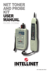
The Net Probe is a feature packed tone tracer. It is ergonomically designed to fit in the hand of
the operator. The Probe can also accept a 2.5mm earphone to help the operator listening to
the tone in a noisy environment. When combined with a compatible cable tester with built-in
tone generator, you can trace and test a cable swiftly. The Net Probe has a RJ-45 connector;
you can use it to quickly detect voltage on the center pair or exam telephone line’s polarity. On
the back of the Net Probe, there are two test pins for clip leads to quickly access RJ-45 jack’s
middle pins (Pin 4 and 5). The tip on the Net Probe is also replaceable and the lanyard
provides quick access to the Probe. The Net Probe is compatible with most Tone Generators
on the market, making it one of the best investments in your toolbox.
B. Tone Tracing Instruction
To use the Net Probe, you must first install a compatible Tone Generator/Tester.
Connect the Tone Generator to the test cable (please refer to the manufacturer’s manual). If
the use of a 2.5mm earphone is preferred, connect a compatible earphone to the Probe’s
Earphone Jack and set audio output selector from speaker to earphone. The Net Probe is also
equipped with a LED “Signal” indicator to provide a visual feedback when detecting tone.
1.
2.
3.
4.
5.
6.
Locate the battery compartment on the back of the Probe.
Push the triangle marking on the cover and push it away from the Probe. The
cover should slide away to reveal the battery compartment.
Connect a fresh 9V DC battery t the connector and slide the cover back to close
the compartment.
Set the “TEL/TRACE” selector on the left hand side of the Probe to “TRACE?”
position.
Point the tip of the Probe to the cables that you are testing and push and hold the
“TRACE” button to trace a line.
You can also connect a RJ-11 or RJ-45 jumper cable from the Probe’s RJ-45 jack
to a wall jack to test its polarity.
i.
Tracing (for unknown cable path/termination) – Adjust gain (volume) control to
the desired level and begin tracing from the tone generator location. Adjust the
volume (gain) control to maintain a constant tone. Trace over the entire path of the
test cable or until the cable end is located.
ii.
Locating (termination verification/general area of termination) – Adjust gain
(volume) control to the maximum level. Begin tracing in the general area of the
cable termination. Zigzag the Probe slowly and exam the entire area. Avoid any
high voltage sources and adjust the gain control when necessary to maintain a
constant tone.
iii. Locating (conductor break/discontinuity) – Adjust gain (volume) control to
“medium ~ low” level. Begin tracing the cable starting from the tone generator.
1
Continue tracing along the cable and when the tone disappear, the location of the
Probe is where the cable break. Adjust the gain control to “high” level to pinpoint
isolate the location of the break.
Note: The tone is at its loudest when the tip of the probe is near and
parallel to the cable carrying the tone signal.
C. Line Testing Instruction
Use this function on the compatible “Analogue” telecom and network system only.
1.
2.
Set the “TEL/TRACE” selector to “?TEL” position.
Connect the RJ-45 modular jack on the Net Probe to a wall jack using the jumper
cable.
Check the LED indicators under “TEL”.
3.
i. Identifying telephone line polarity and verifying telephone line’s function.
?? NORM. – This LED lights green when the analog telephone patch cable or the
outlet is installed properly. It indicates the telephone line carries proper
voltage and has correct polarity.
?? REV. – This LED lights yellow when the analog telephone patch cable or the
outlet is wired incorrectly. It indicates the telephone line’s polarity is
reversed.
?
?
?
?
If both NORM. and REV. LEDs are on, the line carries AC current (abnormal).
Disconnect from the line and proceed with caution. If one of the LEDs is on
solid, this indicates the presence of DC current.
If both NORM. and REV. LEDs are flashing, the line is ringing. You can use this
feature to verify the phone number.
If one or both NORM. and REV. LEDs are on, electric current is present on the
center pair of the jack (wire 4 and 5 on RJ-45 or wire 3 and 4 on RJ-11 and
RJ-12).
If none of the LEDs lights, the cable is most likely not connected.
ii. Checking low voltage (for AC or DC less than 24 volts)
?
If the REV. LED lights solid yellow, the “+” test lead is connected to the negative
(+) DC pole and the “-“ lead is connect to the “-“ DC pole.
?
If the NORM. LED lights solid green, the “+” test lead is connected to the
negative (-) DC pole and the “-“ lead is connected to the “+” DC pole.
?
Tip Replacement
(1) To replace Probe tip, grab the tip with your fingers and twist it counter clockwise
until the tip comes off.
(2) Replace old tip with a compatible new tip (included) and twist the tip clockwise until
snug. Do not over tighten the tip.
? Low battery indicator
When the battery power is low, the “LOW BATT” LED will light red. Replace the old
battery with a fresh one.
? Battery Replacement
(1) The Net Probe requires one standard Alkaline DC 9 volts or compatible battery.
(2) Slide back the battery cover to replace the old battery with new one.
SS112102
2


