1
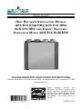
USER GUIDE
HEAT RECOVERY VENTILATORS MODELS
AVS E15 ECM HRV, AVS E15 HRV,
AVS E10 HRV AND ENERGY RECOVERY
VENTILATOR MODEL AVS E15 ECM ERV
PLEASE READ AND SAVE THESE INSTRUCTIONS
Venmar Ventilation ULC, 550 Lemire Blvd., Drummondville, QC, Canada J2C 7W9
www.venmar.ca
These
products
earned
the
ENERGY STAR® by meeting strict
energy efficiency guidelines set by
Natural Resources Canada and the
US EPA. They meet ENERGY STAR
requirements only when used in
Canada.
21782 rev. 03
Congratulations!
You have made an excellent choice! The operating principle of your Heat Recovery Ventilator
or your Energy Recovery Ventilator will give you personal comfort you have never known
before.
We have prepared this User Guide especially for you. Please read it carefully to ensure you
obtain full benefit from your unit. Over the coming months, you will increasingly appreciate the
feeling of living in a more comfortable house.
Please take note that this manual uses the following symbols to emphasize particular
information:
! WARNING
Identifies an instruction which, if not followed, might cause serious
personal injuries including possibility of death.
CAUTION
Identifies an instruction which, if not followed, may severely damage the
unit and/or its components.
NOTE: Indicates supplementary information needed to fully complete an instruction.
We welcome any suggestions you may have concerning this guide and/or the unit, and we
would appreciate hearing your comments on ways to better serve you.
Please forward all correspondence to us at the address indicated on the product registration
card included with this guide.
CAUTION
Make sure at all times that the outdoor intake and exhaust hoods are free
from any snow during the winter season. It is important to check your unit
during a big snow storm, so it doesn’t draw in any snow. If this is the case,
please operate the unit in the recirculation mode, or turn it OFF for a few
hours.
Do not use your unit during construction or renovation of your house or
when sanding drywall. This type of dust may damage your system.
Since the electronic control system of the unit is incorporated with a
microprocessor, it may not operate correctly because of external noise
or very short power failure. If this happens, unplug the unit and wait
approximately 10 seconds. Then, plug the unit in again.
CAUTION
When leaving the house for a long period of time (more than two weeks), a
responsible person should regularly check if the unit operates adequately.
If the ductwork runs through an unconditioned space (e.g.: attic), the unit
must operate continuously except when performing maintenance and/
or repair. Also, the ambient temperature of the house should never drop
below 18°C (65°F). At least once a year, the unit mechanical and electronic
parts should be inspected by qualified service personnel.
2
TABLE OF CONTENTS
1. DEFROSTING MODE
. . . . . . . . . . . . . . . . . . . . . . . 4
2. CONTROLS . . . . . . . . . . . . . . . . . . . . . . . . . . . 4-5
2.1 BOOTING SEQUENCES . . . . . . . . . . . . . . . . . . . . . . . . 4
2.2 INTEGRATED CONTROL . . . . . . . . . . . . . . . . . . . . . . . . 5
2.3 OPTIONAL MAIN AND AUXILIARY CONTROLS . . . . . . . . . . . . . . . 5
3. MAINTENANCE . . . . . . . . . . . . . . . . . . . . . . . . . 6-7
3.1 QUARTERLY MAINTENANCE . . . . . . . . . . . . . . . . . . . . . . . 6
3.2 ANNUAL MAINTENANCE . . . . . . . . . . . . . . . . . . . . . . . 6-7
4. TROUBLESHOOTING . . . . . . . . . . . . . . . . . . . . . . . . 8
REPLACEMENT PARTS AND REPAIR
In order to ensure your ventilation unit remains in good working condition, you must use
Venmar Ventilation ULC genuine replacement parts only. The Venmar Ventilation ULC
genuine replacement parts are specially designed for each unit and are manufactured
to comply with all the applicable certification standards and maintain a high standard of
safety. Any third party replacement part used may cause serious damage and drastically
reduce the performance level of your unit, which will result in premature failing. Venmar
Ventilation ULC also recommends to contact a Venmar Ventilation ULC certified service
depot for all replacement parts and repairs.
3
1. DEFROSTING MODE
When the outdoor temperature is below -5°C (23°F), recovery of heat in HRV units creates
frost in the core. For ERV units, when the outdoor temperature is below -10°C (14°F),
recovery of energy creates frost in the core.
To maintain its proper operation, the unit is programmed to defrost the recovery core. The
defrost frequency varies according to the outdoor temperature.
During the defrost cycle, the unit shifts to maximum speed and the dampers close.
After defrosting, the unit returns to the operating mode selected by the user.
2. CONTROLS
2.1 BOOTING SEQUENCES
BOOTING SEQUENCE (AVS E15 ECM HRV AND AVS E15 ECM ERV ONLY)
The unit booting sequence is similar to a personal computer booting sequence.
Each time the unit is plugged after being unplugged, or a power failure occurs, the unit will
perform a 30-second booting sequence before starting to operate.
During the booting sequence, the integrated control LED will light AMBER for 10 seconds.
After that, the LED will light RED for the rest of the booting sequence. During this RED light
phase, the unit is checking and resetting the motorized damper position.
Once the motorized damper position completely set, the RED light turns off and the booting
sequence is done.
NOTE: No command will be taken until the unit is fully booted.
BOOTING SEQUENCE (AVS E15 HRV AND AVS E10 HRV ONLY)
The unit booting sequence is similar to a personal computer booting sequence.
Each time the unit is plugged after being unplugged, or a power failure occurs, the unit will
perform a 30-second booting sequence before starting to operate.
During the booting sequence, the integrated control LED will light GREEN (unit set in
normal defrost) or AMBER (unit set in extended defrost) for 3 seconds, and then will shut
off for 2 seconds. After that, the LED will light RED for the rest of the booting sequence.
During this RED light phase, the unit is checking and resetting the motorized damper
position.Once the motorized damper position completely set, the RED light turns off and
the booting sequence is done.
NOTE: No command will be taken until the unit is fully booted.
4
2. CONTROLS (CONT’D)
2.2 INTEGRATED CONTROL
All units are equipped with an integrated control, located under the unit, on the recessed side
of electrical compartment. Plug the unit. Use the push button (1) to control the unit. The LED (2)
will then show on which mode the unit is in.
2
VD0207
1
BOTTOM OF THE UNIT
Refer to table below.
LED COLOR
RESULTS
AMBER
UNIT IS ON LOW SPEED
GREEN
UNIT IS ON HIGH SPEED
NO LIGHT
UNIT IS OFF OR CONTROLLED BY A MAIN CONTROL
If a problem occurs during the unit operation, its integrated control LED (2) will blink. The color
of the blinking light depends on the type of error detected. Refer to Section 4 Troubleshooting
on last page for further details.
NOTE: When using main control, the integrated control must be turned off.
2.3 OPTIONAL MAIN AND AUXILIARY CONTROLS
For more convenience, these units can also be controlled using an optional main control.
Only one main control can be connected per unit.
NOTES: 1. The integrated control must be turned OFF to use an optional main control.
2. If an optional auxiliary control is used, its activation will override the main
control operation.
For more information about your unit controls, refer to the Main and auxiliary wall controls
user guide (included with your unit and also available at www.venmar.ca).
5
3. MAINTENANCE
! WARNING
Risk of electric shock. Before performing any maintenance or servicing,
always disconnect the unit from its power source. When cleaning the unit,
it is recommended to wear safety glasses and gloves.
Refer to illustration at right to identify the inner parts of
your unit.
2
1
VD0210
1) HRV or ERV core 2) Core filters
3.1 QUARTERLY MAINTENANCE
1. Turn the unit off and unplug the unit.
A
2. Remove the unit door
following these steps:
B
by
A Remove both door
lower mechanical
screws 8-32 x 1 (1 )and set
aside.
B Open (2) and lift out the
door (3).
3
2
1
VO0149
3. Slide out both filters from the top of the recovery core.
4. Wash both core filters under lukewarm water with mild soap. Rinse thoroughly and let
dry completely before reinstalling on the core.
5. Slide the cleaned filters into the unit.
NOTE: The mesh side of filters must be on bottom (rests on core surface).
6. Reinstall the door. Secure it with both mechanical screws 8-32 x 1” previously removed,
plug back the unit and turn it on.
NOTE: The unit will return to its previous setting after a 30-second delay for booting
sequence.
3.2 ANNUAL MAINTENANCE
Perform steps 1 and 2 of the Quarterly Maintenance (Section 3.1), then continue with the
following steps on next page.
6
3. MAINTENANCE (CONT’D)
3.2 ANNUAL MAINTENANCE (CONT’D)
3. Slide out both filters (3) and recovery
core (4) from the unit.
4. Clean the inside walls of the unit with
a damp cloth, then wipe with a clean
dry one.
5. Wash both core filters under
lukewarm water with mild soap. Rinse
thoroughly and let dry completely
3
before reinstalling on the core.
4
VD0208
6. Clean the core (refer to table below).
Heat Recovery Core Cleaning
Energy Recovery Core Cleaning
Allow the recovery core to soak for 3 hours Remove the dust on the core using
in a solution of warm water and mild soap a vacuum cleaner and a soft brush
(liquid soap).
attachment.
Rinse lightly, let dry and reinstall.
CAUTION
Do not soak the energy recovery core in water. This core can easely be
damaged especially if it is soaked.
7.
Slide the cleaned core into the unit.
CAUTION
Make sure to align proper symbol on the
core (circle or square) with the one on the
unit.
8. Slide the cleaned filters into the unit.
NOTE: The mesh side of filters must be on bottom
(rests on core surface).
VD0209
9. Reinstall the door. Secure it with both mechanical screws 8-32 x 1” previously removed.
10. Clean the exterior hoods, plug back the unit and turn it on.
NOTE: The unit will return to its previous setting after a 30-second delay for booting
sequence.
7
4. TROUBLESHOOTING
If the unit does not work properly, reset the unit by unplugging it for one minute and
then replug it. If it still not working properly, refer to table below. First make sure that
the integrated control is set to OFF (no LED lit).
PROBLEMS
TRY THIS
1.
Nothing works.
• See if the unit is plugged in.
• See if the unit is receiving power from the
house circuit breaker or fuse.
2.
Condensation on windows
(air too humid).
• Operate the unit on maximum speed ventilation
until the situation is corrected.
• Leave curtains half-open to allow air circulation.
• Store all firewood in a closed room with a
dehumidifier or in a well ventilated room, or store
the wood outdoors.
• Do not adjust the thermostat of your heating
system below 18°C (64°F).
3.
Inside air too dry.
• Temporarily use a humidifier.
• Operate the unit in recirculation mode (if available).
4.
Air too cold at the air supply
grille.
• Check if the exterior hood is not blocked.
• Operate the unit in low speed ventilation, in
intermittent or in recirculation mode (if
available).
• Install a duct heater.
5.
The LED of the integrated control
is blinking RED.
a) AVS E15 ECM HRV and AVS E15 ECM ERV
only: There is a problem with one of the motors.
The unit is OFF. Contact your installer.
b) AVS E15 HRV and AVS E10 HRV: There is a
problem with the exhaust motor. The unit is
OFF. Contact your installer.
6.
The LED of the integrated control
is blinking GREEN.
• There is a problem with the thermistor. The
unit is still working, but will defrost frequently.
Contact your installer.
7.
The LED of the integrated control
is blinking AMBER.
• There is a problem with the motorized damper.
The unit is OFF. For a 2½-hour period, the unit
will try to reset the damper at every 30 minutes.
After 2½ hours, if the problem is not solved, the
unit stops trying to reset damper.
Contact your installer.
8.
The integrated control push
button does not work.
• The 30-second boot sequence is not
completed. See point 2.1 on page 4.
For wall controls problems, refer to the Troubleshooting section in the Main and auxiliary wall
controls user guide (included with the ventilation unit and also available at www.venmar.ca).
If the problem is still not solved, call your installer or the nearest approved Service Center.
Also, you can reach the Customer Service Department at the following phone number:
1-800-567-3855.
8