1
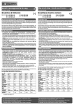
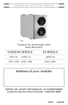
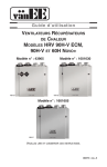
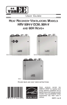
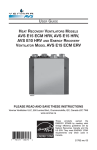
Installation and User Manual
VB0121
PRO225 & PRO250
HEAT RECOVERY VENTILATORS
READ AND SAVE THESE INSTRUCTIONS
Venmar Ventilation inc., 550 Lemire Blvd., Drummondville, QC, Canada J2C 7W9
www.venmar.ca
These products earned the
ENERGY STAR® by meeting strict
energy efficiency guidelines set by
Natural Resources Canada and the
US EPA. They meet ENERGY STAR
requirements only when used
in Canada.
08305 rev. B
!
WARNING
TO REDUCE THE RISK OF FIRE, ELECTRIC SHOCK, OR INJURY TO PERSON(S)
OBSERVE THE FOLLOWING:
1. These units are intented for residential installation only.
2. Use these units only in the manner intended by the manufacturer. If you have questions,
contact the manufacturer at the address or telephone number listed in the warranty.
3. Before servicing or cleaning the units, disconnect power cord from electrical outlet.
4. Installation must be done in accordance with all applicable codes and standards, including
fire-rated construction codes and standards.
5. These units are not designed to provide combustion and/or dilution air for fuel-burning
appliances.
6. When cutting or drilling into wall or ceiling, do not damage electrical wiring and other
hidden utilities.
7. Do not use these units with any solid-state speed control devices other than the Breeze
main control for the PRO250 unit exclusively or the 11136 main control for PRO225 unit.
The optional auxiliary control 20-minute lighted push button can be used with both
PRO250 and PRO225 units.
8. These units must be grounded. The power supply cord has a 3-prong grounding plug for
your personal safety. It must be plugged into a mating 3-prong grounding receptacle,
grounded in accordance with the national electrical code and local codes and
ordinances. Do not remove the ground prong. Do not use an extension cord.
9. Do not install in a cooking area or connect directly to any appliances.
10. Do not use to exhaust hazardous or explosive materials and vapors.
11. Do not run any air ducts directly above or closer than 2 ft (0.61 m) to any furnace or
its supply plenum, boiler, or other heat producing appliance.
12. When performing installation, servicing or cleaning of these units, it is recommended to
wear safety glasses and gloves.
13. When applicable local regulations comprises more restrictive installation and/or
certification requirements, the aforementioned requirements prevail on those of this
document and the installer agrees to conform to these at his own expenses.
CAUTION
1. To avoid premature clogged filters, turn OFF the unit during construction or renovation.
2. Please read specification label on product for further information and requirements.
3. Be sure to duct air outside – Do not intake or exhaust air into spaces within walls or
ceiling or into attics, crawl spaces, or garage.
4. Intended for residential installation only in accordance with the requirements of NFPA 90B.
5. The ductwork is intended to be installed in compliance with all applicable codes.
6. Do not use the PRO250 or PRO225 unit when varnishing. The varnish vapors may
damage these units.
7. At least once in a year, the unit mechanical and electronic parts should be inspected
by qualified service personnel.
8. During snow/rain storm, operate the PRO250 unit in recirculation mode to prevent water
build up in the heat recovery ventilator. Turn OFF the PRO225 unit.
2
TABLE OF CONTENTS
1. FUNCTIONS
OF YOUR
HEAT RECOVERY VENTILATOR..........................4
1.1 Air Exchange...............................................................................................4
1.2 Heat Recovery ............................................................................................4
1.3 Recirculation (PRO250 only).......................................................................4
2. DIAGRAMS OF AIRFLOWS ...............................................................5
3. DESCRIPTION OF THE UNIT .............................................................6
4. UNITS INSTALLATION ................................................................7-13
4.1 Installation Types with Required Installation Kit ..........................................7
4.2 Locating and Mounting the Unit ..................................................................8
4.3 Tools and Materials .....................................................................................8
4.4 How to Hang the Unit..................................................................................8
4.5 Planning of the Ductwork ............................................................................9
4.6 Installing Non-Insulated Flexible Ducts and Registers ..........................9-10
4.7 Connecting Insulated Flexible Ducts to the Unit Ports..............................11
4.8 Locating Exterior Ports..............................................................................12
4.9 Connecting Insulated Ducts to EXterior Ports ...........................................12
4.10 Connecting the Drain ................................................................................13
5. CONTROLS ............................................................................13-16
5.1 Integrated Control .....................................................................................13
5.2 Controls Connection to the Unit...........................................................14-15
5.3 Main Control Installation............................................................................16
6. OPERATING CONTROLS ..........................................................17-18
6.1 Breeze Main Control (PRO250 only) ........................................................17
6.2 11136 Main Control (PRO225 only)..........................................................18
6.3 20-minute Lighted Push Button Optional Auxiliary Control
(PRO250 & PRO225)..........................................................................................18
7. MAINTENANCE ............................................................................19
7.1 Regular Maintenance ................................................................................19
7.2 Annual Maintenance .................................................................................19
8. TROUBLESHOOTING .....................................................................20
Congratulations!
You have made an excellent choice!
The operating principle of your Heat Recovery Ventilator will protect your house and give
you personal comfort you have never known before.
We have prepared this Manual especially for you. Please read it carefully to ensure you
obtain full benefit from your Heat Recovery Ventilator unit.
Please take note this manual uses the following symbols to emphasize particular information:
0
! WARNING
Identifies an instruction which, if not followed, might cause serious
personal injuries including possibility of death.
CAUTION
Denotes an instruction which, if not followed, may severely damage the
unit and/or its components.
NOTE: Indicates supplementary information needed to fully complete an instruction.
We welcome any suggestions you may have concerning this manual and/or the unit, and we
would appreciate hearing your comments on ways to better serve you. Please forward all
correspondence to us at the address indicated on the product registration card included with
this manual.
3
1. FUNCTIONS OF YOUR HEAT RECOVERY VENTILATOR
Your PRO250 or PRO225 Heat Recovery Ventilator eliminates the excessive humidity
problems by exhausting stale and humid air to the outside and by drawing in fresh air. Either
unit offers superior air quality and fresh air sensation, an important factor to overall comfort,
by eliminating the accumulation of pollutants and humidity.
These units also come equipped with a heat recovery core which reduces ventilating costs
in winter.
The PRO250 and PRO225 Heat Recovery Ventilators are ventilation systems which carry
out the following operations:
1.1 AIR EXCHANGE (PRO250 & PRO225)
These units exhaust stale and humid air from the house and replace it with fresh air from
the outside.
1.2 HEAT RECOVERY (PRO250 & PRO225)
During winter, these units recover the heat contained in the stale air before it is exhausted,
and transfer it to the fresh air drawn from the outside (reverse process in summer).
Example (in winter):
STALE AIR FROM BUILDING
22°C/72°F
FRESH AIR FROM OUTSIDE
0°C/32°F
FRESH AIR TO BUILDING
18°C/64°F
STALE AIR TO OUTSIDE
4°C/39°F
VF0015
1.3 RECIRCULATION (PRO250
ONLY)
During the recirculation mode, this unit stops to exchange air with the exterior. Continuous
recirculation is thus undertaken inside the home and insures the purification of the ambient
air. Two mechanical filters trap the large dust particles (those visible to the eye).
4
2. DIAGRAMS OF AIRFLOWS
The direction of the airflows is indicated in each of the following diagrams. Please note that
the stale air never mixes with the fresh air.
STALE AIR
TO OUTSIDE
FRESH AIR
FROM OUTSIDE
STALE AIR
FROM BUILDING
FRESH AIR
TO BUILDING
DURING
AIR EXCHANGE
VF0045
STALE AIR
FROM BUILDING
DURING
DEFROST MODE
OR
RECIRCULATION
(PRO250 ONLY)
VF0046
5
FILTERED
AIR
TO BUILDING
3. DESCRIPTION OF THE UNIT
13
1
2
3
4
5
6
7
8
8
9
9
10
11
11
12
12
14
15
16
VL0035
1 Exhaust port:
2 Fresh air port:
3 Stale air intake port:
4 Distribution port:
5 Main damper:
6 Secondary damper:
7 Automatic defrost
unit :
8 Adjusting tools (2):
9 Mechanical filters (2):
10 Heat recovery core:
exhausts stale air to the outside, after the air has transferred its
heat inside the heat recovery core.
brings fresh air from the outside into the unit.
is connected to the registers located in the larger rooms of the
house.
distributes fresh air into the house, after it has absorbed the
heat of the stale air in the heat recovery core.
allows fresh air intake when open and defrost when closed.
allows stale air to exhaust when open and prevents negative
pressure when closed, in defrost mode.
consists of one damper actuator, dampers and related controls.
The defrost cycle is electronically controlled in response to the
outside temperature (-5°C [23°F] to -27°C [-17°F] or coldest)
and will increase in frequency as the temperature decreases.
Its duration is of 7 or 10 minutes.
adjust the dampers (one on each side) in balancing process.
Lock them in place once the unit is balanced.
trap the dust contained in the air and prevents the heat
recovery core from becoming obstructed.
is a crossflow type. It transfers the heat between the two air
streams.
11 Blowers (2):
draw fresh air from the outside and exhaust stale air to the outside.
12 Condensation tray:
is used to capture the water produced during heat transfer and
defrost (in cold climate).
for 120 V electrical supply.
contains capacitors (indispensable to proper motors operation)
and electronic control circuit (insures proper operation of the
unit).
located under the unit, allows to connect the controls.
is connected to the condensation tray and serves to drain the
water accumulation.
13 Electrical cord:
14 Electrical box:
15 Terminal connector:
16 Drainage tube:
6
4. UNIT INSTALLATION
4.1 INSTALLATION TYPES WITH REQUIRED INSTALLATION KIT
Here are the types of installation and installation kit needed depending on your house.
BUNGALOW
• LATERAL
• OPEN
BUNGALOW
• LATERAL OR CENTRAL STAIRWAY
• CLOSED-IN BASEMENT STAIRWELL
STAIRWAY
BASEMENT STAIRWELL
Basement installation kit no. CH30115.
Basement installation kit no. CH30115
with 3 or 4 floor registers (4” x 10”, not
included).
BUNGALOW
MULTI-LEVEL HOUSE
•4
• CENTRAL
LEVELS
• OPEN
STAIRWAY
BASEMENT STAIRWELL
Basement installation kit no. CH30115
with
additional
multi-level
kit
no. UT 2004.
Basement installation kit no CH30115
with
additional
multi-level
kit
no. UT 2004.
2-STORIED HOUSE
2-STORIED HOUSE
• OPEN
• CENTRAL STAIRWAY
• CLOSED-IN BASEMENT STAIRWELL
BASEMENT STAIRWELL
Basement installation kit no. CH30115
with one additional register (not included).
Basement installation kit no. CH30115
with 3 or 4 floor registers (4” x 10”, not
included).
7
4. UNIT INSTALLATION (CONT’D)
4.2 LOCATING
AND
MOUNTING THE UNIT
Choose
•
•
•
•
an appropriate location for the unit:
Within a heated area of the house (10 °C/50 °F or more)
Away from living areas (dining room, living room, bedrooms), if possible
So as to provide easy access for filter maintenance
Close to an exterior wall, so as to limit the length of the insulated flexible ducts to
and from the unit
• Close to a drain. (If no drain is close by, use a pail to collect run-off)
• Away from hot chimneys, electrical panel and other fire hazards
• Allow for a power source (standard 3-prong grounding outlet)
4.3 TOOLS
AND
MATERIALS
• Robertson no. 2 or
Phillips no. 2 screwdriver
• Cutter pliers
• Drill
• Jig saw
• Duct tape
• Caulking gun with a tube of silicone
sealant
• Metal shears (if the exterior covering is
aluminum or vinyl)
• Chisel and hammer (if the exterior covering
is brick)
4.4 HOW TO HANG THE UNIT
Use the 4 chains and springs (from the hardware pack included with the unit) to hang the
unit to ceiling joists.
CAUTION
Make sure the unit is level.
VD0204
8
4. UNIT INSTALLATION (CONT’D)
4.5 PLANNING
OF THE
DUCTWORK
• Keep it simple. Plan for a minimum of bends and joints. Keep the length of the
insulated ducts to a minimum.
• Do not use wall cavities as ducts. Do not use branch line smaller than 4” (102 mm)
diameter.
• Do not ventilate crawl spaces or cold room. Do not attempt to recover the exhaust
air from a dryer or a range hood; this will cause the clogging of the unit.
• Be sure to plan at least one exhaust register on the highest lived-in level of the
house, if it has 2 floors or more.
4.6 INSTALLING NON-INSULATED FLEXIBLE DUCTS
AND
REGISTERS
CAUTION
If ducts have to go through an unconditioned space, always use insulated
ducts (purchase separately).
4.6.1 STALE AIR EXHAUST DUCTWORK
0
! WARNING
Never install a stale air exhaust register in a room where a combustion
device operates, such as a gas water heater, a gas furnace or a fireplace.
• Install the stale air exhaust register(s) in the main area where the contaminants
are produced: kitchen, living room, etc. Position the register(s) as far from the
stairway as possible and in such a way that the air circulates in all the lived-in
spaces in the house.
• If a register is installed in the kitchen, it must be located at least 4 feet (1.2 m)
from the range.
• Install the register(s) 6 to 12 inches (152 to 305 mm) from the ceiling on an
interior wall OR install it in the ceiling.
4.6.2 FRESH AIR DISTRIBUTION DUCTWORK
• Install the fresh air distribution register(s) in a large, open area in the lowest
level to ensure the greatest possible air circulation. Keep in mind that the fresh
air register(s) must be located as far as possible from the stale air register(s).
• Install the register(s) in the ceiling OR 6 to 12 inches (152 to 305 mm) from the
ceiling on an interior wall. The duct length should be at least 15 feet (4.6 m).
(The cooler air will then cross the upper part of the room and mix with room air
before descending to occupant level.)
4.6.3 HOW TO CONNECT NON-INSULATED FLEXIBLE DUCTS TO THE REGISTERS
• Once the register location is determined,
cut out a 3¾” x 9¾” rectangular hole.
• Fix one end of the flexible duct to the register
transition (1), using a tie wrap and duct tape.
• From inside the wall (or ceiling), place the
transition opening flush to the finished wall.
• Assemble the register (2) to its transition
using its 2 no. 8 x 1½” screws.
See illustration beside.
9
1
VD0202
2
4. UNIT INSTALLATION (CONT’D)
4.6 INSTALLING NON-INSULATED FLEXIBLE DUCTS
4.6.4 CONNECTION TO
A. FRESH
A
AND
REGISTERS (CONT’D)
FORCED AIR SYSTEM
AIR TO BUILDING DUCT ONLY
0
! WARNING
When performing duct connections, always use approved tools and
materials. Respect all corresponding laws and safety regulations. Please
refer to your local building code.
• Cut an opening into the return duct not less
than 10 feet (3.1 m) from the furnace (A+B).
• Use a metal transition (not provided,
available in hardware stores) to connect the
fresh air to building duct to the furnace
return duct.
NOTE:For this type of installation, it is not
essential that the furnace blower runs
when the unit is in operation, but we
recommend it.
B. FRESH
A
METAL
TRANSITION
B
VJ0065
A+B = NOT LESS
THAN 10’ (3.1 M)
AIR TO BUILDING DUCT AND EXHAUST AIR FROM BUILDING DUCTS
0
! WARNING
When performing duct connections, always use approved tools and
materials. Respect all corresponding laws and safety regulations. Please
refer to your local building code.
CAUTION
For this type of installation, the furnace blower must be in operation when
the HRV is in operation.
Fresh air to building duct
• See point A above “Fresh air to building duct only”.
Exhaust air from building duct
• Cut an opening into
the return duct at
least at 3 feet (0.9 m)
from the fresh air
to building duct
METAL
connection to the
TRANSITION
return plenum.
• Use a metal transition
(not provided, available
in hardware stores) VJ0068
to connect the stale
air intake duct to the furnace return duct.
10
A
B
MINIMUM 3’
(0.9 M)
A+B = NOT LESS
THAN 10’ (3.1 M)
4. UNIT INSTALLATION (CONT’D)
4.6.5 HOW TO CONNECT NON-INSULATED FLEXIBLE DUCTS TO THE UNIT PORTS
• Each port is identified on top of the unit (see illustrations below). Attach the
fresh air to building duct and the exhaust air from building duct to their
corresponding port, using tie wraps (1).
Exhaust air from building
Aspiration d’air vicié
Fresh air to building
Distribution d’air frais
1
VO0148
VO0147
4.7
CONNECTING INSULATED FLEXIBLE DUCTS TO THE UNIT PORTS
CAUTION
Make sure the vapor barrier on the insulated ducts does not tear during
installation to avoid condensation within the ducts.
Use the following procedure for connecting the insulated flexible ducts to the unit ports
(exhaust to outside and fresh air from outside).
a) Pull back the insulation to expose the flexible duct.
b) Connect the interior flexible duct to the port using a tie wrap.
c) Pull the insulation over the joint and tuck it between the inner and outer ring
of the double collar.
d) Pull down the vapor barrier (shaded part in illustrations below) over the
outer ring to cover it completely. Fasten in place the vapor barrier using the
port strap (included in unit parts bag). To do so, insert one collar pin
through vapor barrier and first strap hole, then insert the other collar pin
through vapor barrier and center strap hole and close the loop by inserting
the first collar pin in the last strap hole.
Exhaust air to outside
Évacuation d’air vicié
a)
b)
c)
d)
Fresh air from outside
Aspiration d’air frais
COLLAR
COLLAR
PIN
VJ0060
11
PIN
4. UNIT INSTALLATION (CONT’D)
4.8 LOCATING EXTERIOR PORTS
Choose an appropriate location for installing the exterior ports:
• At a distance of at least 6 feet (1.8 m) one from the other
• At a minimum distance of 18 inches (457 mm) from the ground
! WARNING
Make sure the fresh air intake port is at least 6 feet (1.8 m) away (or more, as per
applicable building codes or standards) from sources of contamination such as:
• High efficiency furnace vent • Any exhaust from a combustion source
• Gas meter exhaust, gas barbecue-grill
• Garbage bin
STALE
AIR
EXHAUST
PORT
18’’
(457 MM)
6’
(1.8 M)
FRESH
AIR
INTAKE
PORT
6” Ø
(152 MM)
OPTIONAL
LOCATION
18’’
(457 MM)
6’
(1.8 M)
18’’ (457
MM)
VD0203
4.9 CONNECTING INSULATED DUCTS TO EXTERIOR PORTS
• For each exterior port,
using a jig saw, cut a 6’’
diameter hole in the
exterior wall.
• From the outside, slide the
exterior port in place and
attach it to the exterior
wall, using 2 no. 8 x 1½”
provided screws. Seal the
outline with silicone.
• From the inside, pull back
the insulation to expose
the flexible duct and, using
a tie wrap, attach it to the
exterior port rigid duct. VR0028
Carefully seal with duct
tape. Pull the insulation over the joint. Pull the vapor barrier over the insulation and
over the joint. Apply gently duct tape to the joint making an airtight seal. See above.
12
4. UNIT INSTALLATION (CONT’D)
4.10 CONNECTING THE
DRAIN
Cut 2 sections of the plastic tube, at least
16” (406 mm) long, and attach them to each inner
drain fitting, located under the unit. Join both
short sections to the “T” junction and main tube
as shown.
16"
(406 mm)
16"
(406 mm)
VO0154A
Make a water trap loop in the tube to prevent the
unit from drawing unpleasant odors from the drain
source. Make sure this loop is located OVER the
“T” as shown. Run the tube to the floor drain or to
an alternative drain pipe or pail.
TIE WRAP
IMPORTANT
If using a pail to collect water, locate the tube end
approximately 1” from top of th epail in order to
prevent watter from being drawn back up into the
unit.
± 1”
VD0232A
5. CONTROLS
5.1 INTEGRATED CONTROL
Those units are equipped with an integrated control, located under the unit, on the recessed
side of electrical compartment. Plug the unit. Use the push button (1) to control the unit. The
LED (2) will then show on which mode the unit is in.
SEE
PAGES
17 & 18
FOR UNIT OPERATION.
2
1
BOTTOM
VD0207
OF THE UNIT
Refer to table below to see how to operate the unit using its integrated control.
PRESS
PUSH BUTTON
ONCE
TWICE
THREE TIMES
ON
LED COLOR
AMBER
GREEN
NO LIGHT
13
RESULTS
UNIT IS ON LOW SPEED
UNIT IS ON HIGH SPEED
UNIT IS OFF
5. CONTROLS (CONT’D)
5.1 INTEGRATED CONTROL
(CONT’D)
If a problem occurs during the unit operation, its integrated control LED (2) will blink. The
color of the blinking light depends on the type of error detected. Refer to Section 8
Troubleshooting on page 20 for further details.
BOOT SEQUENCE
The unit boot sequence is similar to a personal computer boot sequence. Each times the unit
is plugged after being unplugged, or after a power failure, the unit will perform a 30-second
booting sequence before starting to operate. During the booting sequence, the integrated
control LED will light GREEN or AMBER for 5 seconds, and then will shut off for 2 seconds.
After that, the LED will light RED for the rest of the booting sequence. During this RED light
phase, the unit is checking and resetting the motorized damper position. Once the motorized
damper position completely set, the RED light turns off and the booting sequence is done.
NOTE: No command will be taken until the unit is fully booted.
5.2 CONTROLS CONNECTION TO THE UNIT
0
! WARNING
Always disconnect the unit before making any connections. Failure in
disconnecting power could result in electrical shock or damage of the
control or electronic module inside the unit.
Use the terminal connector included in the
installation kit to perform the electrical
connection for control. Check if all wires are
correctly inserted in their corresponding holes
in the terminal block. (A wire is correctly
inserted when its orange receptacle is lower
than another one without wire. On picture
beside, wire A is correctly inserted, but not
wire B.)
A
5.2.1 BREEZE MAIN CONTROL (PRO250
B
ONLY)
NO C NC I OC OL Y R G B
CO
M FO RT Z ON E
40
/ 2 00 7
VI
TE
SS
E
AUTO
03
2 60 V - 1
ER
UMM
É /S
ÉT
ÉCHANGE
AIR
EXCHANGE
MIN.
EXCÈS D’HUMIDITÉ
EXCESS HUMIDITY
RE-CIRC
MAX. PE ED
VE0180
14
5. CONTROLS (CONT’D)
5.2 CONTROLS CONNECTION TO THE UNIT
5.2.2 11136 MAIN CONTROL (PRO225
(CONT’D)
ONLY)
%HUM. RELATIVE HUM EXT. TEMPS.
80
0FF
70
60
50 5˚C+
55%
45%
35%
30%
°C EXT.
NO C NC I OC OL Y R G B
10 °
0°
-10 °
-20 °
40 -5˚C
30 -20˚C
20
25
-30˚C
% RELATIVE HUMIDITY
% HUMIDITÉ RELATIVE
VE0190
5.2.3 20-MINUTE LIGHTED PUSH BUTTON OPTIONAL
(PRO250 & PRO 225)
AUXILIARY
CONTROL
NO C NC I OC OL Y R G B
ON
VE0185
Once the control(s) connection has been made, insert the terminal connector under the unit,
on the recessed side of the electrical compartment.
TERMINAL
CONNECTOR
VD0207
15
5. CONTROLS (CONT’D)
5.3 MAIN CONTROLS INSTALLATION
For more convenience, the PRO250 and PRO225 units can also be controlled using the
included main controls: the Breeze main control for the PRO250 unit and the 11136 main
control for the PRO225 unit.
! WARNING
Always disconnect the unit before making any connections. Failure in
disconnecting power could result in electrical shock or damage of the
control or electronic module inside the unit.
0
CAUTION
The Breeze main control must be installed with the PRO250 unit only and
the 11136 main control with PRO225 unit.
CAUTION
Failure to comply with the following can cause erratic operation of the unit:
• Never install more than one control per unit.
• Keep control low voltage wiring at least 1 foot (305 mm) away from
motors, lightning ballast, light dimming circuit and power distribution
panel. Do not route control wiring alongside electrical wires.
• Ensure the wires are securely connected.
• Disconnect power from the unit before removing the control faceplate
from its mounting plate.
1. Route the cable from the unit to a convenient location for the control.
2. Remove the button and the cover plate of the control (see figure
beside). If necessary, bore the mounting holes and insert anchors.
VC0110
3. Pass the cable (4 wires) through the opening of the mounting plate and mount the plate
to the wall using the provided screws.
5. Reinstall cover plate and button.
Y
6. Plug the unit.
16
R
GB
VE0124
4. Splice back the end of the cable to access to the 4 wires.
Strip the end of each wire. Connect each wire to its
corresponding terminal: YELLOW wire to “Y’’, RED wire
to “R’’, GREEN to “G’’ and BLACK to “B’’. See illustration
beside.
6. OPERATING CONTROLS
6.1 BREEZE MAIN CONTROL (PRO250
ONLY)
NOTE: The integrated control must be turned OFF to use this control.
AIR EXCHANGE
INDICATOR
VI
TE
SS
E
EXCESS HUMIDITY
INDICATOR
/200 7
40
03
2 60 V - 1
AUTO
CO
M FORT Z ON E
É
ÉT
HUMIDITY
CONTROL KNOB
AUTOMATIC
MODE INDICATOR
MMER
/ SU
ÉCHANGE
AIR
EXCHANGE
MIN.
EXCÈS D’HUMIDITÉ
EXCESS HUMIDITY
RE-CIRC
MINIMUM SPEED
INDICATOR
MAX. SPEED
RECIRCULATION
INDICATOR
PUSH BUTTON
VC0109
ADJUSTING AIR SUPPLY CONTROL
1) Select “RE-CIRC”, “MIN.” or “AUTO” using the push button.
• When “RE-CIRC” is selected, the recirculation indicator lights up. If the humidity control
knob is set to the left of the “click”, the unit will recirculate air on high speed and if it is
set to the right of the “click”, the unit will exchange air, on high speed, with the outside
until the desired humidity level has been reached. During this time, the excess humidity
and air exchange indicators will be lit.
• When “MIN.” is selected, the minimum speed and air exchange indicators light-up. If the
humidity control knob is set to the left of the “click”, the unit will exchange in low speed
with the outside and if it is set to the right of the “click”, the unit will exchange air, on
high speed, with the outside until the desired humidity level has been reached. During
this time, the excess humidity indicator will be lit.
• When “AUTO” is selected, the automatic indicator lights-up. If the humidity control knob
is set to the left of the “click”, the unit will turn OFF for the first 40 minutes and operate
on air exchange mode with the outside, in low speed, during the last 20 minutes of the
hour. The air exchange indicator will be lit. If the humidity control knob is set to the right
of the “click”, the unit will exchange air, on high speed, with the outside until the desired
humidity level has been reached. During this time, the excess humidity indicator will be lit.
2) To turn off the unit, press on the push button once again.
ADJUSTING HUMIDITY CONTROL
SETTING DURING THE SUMMER MONTHS:
During this period, unless being afflicted with breathing problems, using the humidity control
is unnecessary; set the unit in recirculation mode. (Do not exchange in day time; exchange
at night time if cool outside or if it’s not raining.)
SETTING DURING THE FALL, WINTER AND SPRING MONTHS (CONDENSATION APPEARS ON WINDOWS):
1) Determine the humidity level in your house (bring the knob counterclockwise to its
maximum position, then bring it back clockwise slowly until you hear a “click”).
2) Set the knob to one line under this temperature level or “click”.
CAUTION
Do not set a temperature below -20°C (-4°F). This could lead to excessive
dryness in the air causing discomfort for the occupants.
It is possible (and normal) to experience condensation on your windows when drastic
changes in temperature happen (for example: -5°C [23°F] to -20°C [-4°F]). In that case,
we suggest waiting a few days to allow the situation to stabilize.
17
6. OPERATING CONTROLS (CONT’D)
6.2 11136 MAIN CONTROL (PRO225
ONLY)
NOTE: The integrated control can be turned OFF (no light) or at Minimum speed (amber led)
to use this control.
HUMIDITY LEVEL SELECTOR
USING THE HUMIDITY LEVEL SELECTOR:
Winter: (outside temperature between 5°C and -30°C)
– Position the selector between 50% and 25%,
pointing approximately to the corresponding
55%
10 °
70 60
80
45%
0°
0FF
outside temperature.
35%
-10 °
50 5˚C+
30%
-20 °
40
-5˚C
– If there is condensation or frost on the windows,
30 -20˚C
20
then lower the humidity level by 1% to 2% every
25
24 hours until the condensation has evaporated.
-30˚C
– Do not go lower than 25%: the air will become too
dry for human comfort.
Spring and Fall:
– Position the selector anywhere between 75% and
50% (higher on warm days, lower on cold days).
– If certain periods during the spring and fall seem VC0022
more like winter, follow the instructions given for humidity control during the winter.
Summer:
– Position the selector at 80% during the day.
– Lower the selector to 20% to introduce cool fresh air into the house during certain
summer nights.
%HUM. RELATIVE HUM EXT. TEMPS.
°C EXT.
% RELATIVE HUMIDITY
% HUMIDITÉ RELATIVE
IMPORTANT EXPLANATIONS ABOUT HUMIDITY LEVELS:
The comfort level for human beings is between 30% and 45% relative humidity. To measure
the present humidity level in your house, proceed as follows:
– Turn the dial to 80%.
– Turn the dial slowly clockwise until you hear a “click”. The dial will then be pointing to
the value for the present humidity level (precision of 5%).
Turn the selector to the right of the “click” to lower the humidity level in the house. This will
initiate the «air exchange» mode on your ventilation system and replace the stale humid air
from inside with dryer air from outside. Avoid to try to lower the humidity with «air exchange»
on rainy or foggy days.
Turn the selector to the left of the “click” to cancel «air exchange» mode.
NOTE: The above instructions are guidelines. According to home insulation, type of windows
or to meet specific needs, different values can be selected to achieve comfort.
6.3 20-MINUTE LIGHTED PUSH BUTTON OPTIONAL AUXILIARY CONTROL
(PRO250 & PRO225)
Location: Located in the bathroom or in other locations where there
is temporary humidity excess or pollutants.
Purpose: To eliminate excess humidity produced by showers or other
periodic activities producing pollutants.
NOTE: This control is sold separately.
Press once to activate the push-button.
The unit will operate on high speed for 20 minutes and the indicator will
light up. To stop activation before the end of the 20-minute cycle, push
one more time.
The unit will get back to its previous setting.
ON
VC0082
18
7. MAINTENANCE
0
! WARNING
Dangerous voltage may be present. During maintenance and repairs, the
unit must always be turned off, then unplugged. We take great care to
minimize sharp edges; however, please proceed with caution when handling
all components. When cleaning the unit, it is recommended to wear safety
glasses and gloves.
7.1 REGULAR MAINTENANCE
1.
2.
The motors are factory lubricated for life. Lubricating the bearings is not recommended.
The heat recovery core must be handled with care. We recommend that it be washed
once a year, following the season of most intense use, in order to insure maximum
efficiency of the plastic partitions. Allow the heat recovery core to soak for 3 hours in
a solution of warm water and mild soap. Rinse under a stream of water.
CAUTION
Hot water and a strong detergent will damage the heat recovery core.
3.
4.
The air filters are washable. Under normal conditions, we recommend that they be
washed every 3 months.
Use vacuum cleaner to remove the heaviest portion of accumulated dust, then wash
in hot water.
Regularly check the exterior fresh air intake port and clean when necessary. Also
check during very cold weather because ice may grow on the screen located at the
exterior intake hood.
7.2 ANNUAL MAINTENANCE
NOTE: Ask your installer for an annual service contract.
Annual service should include:
1) Cleaning filters, heat recovery core and the exterior air intake/exhaust ports.
2) Cleaning the wheels and the blowers blades.
3) Cleaning the condensation tray with soapy water (make sure that the drain is not
clogged).
4) Running the system and checking the different operating modes.
19
8. TROUBLESHOOTING
If you think your unit is malfunctioning, check some of the followings:
PROBLEMS
TRY THIS...
1.
The LED of the
integrated control is
blinking red.
• There is a problem with the exhaust motor. The unit is
OFF. Contact your installer.
2.
The LED of the
integrated control is
blinking green.
• There is a problem with the thermistor. The unit is still
working, but will defrost frequently. Contact your installer.
3.
The LED of the
integrated control
is blinking amber.
• There is a problem with the motorized damper. The unit is
OFF. For a 2½-hour period, the unit will try to reset the
damper at every 30 minutes. After 2½ hours, if the
problem is not solved, the unit stops trying to reset
damper.
• Contact your installer.
• Check control wiring.
4.
The integrated control
push button does not
work.
Nothing works.
• The 30-second boot sequence is not completed. See
Booting Sequence on page 14.
6.
Condensation
on windows.
(Air too humid.)
• Adjust the humidity control knob as per instructions (see
Section 6).
• Leave curtains half-open to allow air circulation.
• Store all firewood in a close room with a dehumidifier or
in a well ventilated room, or store the wood outside.
• Keep the temperature in your house above 18°C (64°F).
• Set the unit at high speed during activities generating
excess humidity (family gatherings, extra cooking, etc.).
7.
Air too dry.
• Temporarily use a humidifier.
• Using integrated control, set the unit at low speed.
• PRO250 unit only (with Breeze control)
- Do not adjust your humidity control below -20°C (-4°F).
- Set the unit at minimum speed (MIN.).
- Temporarily switch to the AUTOMATIC mode.
• PRO225 unit only (with 11136 control)
- Set the Humidity level selector below 30% (see 6.2 on
page 18).
8.
Air too cold at the air
supply grille.
•
•
•
•
•
5.
• See if the unit is plugged in.
• See if the unit is receiving power from the house circuit
breaker or fuse.
Make sure the outside ports are not blocked.
Have the unit defrost system checked.
Install a duct heater.
Using integrated control, set the unit at low speed.
PRO250 unit only (with Breeze control)
- Set the unit at minimum speed (MIN.).
20