1
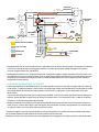
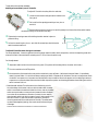
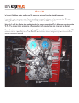
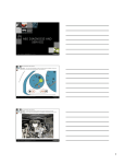
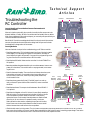
Te c h n i c a l S u p p o r t
Articles
Troubleshooting the
RC Controller
Hour Dial
Fuse
Auto/Off Switch
Learn to Identify and Correct the Most Common Electromechanical
Controller Problems
When an irrigation system fails, the controller is usually the first component to be
blamed. However, in reality, 30-50% of controllers returned actually have no defects.
With a few troubleshooting tips and techniques, you can easily save yourself and your
customer valuable time and money.
Rain Bird’s RC Controllers are designed with basic functions that minimize maintenance and provide solutions as simple as the design itself. All you need is a basic
knowledge of AC voltage and a volt-ohmmeter.
Day Dial
Covering the Basics
Station Dial
Wafer Switch
Here are a few basic checkpoints for troubleshooting your RC Series controller.
• Check the programming. This includes the start time (time of day that irrigation
should begin), run time (length of irrigation for each station) and days on
(actual days the irrigation will operate). If any part of the programming is missing, the controller will not activate some or all of the valves.
• Check the Auto/Off switch. Make sure the controller is in the AUTOMATIC or
ON position.
• Determine whether the system has either rain or moisture sensors. A sensor cuts
power off to the valves. The controller will run as programmed, but no watering will occur.
• Check for the correct time/day. The controller should always show the correct
time and day as long as it is connected to the primary power source. If
the time or day is not correct, check the primary power, transformer,
circuit breaker or fuse.
• Check the primary power. Verify that 117 volt VAC power is on and correctly connected. If power is above 129 or below 105, contact a certified
electrician.
Hour
Dial Shaft
Assembly
Station
Dial Shaft
Assembly
Timing
Motor
Resistor
Pivot
Shaft
Assembly
Microswitch-Day
Timing
Motor
Rapid
Advance
Motor
• Check the transformer. The output should be between 24 and 28 VAC. If
not, replace it.
• Check the circuit breaker or fuse. If it is blown, it’s most likely caused by a
field wiring short. The electromechanical controller will stop on the station that caused the problem. Reset the controller in rest position,
replace the fuse or circuit breaker. Manually advance to station #1 and
allow it to run for one minute. If it operates correctly, continue to
Station #2 and the other stations, repeating the process until the fuse
blows. Disconnect the wire that operates that valve. Be sure to test all
stations because there could be more than one problem.
Reduction
Gear Shaft
Assembly
Microswitch-Hour
Auto/Off
Switch
MicroswitchStation Dial
Fuse
Holder
• Check the clock motor (or timing motor). The clock motor must operate continuously whether the controller is on or off, in order to
keep proper time; therefore, this motor may fail after an extended time. Verify that the motor is receiving proper voltage. Then set the
hour to the correct time and wait one hour. If the hour dial has not moved, replace the motor.
YEL
YEL
GRAY
WHT/BLU
E2
BLK OR YEL
STATION DIAL
MICROSWITCH
WIRE NUT
WHT/GRY
GRAY
WHT/BLU
B4
8
7
BC6
HOUR
DIAL
WAFER SWITCH – BACK
B2
BC3
COM
WHT
WHT
RED
1
2
DAY
DIAL
BRN
DAY DIAL
MICROSWITCH
3
4
E3
WIRE NUT
AUTO/OFF
ORN
RED
BRN
WHT/ORN
WHT/BRN
TIMING
MOTOR
BLK
F1
WHT/BRN
YEL
M2
STATION
DIAL
WAFER SWITCH
– FRONT
RED
RAPID ADVANCE
MOTOR
REST
BLK OR YEL
REST
POSITION
HOUR DIAL
MICROSWITCH
WHT/GRN
BRN
M1
FUSE
BLK
OR YEL
B5
43 ohm/5w
RESISTOR
C
WHT/RED
WHT/RED
NEUTRAL AND VALVE COMMON
J1
P1
4
4
3 2 1 9 10 11
3 2 1 9 10 11
24 VAC TO STATION
HOT/24 VAC
ORN
RED
BRN
WHT/ORN
YEL
MASTER VALVE
WHT
WHT/BRN
TO VALVES
STATION 1
WHT/RED
VALVE
COMMON
ORN
B1 24 VAC
TRANSFORMER
LINE VOLTAGE
ORN
MASTER
VALVE
• Change the resistor. Each RC Controller has a 43 ohm, 5-watt resistor, wired in-series to the timing motor. The purpose of this resistor is
to limit current and reduce heat in the timing motor. Without it, the motor will not last long. When changing the timing motor,
you must change the resistor also. (Part #651137)
• Test the gears and clutches. The RC-Series electromechanical controllers all use gears to transfer the rotation of the clock motor to the
hour and station timing. If you suspect a problem, try to very gently rotate the station dial and hour dial on the face plate in the opposite direction from the direction that the arrows show. If it rotates backwards without much force, the gear and clutch assembly is
stripped and it’s time to replace it.
DO NOT EXERT EXCESSIVE FORCE FOR THIS TEST.
• Check the advance motor (or rapid advance motor). This motor operates only when the controller is changing stations or returning
to rest position. To determine whether or not the motor is receiving proper voltage, check the leads with a volt-ohmmeter for 24 VAC.
By turning all stations off and manually rotating the station dial to the OFF or rest position, you can apply power to the rapid
advance motor.
If you do not have voltage at the leads, the micro switch may have failed. Check the micro switch (see section below for testing micro
switches). Another good test is to apply 24 volt AC directly from another source. If the motor does not turn, it needs to be replaced.
If it does turn, check the primary power and transformer.
• Test the micro switches. Your controller’s micro switches are small switches that, when activated, instruct the controller to perform a
certain function. If a micro switch fails or is out of adjustment, the controller will not perform as programmed. Your controller relies
on a day micro switch, hour micro switch and timing dial micro switch.
To determine whether or not a micro switch has failed, turn off primary power to the controller and conduct a resistance test using a
volt-ohmmeter. Resistance should be below 2 ohms when closed and infinite when open.
Remember, the button of the micro switch should not be depressed until the program pin is locked into position to activate the switch.
To adjust the micro switches, see below.
Adjusting micro switches in your RC Controller
To adjust RC Controller hour/day dial micro switches:
1. Loosen the two screws holding the switch bracket to the
front panel.
2. Pull out all but four equally spaced day or hour pins on
each dial.
3.
Set each switch bracket so the four pins remaining barely touch the surface of the switch breaker
arm before coming into contact with the ramp.
4. Tighten both mounting screws while holding the switch bracket in place to
prevent shifting.
5. Pull out the remaining four pins on
each dial. All retracted pins should clear the
1/32"
switch bracket actuator arm.
To adjust RC Controller station timing micro switches:
For course adjustment - loosen the righthand mounting screw, rotate the station dial to rest position, and turn the adjusting screw clockwise until the back of the metal switch actuating arm is 1/32-inch from the switch body.
For fine adjustment:
1. Adjust each station knob to the minimum timing mark. (The pointer will not always fall on the center at this mark.)
2. Turn the controller to the AUTO position.
3. Move the station dial clockwise from rest position and allow it to stop at Station 1. After the dial stops at Station 1, immediately
rotate it just past Station 1. It should now advance and stop at Station 2. Repeat this for all stations. Now, turn the adjustment screw
clockwise in one quarter-turn increments until the dial fails to stop at a station. When that happens, turn the adjusting screw back
a quarter-turn counterclockwise. Make sure that the dial stops at every station and that the gap between the actuating arm and the
switch is at least 1/64-inch.
• Check the wafer switches. The wafer switch is the distribution point for
the valve voltage. As the center hub turns with the station dial, the wafer
switch is connected to the station dial shaft. As it turns, a tab on the wafer
switch touches the station contact point and powers the valve. Problems
occur when dirt accumulates on the tabs or contacts. You can carefully
clean the wafer switch hub with the eraser of a pencil, being careful not to
bend the contacts. To clean the back side of the switch, remove the
mounting screws and lift the wafer switch off its shaft. The wafer switch
can also be damaged by lightning. Burn marks would indicate this type
of damage.
Notice on the front wafer switch that the tab is in contact with Station #1.