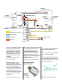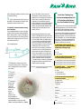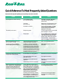
1
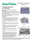
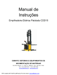
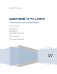
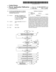
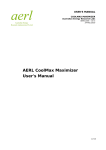
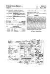
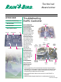
Te c h n i c a l
Newsletter
Special Issue
Published by Rain Bird Sales, Inc. Turf Products
Fall 1999
Troubleshooting
the RC Controller
IN THIS ISSUE:
RC Controller Troubleshooting
5000 Series Rotor
Online Irrigation Answers
Hour Dial
Auto/Off Switch
Day Dial
Wafer Switch
Learn to Identify and
Correct the Most Common
Electromechanical
Controller Problems
Rain Bird Contest
Fuse
Station Dial
When an irrigation system
fails, the controller is usually the first component to
be blamed. However, in
reality, 30-50% of controllers returned actually
have no defects. With a
few troubleshooting tips
and techniques, you can
easily save yourself and
your customer valuable time and money.
Rain Bird’s RC
Controllers are
designed with basic
functions that minimize maintenance and
provide solutions as
simple as the design
itself. All you need is a
basic knowledge of AC
voltage and a voltohmmeter.
Covering the Basics
Here are a few basic
checkpoints for troubleshooting your RC
Series controller.
Station
Dial Shaft
Assembly
Hour
Dial Shaft
Assembly
Reduction
Gear Shaft
Assembly
Timing
Motor
Resistor
Pivot
Shaft
Assembly
Microswitch-Day
Timing
Motor
Microswitch-Hour
Rapid
Advance
Motor
MicroswitchStation Dial
Auto/Off
Switch
Fuse
Holder
• Check the programming. This includes the start time (time of day that irrigation
should begin), run time (length of irrigation for each station) and days on (actual
days the irrigation will operate). If any part of the programming is missing, the
controller will not activate some or all of the valves.
• Check the Auto/Off switch. Make sure the controller is in the AUTOMATIC or
ON position.
• Determine whether the system has either rain or moisture sensors. A sensor cuts
continued on next page
[
Editorial
by Rod Waller
]
Can you troubleshoot a Rain Bird RCSeries Controller? How skilled are you at
repair? We devoted this issue of the
Technical Newsletter to electromechanical controllers to challenge and inform
you. Plus, if you are a Rain Bird
Authorized Service Center (ASC), Level 2
or higher, you are asked to repair these
units to maintain your ASC status.
As a reminder, here is an excerpt from
the 1999 ASC Program Guide:
• Level 2 - “Perform repairs on-site or
within your inter-branch system on
75% of all electromechanical controllers.”
• Levels 3 & 4 – “Perform repairs on-site
or within your inter-branch system,
rather than sending them to outside
vendors, on 90% of all electromechanical and solid-state controllers.”
If you are having trouble meeting these
requirements, please let us know how
we can help. Your success is important
to Rain Bird.
An RC-Series Controller can be tested
in five minutes at the counter. Fifty
percent of the problems can be caught
right there. For example, if the controller tests OK, the trouble may be in
the field wiring or primary power supply. Identifying this quickly saves the
contractor time in the field. Testing
may yield some important clues,
enabling a more rapid field diagnosis.
By the way, Rain Bird receives numerous inquiries regarding Year 2000 compliance for RC-Series controllers. I’m
not kidding. Call it a hunch, but I think
they’ll work just fine.
Rod Waller
Authorized Service Center Manager
520.434.6259
[email protected]
Rain Bird Sales, Inc. • 6640 South
Bonney Ave. • Tucson, AZ 85706
continued from front
power off to the valves. The controller
will run as programmed, but no watering will occur.
• Check for the correct time/day. The
controller should always show the
correct time and day as long as it is connected to the primary power source. If
the time or day is not correct, check the
primary power, transformer, circuit
breaker or fuse.
• Check the primary power. Verify that 117
volt VAC power is on and correctly connected. If power is above 129 or below
105, contact a certified electrician.
• Check the transformer. The output
should be between 24 and 28 VAC. If not,
replace it.
• Check the circuit breaker or fuse.
If it is blown, it’s most
likely caused by
a field wiring
short. The
electromechani-
Timing Motor
(above)
Resistor
(below)
one problem.
• Check the clock motor (or timing motor).
The clock motor must operate continuously whether the controller is on or off,
in order to keep proper time; therefore,
this motor may fail after an extended
time. Verify that the motor is receiving
proper voltage. Then set the hour to the
correct time and wait one hour. If the
hour dial has not moved, replace the
motor.
• Change the resistor. Each RC Controller
has a 43 ohm, 5-watt resistor, wired inseries to the timing motor. The purpose
of this resistor is to limit current and
reduce heat in the timing motor.
Without it, the motor will not last long.
When changing the timing motor,
you must change the resistor also.
(Part #651137)
• Test the gears and clutches. The RC-Series
electromechanical controllers all use
gears to transfer the rotation of the clock
motor to the hour and station timing. If
you suspect a problem, try to very gently
rotate the station dial and hour dial on
the face plate in the opposite direction
from the direction that the arrows show.
If it rotates backwards without much
force, the gear and clutch assembly is
stripped and it’s time to replace it.
DO NOT EXERT EXCESSIVE FORCE
FOR THIS TEST.
cal controller will stop on the station
that caused the problem. Reset the controller in rest position, replace the fuse
or circuit breaker. Manually advance to
station #1 and allow it to run for one
minute. If it operates correctly, continue
to Station #2 and the other stations,
repeating the process until the fuse
blows. Disconnect the wire that operates
that valve. Be sure to test all stations
because there could be more than
• Check the advance motor (or rapid
advance motor). This motor operates
only when the controller is changing
stations or returning to rest position. To
determine whether or not the motor is
receiving proper voltage, check the leads
with a volt-ohmmeter for 24 VAC. By
turning all stations off and manually
rotating the station dial to the OFF or
rest position, you can apply power to the
rapid advance motor.
YEL
YEL
GRAY
WHT/BLU
E2
BLK OR YEL
STATION DIAL
MICROSWITCH
WIRE NUT
WHT/GRY
GRAY
WHT/BLU
B4
8
7
BC6
HOUR
DIAL
WAFER SWITCH – BACK
B2
BC3
COM
WHT
WHT
RED
1
2
DAY
DIAL
BRN
DAY DIAL
MICROSWITCH
3
4
E3
WIRE NUT
AUTO/OFF
ORN
RED
BRN
WHT/ORN
WHT/BRN
TIMING
MOTOR
BLK
F1
WHT/BRN
YEL
M2
STATION
DIAL
WAFER SWITCH
– FRONT
RED
RAPID ADVANCE
MOTOR
REST
BLK OR YEL
REST
POSITION
HOUR DIAL
MICROSWITCH
WHT/GRN
BRN
M1
FUSE
BLK
OR YEL
B5
43 ohm/5w
RESISTOR
C
WHT/RED
WHT/RED
NEUTRAL AND VALVE COMMON
J1
P1
4
4
3 2 1 9 10 11
3 2 1 9 10 11
24 VAC TO STATION
HOT/24 VAC
ORN
RED
BRN
WHT/ORN
YEL
MASTER VALVE
WHT
STATION 1
If you do not have voltage at the leads,
the micro switch may have failed.
Check the micro switch (see section
below for testing micro switches).
Another good test is to apply 24 volt
AC directly from another source. If
the motor does not turn, it needs to
be replaced.
If it does turn, check the primary
power and transformer.
• Test the micro switches. Your controller’s micro switches are small
switches that, when activated, instruct
the controller to perform a certain
function. If a micro switch fails or is
out of adjustment, the controller will
not perform as programmed. Your
controller relies on a day micro switch,
hour micro switch and timing dial
micro switch.
To determine whether or not a micro
WHT/RED
WHT/BRN
TO VALVES
VALVE
COMMON
ORN
B1 24 VAC
TRANSFORMER
LINE VOLTAGE
ORN
MASTER
VALVE
switch has failed, turn off primary power
to the controller and conduct a resistance test using a volt-ohmmeter.
Resistance should be below 2 ohms
when closed and infinite when open.
Remember, the button of the micro
switch should not be depressed until the
program pin is locked into position to
activate the switch.
To adjust the micro switches, see below.
1.
Loosen the two screws holding the
switch bracket to the front panel.
2.
Pull out all but four equally spaced
day or hour pins on each dial.
3.
Set each switch bracket so the four
pins remaining barely touch the surface
of the switch breaker arm before coming
into contact with the ramp.
Adjusting micro switches
in your RC Controller
To adjust RC
Controller
hour/day dial
micro switches:
4. Tighten both mounting screws
while holding the switch bracket in place
to prevent shifting.
5.
Pull out the remaining four pins on
each dial. All retracted pins should clear
the switch bracket actuator arm.
To adjust RC Controller station timing
micro switches:
For course adjustment - loosen the righthand mounting screw, rotate the station
dial to rest position, and turn the adjusting screw clockwise until the back of the
metal switch actuating arm is 1/32-inch
from the switch body.
For fine adjustment:
1/32"
1. Adjust each station knob to the
minimum timing mark. (The pointer
will not always fall on the center at
this mark.)
2. Turn the
this for all stations. Now, turn the
adjustment screw clockwise in one
quarter-turn increments until the dial
fails to stop at a station. When that
happens, turn the adjusting screw
back a quarter-turn counterclockwise.
Make sure that the dial stops at every
station and that the gap between the
actuating arm and the switch is at
least 1/64-inch.
• Check the wafer switches. The wafer
switch is the distribution point for the
valve voltage. As the center hub turns
with the station dial, the wafer switch
is connected to the station dial shaft.
As it turns, a tab on the wafer switch
touches the station contact point and
powers the valve. Problems occur
when dirt accumulates on the tabs or
contacts. You can carefully clean the
wafer switch hub with the eraser of a
pencil, being careful not to bend the
contacts. To clean the back side of the
switch, remove the mounting screws
and lift the wafer switch off its shaft.
The wafer switch can also be damaged
by lightning. Burn marks would indicate this type of damage.
Notice on the front wafer switch that the tab is
in contact with Station #1.
[
Put On Your Thinking Cap...
RC Controllers to the Test and
Earn Your Free Rain Bird Cap!
Try your hand at correctly answering the
following questions. If you are one of the
first 100 to submit the right answers,
you will receive a FREE Rain Bird hat.
Choose one of the following answers for
each. Circle your answers on the form
below and submit it to Rain Bird by fax
520-434-6289 or by e-mail [email protected]. The correct answers will be
published in the next issue. Allow 4-6
weeks for delivery of your hat.
1.The 24-hour clock on the RC controllers allows you to select how many
different start times per day?
a. 1-24
b. 1-23
c. any number
2.With 12-station RC controllers, you
can set the watering times from ______.
a. 3-60 minutes in one-minute increments
b. 6-60 minutes in two-minute increments.
c. 6-60 minutes in one-minute increments.
3. The RC-C uses a ____ to protect the
system against short circuits.
a. fuse
b. circuit breaker
controller to
the AUTO
position.
c. quick release plug
3. Move the
a. station dial
station dial
clockwise
from rest
position and
allow it to
stop at
Station 1.
After the dial
stops at Station 1,
immediately rotate it
just past Station 1. It should now
advance and stop at Station 2. Repeat
]
Put Your Knowledge of Rain Bird
4. The RC controllers can be started
manually using the ______.
b. MODE switch
c. day dial
Name: ___________________________________
Company:________________________________
Address:__________________________________
City:____________State: _______ Zip: ________
Phone: ___________________________________
FAX: _____________________________________
E-mail address: ___________________________
Quick Reference To Most Frequently Asked Questions
Here are solutions to specific problems you’re most likely to encounter in the field:
Problem
Clock stopped. Hour dial not turning.
Cause
Circuit breaker tripped
(RC-C and RC-AB models only)
Fuse blown
(RC-Bi models only)
Time of day is not correct.
Solution
Push reset. If controller stops again,
check field wiring for possible
short circuits.
Replace fuse. If fuse blows again, check
field wiring for possible short circuit.
No power to controller
Check transformer power. If voltage
is zero, check line voltage and check
primary power. If zero, check the
building’s circuit breaker.
Faulty timing motor
To check, reset the time on the hour dial
and check back in one hour.
Faulty resistor
Or try a resistance test. The test should
show about 300 ohms for a good clock
motor without the resister on it. With
resistor in place, add another 43 ohms.
Check the resistor - it should read 43
ohms. If not, replace it with Part #651137.
Clock stops between Station 4 and
REST on any RC-4 model.
There is a factory built-in 20-minute
delay on four-station controllers.
None - this is a standard feature.
Controller recycles immediately
without stopping in the rest position.
Insufficient cycle time was allowed.
Adjust total run time for more than
20 minutes
Day and hour dials function correctly,
but cycle will not start correctly.
Off-auto switch is in wrong position.
Move switch to the AUTO or ON position.
Pins on day and hour dial not programmed correctly.
Re-program as necessary.
Day and hour micro switches out of
adjustment
See section on micro switch adjustments above.
Defective day or hour micro switches.
Test with volt-ohmmeter and replace
as needed.
The RC-AB Series controllers have a
three-position “day” switch. When the
switch is all the way out, it is off. When
the switch is half-way in, it operates program A or the upper panel stations only.
When the switch is all the way in, it
operates both the A and B programs
(upper and lower panel stations).
To correct, ensure the switch is pushed
in to the appropriate position.
The lower panel must begin operation
before midnight on the watering day if
the following day is scheduled as an
“off” day. Another option is to install a
6 a.m. change-over hour dial.
Ensure start time is programmed so
the lower panel cycle begins before
midnight.
Stations controlled by the top panel (on
the RC-1860AB or RC-2360AB) operate
correctly during an automatic cycle
schedule, but the set of stations controlled by the lower panel do not water.
(It takes about 20 minutes for the hour dial pin
to sweep past the micro switch. This allows the
hour dial start pin to move off the micro switch.
The micro switch must be open or it will allow
another start. In other words, if the total time on
all stations is less than 20 minutes, the controller
will go past the final station, advance to rest and
immediately initiate another cycle start.)
[
Put Performance
Over the Top With New
5000 Series Rotors
]
Durability, performance and the
convenience of arc adjustment
from the top. These are a few of
the benefits you’ll find in the
rugged, mid-range 5000 Series
Rotor, the newest addition to
Rain Bird’s residential and light
commercial line.
The unique 5000 Series Rotor
offers easy adjustment to the arc
from the top with no special tools
-only a flat-head screwdriver. The
arc can be adjusted from 40 to 360 degrees.
This versatile rotor also offers the convenience of reversing full- or part-circle
operation in one product, said product
manager J. R Bergantino. A non-reversing,
full-circle-only model is also available.
The rotor uses a proven water-lubricated,
gear-driven design and offers a unique
reinforced flow path for additional
side-load strength, explained Bergantino.
It also provides special O-ring seals for
better performance in gritty water. The
new 5000 Series Rotor is available in four,
six or 12-inch models with a TREE of six
low angle nozzles with a 10% trajectory
angle, three Radius + nozzles for a throw
of 29 to 50 feet, and six standard Rain
Curtain nozzles with a trajectory of 25%
and a throw from 23 to 40 feet. Customers
can also choose either a 2.0 or 3.0 GPM
pre-installed Rain Curtain nozzle.
A pressure-activated, multi-function wiper
seal blocks debris from the rotor’s internal
parts to ensure pop-up and retraction. In
addition, a heavy-duty retract spring
ensures positive pop-down.
A durable rubber cover is standard. The
rotor also offers fast forward arc check and
optional Seal-A-Matic (SAM) check valves
to prevent low head drainage in elevations
up to seven feet.
Backed by Rain Bird’s five-year warranty,
the new 5000 Series Rotor delivers reliable
performance from the top down.
Online Irrigation Answers
on the World Wide Web
Have You Connected With Rain Bird?
The latest Rain Bird products and
changes. Technical tips. Answers to
some of the most frequently asked irrigation questions. You’ll find these technical resources and more at your fingertips at Rain Bird’s site on the World Wide
Web. Here are a few of the things you
can do online when you click on Turf
Irrigation at www.rainbird.com.
• Access the entire catalog.
“This is one of the most important
benefits of the Web site for distributors,” said Rain Bird’s webmaster,
Rebecca Ryan Hunter. Rather than
tearing out or copying catalog pages
for customers, you can print the actual
pages you need directly from the Web
site, complete with product information, including performance charts.
Information on the Web site is actually
even more accurate and up-to-date
than that in the printed catalog
because it is continuously updated.
• Find entire product manuals.
Most of the printed manual that is
usually distributed to customers is
available on the Web. This reduces
the distributor’s workload to handle
other issues more efficiently.
• Download SpecDraw drawings.
These detailed Auto-Cad drawings
of Rain Bird can be downloaded
instantly from the Web site.
• Select “Site Reports” and
“Point of Connection” newsletters.
Print only the newsletters you need to
significantly cut down on paperwork.
The choice is yours
Print information, save it as text files, or
download images. Site maps and other
features make it easy to browse. You’ll
find all the instructions you need for
traveling throughout the site and using
its information online. Even though
Rain Bird does not sell any turf products
directly from the site, it serves as a great
technical and information resource
with 24 hours a day for you and
your customers.
Use the feedback form found at the
site to share your ideas with us. “It’s a
great way for distributors to let us know
what they’re thinking and how we can
improve the site for them,” explained
Rebecca Hunter.
“The Rain Bird site is constantly
changing and growing,” said Rebecca
Hunter, who encourages distributors to
check back frequently for updated
information, the latest charts and more.
The Rain Bird Web site is a technical
resource that is constantly evolving
based on your feedback – to better
service your needs.