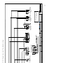
1
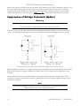
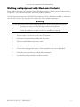
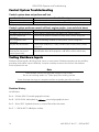
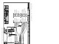
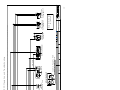
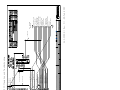
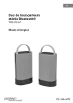
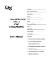
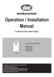
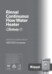
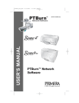
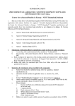
LOFA EP250 Operation and Troubleshooting
Introduction
This document provides general information on LOFA Industries EP250 control systems operation and
troubleshooting. EP250 control systems are a very flexible platform for diesel engine control, monitoring,
and protection, featuring LOFA’s powerful First Fault Diagnostics (FFD). After pinpointing the initial failure,
FFD stores it in memory and alerts the end user via a single bright LED. FFD monitors battery charge, low oil
pressure, high temperature, overspeed and up to three additional contact closure inputs. The field
configurable, expandable microprocessor-based solid-state design uses high-power semiconductors instead
of outdated electromechanical relays to ensure reliable high-current switching.
The EP250 features LOFA’s new modular Function Enhancement Packs (FEP). The plug-and-play FEP
modules allow various feature upgrades to be easily added to the standard platform. FEPs include:
•
•
•
•
•
•
Diagnostic Program Gauge (DPG)
Auto-Start with Real-time Clock
Data Logging
Closed Loop Speed Control
Precision Actuator Control
Custom OEM Solutions
The Diagnostic Program Gauge (DPG) features a backlit LCD display with three push buttons all in a
compact 2 inch gauge. The LCD is clearly readable in both bright sunlight as well as total darkness. The
DPG provides a complete user interface for other Function Enhancement Packs and allows each system to
be field configured to suit the customer's unique requirements. After configuring, the DPG can be removed
in cost-sensitive applications.
Some of the EP250 configurable features include:
•
•
•
•
•
Automatic preheat duration
Afterglow duration
Failure indication with shutdown or indication only
Over-speed shutdown
Normally open or normally closed shutdown switches
All standard panels include feature a 12 inch wiring harness terminating into a sealed weather proof plug.
This robust universal wiring connection performs well in harsh environments and allows interchanging a
number of different panels and harnesses. This design allows for simplified installation as well as a flexible
means to incorporate custom plug-and-play engine wiring harnesses and standard harness extension
Note
The engine harness is not included with the panel.
A number of standard engine harnesses are available or
LOFA can develop a custom harness for you exact needs.
Generic harnesses in various lengths are available for field customization.
463-3000-01 Rev C.1 - 28-Feb-2007
1
LOFA EP250 Operation and Troubleshooting
Warning
When replacement parts are required, LOFA Industries recommends using replacement parts
supplied by LOFA or parts with equivalent specifications.
Failure to heed this warning can lead to premature failure,
product damage, personal injury or death.
Important Safety Information
The warnings in this publication are not all inclusive.
LOFA Industries cannot anticipate every potential hazard.
Appropriate safety rules and precautions should be followed with any
tool, work method or operating procedure.
Improper procedures, tools and materials may cause
damage or make the equipment unsafe to operate.
Only persons with appropriate training, skills and tools
should perform these functions.
Improper operation, maintenance or repair of this product can be
dangerous and may result in injury or death.
Do not operate or perform any maintenance or repair on this product until all operation,
maintenance and repair information is read and understood.
The information, specifications, and illustrations in this publication are based on information
available at the time of publication.
All items are subject to change at any time without notice.
2
463-3000-01 Rev C.1 - 28-Feb-2007
LOFA EP250 Operation and Troubleshooting
Operation
Turning the control system key to the run position starts a self-test which causes all LEDs to illuminate once,
activates the alarm output for one second and enables the fuel run/stop solenoid output. After self-test, the
LEDs indicate the state of the inputs they monitor. The normal indications are battery charge and oil pressure
on most applications. If these LEDs are not illuminated at this time it may indicate the inputs are not properly
connected.
The Preheat LED is illuminated when the key switch is turned to the run position if automatic preheat is
configured or if an external preheat control is connected (See Preheat Options). Preheat time varies from
application to application. After waiting for the Preheat LED to extinguish, the engine is cranked by turning
and holding the key switch in the start position until the engine starts. The key switch is spring loaded to
return automatically to the run position when released. The Preheat LED is illuminated during afterglow if
enabled.
Note
The key switch is equipped with a mechanical start locking device.
An attempt to re-crank the engine can only be made by turning the key switch
to the off position to reset the start locking mechanism.
If the engine is not started within 10 seconds of turning on the system, the fuel run/stop solenoid output is
turned off to prevent battery discharge when the key switch is left in the run position. The fuel run/stop
solenoid output is turned off after 10 seconds even if preheating. As soon as the key switch is turned to the
start position the solenoid output is enabled. The afterglow cycle begins when the key switch returns to the
run position.
Note
If conditions do not warrant preheat, the engine may be started by turning the key to the start
position without waiting for the preheat time to expire.
Control system instrument power, including the hourmeter and voltmeter, is provided by the fuel run/stop
solenoid output. If the instruments do not power up when the key is turned to the run position, this indicates
a problem with the solenoid circuit (see Troubleshooting).
After the engine starts, the control system electronics ignore all shutdown conditions for the first 10 seconds.
This delay eliminates the requirement to hold a by-pass override button during starting and allows the system
conditions such as oil pressure to normalize. The 10 second timer starts when the key switch returns to the
run position.
Note
Starter input is required for correct system operation. If the starter motor input is not activated
(connected to battery positive) and the engine is started through another means (i.e. air
starter) the engine will shutdown 10 seconds after the key switch is turned to the run position.
463-3000-01 Rev C.1 - 28-Feb-2007
3
LOFA EP250 Operation and Troubleshooting
To prevent unintentional engine shutdowns caused by intermittent conditions (i.e., pressure spikes, coolant
movement) the control system requires a constant 1 second fault input to cause engine shutdown.
Warning
When used in combination with mechanical float type switches
engine vibrations may prevent constant contact closure.
The control system can be configured to shutdown with no delay.
See the EP250 Configuration Guide for detailed preheat control instructions.
The control system has the ability to shut down the engine for over speed. Over speed will be indicated via a
blinking Battery Charge LED. If the control system is equipped with the DPG, the display will also indicate
over speed shutdown. The control system senses RPM either by the frequency terminal of the alternator,
proximity switch or magnetic pick-up.
Preheat Options
Preheat Output
Preheat is a 1A output for control of an external power relay with predetermined preheat and afterglow
times. A relay should be selected with appropriate amperage capacity for the installed cold starting aid
(glowplug, intake air heater, etc.). Applications using multiple cold starting aids may require multiple relays.
Optional or additional components may allow preheat time to be modified by sensing ambient temperature.
Depending on specific configuration, this output may provide either high side (battery positive) or low side
(ground) control.
Note
Consult engine documentation when selecting cold starting aid,
power relay and heating specifications.
Preheat Indication Input
With this option, the preheat LED provides indication for an external preheat control system. Depending on
specific controls and configuration, this input can be configured to accept either high side (battery positive)
or low side (ground) control.
Indicators
Battery LED (Red)
A solidly illuminated Battery LED indicates a battery charge failure. A battery charge failure may be caused
by a faulty alternator, broken drive belt or the alternator not excited. A battery voltage reading of
approximately 14 volts on a 12 volt system (28 volts on a 24 volt system) while the engine is running
indicates the battery is charging properly. Irregular blinking of the Battery LED may indicate a failing charge
circuit. The system can be configured for battery charge failure to indicate only.
Overspeed Indication
A regularly blinking Battery LED indicates the configured overspeed RPM has been exceeded. The overspeed
RPM can be verified, changed or disabled (see the EP250 Configuration Manual for details).
4
463-3000-01 Rev C.1 - 28-Feb-2007
LOFA EP250 Operation and Troubleshooting
Oil Pressure LED (Red)
A solidly illuminated Oil Pressure LED indicates low oil pressure failure. The control system typically senses
low oil pressure from a ground contact switch on the engine. When a sender/switch combination is used on
the engine, the marking WK generally indicates the switch terminal. This input typically expects a normally
closed switch (ground contact when oil pressure is low). A defective switch or shorting the shutdown input to
ground can cause low pressure fault indication. Additionally, when using sender/switch combinations,
swapping the WK and G terminal can cause unintended shutdowns. The system can be configured for oil
pressure failure to indicate only.
Warning
Low oil pressure is not an indication of low oil level.
For best possible protection LOFA recommends using
our solid-state oil level shutdown switch.
Note
Most shutdown switches are grounded through the switch body.
Do not use insulating sealant (i.e. Teflon tape) when installing switches.
Temperature LED (Red)
A solidly illuminated Temperature LED indicates high engine temperature failure. The control system typically
senses high temperature from a ground contact switch on the engine. When a sender/switch combination is
used on the engine, the marking WK or W generally indicates the switch terminal. This input typically expects
a normally open switch (ground contact when engine temperature is too high). A defective switch or shorting
the shutdown input to ground can cause over temperature fault indication. Additionally, when using
sender/switch combinations, swapping the WK or W and G terminal can cause unintended shutdowns. The
system can be configured for temperature failure to indicate only.
Warning
If the temperature switch is not in contact with coolant due to
coolant loss the engine is not protected from overheating.
For best possible protection, LOFA recommends using
our solid-state coolant level shutdown switch.
Note
Most shutdown switches are grounded through the switch body.
Do not use insulating sealant (i.e. Teflon tape) when installing switches.
Some thermostat housings are composites and do not provide ground for the switch.
AUX 1 LED (Red)
A solidly illuminated AUX 1 LED indicates auxiliary 1 failure (i.e., coolant level, oil level, belt breakage,
hydraulic pressure, etc.). The control system typically senses failure using a ground contact switch. Auxiliary
inputs are equipment specific and determined by the equipment manufacturer. A defective switch or shorting
463-3000-01 Rev C.1 - 28-Feb-2007
5
LOFA EP250 Operation and Troubleshooting
the shutdown input to ground can cause fault indications. The system can be configured for auxilary 1 failure
to indicate only.
A blinking AUX 1 LED indicates SW input failure. The control system typically senses failure using a ground
contact switch. The SW input is equipment specific and determined by the equipment manufacturer. A
defective switch or shorting the shutdown input to ground can cause fault indications.
AUX 2 LED (Red)
A solidly illuminated AUX 2 LED indicates auxiliary 2 failure (i.e., air flow restriction, fuel level, etc.) but by
default does not cause a shutdown. The control system typically senses failure using a ground contact switch.
Auxiliary inputs are equipment specific and determined by the equipment manufacturer. A defective switch or
shorting the shutdown input to ground can cause fault indications. The system can be configured for auxilary
2 failure to indicate only.
Preheat LED (Red)
A solidly illuminated Preheat LED is the system preheat indication. When the LED extinquishes the preheat
period is complete and the engine may be cranked. The LED illuminates again to indicate afterglow.
Gauges
Voltmeter
The voltmeter is connected to the fuel run/stop solenoid output. If the voltmeter does not indicate in the run
position, this indicates a problem with the solenoid circuit. A battery voltage reading of approximately 14
volts on a 12 volt system (28 volts on a 24 volt system) while the engine is running indicates the battery is
charging properly.
Tachometer
The tachometer indicates engine RPM using a frequency signal derived from the engine. This signal may be
provided by an alternator frequency tap, proximity switch. An optional amplifier/divider can be added for
use with a magnetic pickup.
Note
If the alternator is not excited (not charging),
no frequency is generated and the tachometer will indicate 0 RPM.
The tachometer is factory calibrated to indicate correctly when the panel is preconfiguring or field calibrated
with a Diagnostic Programming Gauge (DPG). The tachometer can be calibrated using standard procedures
if the configuration is not performed (see Tachometer Calibration Instuctions for details).
Oil Pressure Gauge
The gauge measures oil pressure with a resistance sender on the engine referenced to ground. When a
sender/switch combination is used on the engine, the marking G generally indicates the gauge terminal. The
gauge expects a low resistnace for low pressure and a higher resitance for higher pressure. If the gauge is
not connected to the sender, the gauge will read full scale (pegged). A defective sender or shorting the
gauge input to ground will cause the gauge to read 0 pressure. When using sender/switch combinations,
swapping the WK and G terminal prevents the gauge from working and may cause unintended shutdowns.
6
463-3000-01 Rev C.1 - 28-Feb-2007
LOFA EP250 Operation and Troubleshooting
Warning
Low oil pressure is an indication of engine wear,
not an accurate indication of low oil level.
Note
Senders and gauges must be matched to indicate correctly.
Most senders are grounded through the sender body.
Do not use insulating sealant (i.e. Teflon tape) when installing senders.
Temperature Gauge
The gauge measures engine temperature with a resistance sender on the engine referenced to ground.
When a sender/switch combination is used on the engine, the marking G generally indicates the gauge
terminal. The gauge expects a high resistnace for low temperatures and a lower resitance for higher
temperatures. If the gauge is not connected to the sender, the gauge will read 0. A defective sender or
shorting the gauge input to ground will cause the gauge to read full scale (pegged). When using
sender/switch combinations, swapping the WK and G terminal prevents the gauge from working and may
cause unintended shutdowns.
Warning
If the temperature sensor is not in contact with coolant due to coolant loss
the gauge will not accurately indicate engine temperature.
Note
Senders and gauges must be matched to indicate correctly.
Most senders are grounded through the sender body.
Do not use insulating sealant (i.e. Teflon tape) when installing senders.
Some thermostat housings are composites and do not provide ground for the sender.
Hourmeter
The hourmeter is connected to the fuel run/stop solenoid output. If the hourmeter does not count in the run
position, this may indicate a faulty hourmeter or a problem with the solenoid circuit. If the engine shutsdown
or is not started within 10 second the hourmeter stops counting.
Additional Gauges
Additional gauges can be added by removing blind covers and installing the gauge. Power connections are
provided with the standard configuration.
463-3000-01 Rev C.1 - 28-Feb-2007
7
LOFA EP250 Operation and Troubleshooting
Harness
Sealed Connectors
The provided sealed weather proof plug includes a grey locking device which must be released to separate
the connectors. Press the tab on the connector housing to release the connectors.
Warning
LOFA does not recommend using dielectric grease or sealant with sealed connectors.
These chemicals may cause seal damage and allow water entry.
Use LOFA provided cavity plugs to seal the connector if wires are removed.
Unsealed Connectors
For unsealed connectors exposed to the elements, LOFA recommends using dielectric grease to protect
contacts.
Warning
LOFA does not recommend using sealant with unsealed connectors.
Sealant traps moisture in the connector and encourages corosion.
Harness Routing
The minimum routing of radius of the wiring harnesses should be at least two times the diameter of the
wiring harness. Bends should be avoided within 1 inch (25 mm) of any connector in order to avoid seal
distortion allowing moisture to enter the connector.
Note
For harness length in excess of 10 ft a relay must be added to the start solenoid circuit.
LOFA offers starter relay kits for mounting near the engine.
8
463-3000-01 Rev C.1 - 28-Feb-2007
LOFA EP250 Operation and Troubleshooting
Battery Circuit Requirements
Battery Positive Connection
The electronic control system operates on either a 12 VDC or 24 VDC electrical systems. The unswitched
battery positive connection to the control system is made at the weather proof connector. The control system
provides switched positive battery protected by a 15 Amp fuse (12 V or 24 V system).
Protection for the unswitched battery positive circuit is dependent on specific equipment configuration. The
overload protection should not exceed 125% of the sum of all output currents plus 5 Amps for the control
system. Powering the control system through dedicated circuits with appropriate overload protection reduces
the possibility of system damage.
Circuit breakers are preferred over in-line fuses for circuit protection. Over current protection devices should
ideally be located in a central location. If automatic reset circuit breakers are used, consideration of the
environment of the breaker is critical and may affect the trip point. The trip point of some circuit breakers
can be significantly reduced below the rated trip point if the circuit breaker is exposed to high temperatures.
Warning
Disconnecting the battery while the engine is running
may damage electrical components.
When using a battery disconnect switch, LOFA recommends using a
2 pole switch to disconnect both the battery and alternator output.
Battery Negative Connection (Grounding)
Warning
Improper grounding can cause electrical noise, unreliable operation and may damage the
control system or other components. All ground connections must be free from foreign
materials, including paint, which may interfere with proper grounding.
A reliable ground must be provided for the control system.
LOFA recommends the ground connection be made directly to the battery negative.
Grounding through frame members is not recommended.
All ground paths must be capable of carrying any likely fault currents.
Do not reverse the battery polarity. Attempting to crank the engine when the polarity of the
battery connections is reversed may damage the control system.
Note
A maximum of three ring terminals should be connected to a ground stud in order to ensure
integrity of the ground connection. The use of more than three terminals can cause the
connection to become loose.
Voltage Drop
If control system voltage drops below 6 volts for more than one tenth of a second, the control system may
reset causing the self test to reactivate and the engine to shutdown after 10 seconds. Resetting the control
463-3000-01 Rev C.1 - 28-Feb-2007
9
LOFA EP250 Operation and Troubleshooting
system is equivalent to quickly turning the key switch to off and back to run without starting the engine. Since
the control system did not sense a start signal, the fuel run/stop solenoid deactivates after 10 seconds.
Voltage drops can be caused by transients from external equipment, improper wire sizes, faulty wiring or
nearby lightning strikes. In the absence of a LOFA Power Box, relays may be needed for long wire runs.
Suppression of Voltage Transients (Spikes)
Warning
The installation of voltage transient suppression at the transient source is required.
LOFA follows SAE recommended electrical environment practices.
Inductive devices such as relays, solenoids and motors generate voltage transients and noise in electrical
circuits. Unsuppressed voltage transients can exceed SAE specifications and damage electronic controls.
I
Relays and solenoids with built-in voltage transient suppression diodes are recommended whenever possible.
Refer to the illustration for proper installation of diodes when built-in voltage transient suppression is not
available.
Locate inductive devices as far as possible from the components of the electronic control system. When
using electric motors it may also be necessary to add isolation relays to eliminate voltage transients, noise
and prevent back feed.
Note
LOFA harness assemblies typically include all required engine control suppression devices.
Added equipment will require additional protection.
10
463-3000-01 Rev C.1 - 28-Feb-2007
LOFA EP250 Operation and Troubleshooting
Welding on Equipment with Electronic Controls
Proper welding procedures are required to avoid damage to electronic controls, sensors, and associated
components. The component should be removed for welding if possible.
The following procedure must be followed if the component must be welded while installed on equipment
with electronic controls. This procedure will minimize the risk of component damage.
Warning
Do not ground the welder to electrical components such as the control ground or sensors.
Improper grounding can cause damage to electrical components
Clamp the ground cable from the welder to the component being welded. Place the clamp
as close as possible to the weld to reduce the possibility of damage.
1.
Stop the engine. Turn the key switch to the OFF position.
2.
Disconnect the negative battery cable from the battery.
3.
Open any installed battery disconnect switch.
4.
Unplug the control system if possible.
5.
Connect the welding ground cable as close as possible to the area to be welded.
6.
Protect the wiring harness from welding debris and spatter.
7.
Use standard welding methods to weld the materials.
463-3000-01 Rev C.1 - 28-Feb-2007
11
LOFA EP250 Operation and Troubleshooting
General Troubleshooting
For additional information, refer to engine manufacturer troubleshooting guide.
No response from starter motor
Possible Cause
No battery voltage to starter
Battery discharged
Tripped overcurrent protection
No signal from control system
Defective starter solenoid
Defective starter motor
Possible Remedy
Verify wiring and battery connection (power and ground)
Charge or replace battery, verify alternator charging
Correct fault, replace or reset overcurrent protection
No power to control system (see Control System Troubleshooting below)
Replace starter solenoid
Replace starter motor
Engine will crank but not start
Possible Cause
Engine not getting fuel
Fuel run/stop solenoid not
engaged
Tripped overcurrent protection
No preheat (cold condition)
Possible Remedy
Check fuel level, filter, fuel pump, verify no air in fuel lines
See Fuel Solenoid Run/Stop Troubleshooting (below)
Correct fault, replace or reset overcurrent protection
See Preheat Troubleshooting
Engine runs for 10 seconds and shuts down
Possible Cause
Shutdown switch input active
Battery not charging
Control board did not sense
start signal
Defective control system
Possible Remedy
Verify shutdown source exists, correct condition or correct faulty circuit
Verify alternator charging (see Alternator not charging battery below)
Engine started through alternate method (i.e., manual air start, push start,
etc.)
See Control Panel Troubleshooting (below)
Engine runs longer than 10 seconds and shuts down
Possible Cause
Shutdown switch input active
Circuit overload protection
tripped
Voltage transients (spikes)
Defective control system
Possible Remedy
Correct engine fault, verify shutdown switch wiring
Correct overload, keep control system from overheating
(over 185° F/85° C)
Add suppressor diodes, protect from nearby lightening strikes, shield
induced spikes from other equipment, add electric motor control relay
See Control System Troubleshooting (below)
Alternator not charging battery
Possible Cause
Broken or slipping alternator
drive belt
Alternator not excited
Alternator output not
connected
Alternator not grounded
Alternator faulty
12
Possible Remedy
Adjust or replace alternator drive belt
Verify excitation circuit connected, replace faulty regulator, add additional
excitation resistor
Install charge wire
Clean or add ground connection
Replace faulty alternator
463-3000-01 Rev C.1 - 28-Feb-2007
LOFA EP250 Operation and Troubleshooting
Fuel Run/Stop Solenoid Troubleshooting
Engine does not stop immediately
Possible Cause
Back feed from motor (i.e.,
cooling fan)
Sticking solenoid linkage
Fuel valve without check valve
Possible Remedy
Add relay or blocking diode
Repair or replace solenoid linkage
Install or repair check valve
Fuel run/stop solenoid does not engage
Possible Cause
No power to solenoid
No power to solenoid pull coil
Incorrect linkage adjustment
Faulty solenoid
Failed suppressor diode
Optional e-stop engaged
Possible Remedy
Locate reason for lack of power and correct (Circuit overloaded? Failed
suppressor diode? Faulty wiring?)
Correct faulty wiring, check pull control circuit (see Power Box
Troubleshooting below)
Adjust solenoid linkage
Replace solenoid
Correct wiring (diode reversed?), replace suppressor diode
Disengage e-stop
Engine not getting fuel
Possible Cause
Empty fuel tank
Clogged filter
Air in fuel lines
Low fuel pressure
Faulty fuel pump
Possible Remedy
Fuel engine
Replace filter
Bleed fuel lines
Replace faulty fuel pump and/or clogged filter
Replace fuel pump, correct wiring fault (electric fuel pump)
Preheat Troubleshooting
Engine is hard to start in cold conditions
Possible Cause
Start attempt before preheat
complete
Incorrect preheat specification
Heater faulty
Heater relay faulty
Preheat control not functioning
Faulty control system
Possible Remedy
Wait for preheat time to elapse, crank as soon as time elapses
Correct control system configuration, install correct control system
Replace heater
Replace relay
Correct wiring, correct control system configuration
See Control System Troubleshooting (below)
Engine produces excessive white smoke after starting
Possible Cause
Afterglow not enabled
Heater faulty
Heater relay faulty
Preheat control not functioning
Faulty control system
Possible Remedy
Reconfigure control system
Replace heater
Replace relay
Correct wiring, correct control system configuration
See Control System Troubleshooting (below)
463-3000-01 Rev C.1 - 28-Feb-2007
13
LOFA EP250 Operation and Troubleshooting
Control System Troubleshooting
Control system does not perform self test
Possible Cause
Tripped overcurrent protection
Faulty connection to battery
Possible Remedy
Correct fault, replace or reset overcurrent protection
Correct battery connections (see Battery Circuit Requirements above)
Control system performs normal self test, engine cranks, runs and shuts down
Possible Cause
Only Battery LED illuminated
Only Oil Pressure LED
Illuminated
Only Temperature LED
Illuminated
Only Aux LED Illuminated
All normally closed shutdowns
illuminate for one second
(control system reset)
Possible Remedy
Correct battery charge failure (see Battery not charging above)
Correct low oil pressure condition or faulty switch, correct wiring fault
Correct overheating condition or faulty switch, correct wiring fault
Correct fault condition (i.e. v-belt, coolant level) or faulty switch, correct
wiring fault
Add suppressor diodes, protect from nearby lightening strikes, shield
induced spikes from other equipment, add electric motor control relay
Testing Shutdown Inputs
Shutdown switches signal a fault by ground contact in most systems. Shutdown operation can be verified by
grounding the shutdown inputs individually. It may be necessary to remove the wire from the shutdown
switch to perform this test.
Note
Most shutdown switches are grounded through the switch body.
Do not use insulating sealant (i.e. Teflon tape) when installing switches.
Some thermostat housings are composites and do not provide ground for the switch.
Revision History
Initial Release.
Rev A – 22-May-2006. Corrected typographical errors.
Rev B – 26-Oct-2006. Add symbols to Indicators, corrected typographical errors.
Rev C – 8-Jan-2007. Updated schematics, removed Power Box information.
Rev C.1 – 28-Feb-2007. Added part numbers.
14
463-3000-01 Rev C.1 - 28-Feb-2007
463-3000-01 Rev C.1 - 28-Feb-2007
The following pages show typical schematics.
Details vary from installation to installation.
See the specific schematics for installation for details.
Typical Schematics
LOFA EP250 Operation and Troubleshooting
15
16 AWG Blac k
16 AWG B lac k
16
+
-
16 AWG Black
0000
Hourmeter
G6
Voltmeter
+
+
-
G5
+
G4
+
+
-
-
-
Pressure
G3
+
-
+
+
+
G2
Customer
Supplied
-
16 AWG Black
-
-
-
G1
16 AWG Red
16 AWG Red
16 AWG Red
16 AWG Red
16 AWG Red
16
AW
16
G
W
R
ed
hi
te
AW
G
16
G
AW
1
Bl
k
ac
G
W
6A
ue
Bl
16 AWG Orange
FLT2
16 AWG White
FLT1
16 AWG Tan
16 AWG Black
16 AWG Black
16 AWG Grey
J16
6
5
4
3
2
1
6 Pos. Black
Sol2
Sol+
X5
X3
K1-30
K1-87a
31
K1-87
k1-87
K1-85
Aux 2
Aux 1
Sw
Alm
Gnd
Gnd
15F
Prh
Temp
PSI
W
Sol+
1 D+
2 W-G
3 19-17
1
2
3
4
5
6
X10 K4-87a
X8
X7
Battery
BD2
15A
Sol+
15
15
50
50
50
D+ Alternator
Solenoid
Aux Switch 1
Temp Switch
Aux Switch 2
Pressure Switch
Ground
Ground
Starter (50)
Accessory (15)
Tachometer
Preheat Control
Pressure Gauge
Temp Gauge
EP-250
BD1
Part Number:
Description:
9
8
7
6
5
4
3
2
1
14
13
12
11
J31
16 AWG Blue
16 AWG Orange
16 AWG White
16 AWG Green
14 AWG Purple
16 AWG Yellow
16 AWG Yellow/Blue
16 AWG Yellow/Black
16 AWG Yellow/Orange
16 AWG Black
14 AWG Purple
14 AWG Red
14 AWG Red/Black
14 AWG Red
14 AWG Red
14 AWG Red/Black
12 AWG Red
250 Hembree Park Dr Ste 122
EP250 Panel With AutoStart And Float Level Switch
1
2
3
4
5
6
7
8
9
10
11
12
13
14
J16
10
X4
X1
X9
X11
31 1
30 2
30 3
31 4
50f
58
1
Aux Relay
2
D+ Alternator
3
Thermistor
4
Tachometer
5
Ground
6
AutoStart
7
Ground
8
Alarm
Pressure Switch 9
Auto Power (58) 10
Pressure Switch 11
Preheat Control 12
13
Starter (50)
14
Solenoid
MSS200
INTERFACE
Prehea t
K4-87
Temp
X6
PSI
16 A WG B lack
Rev
19
19
9
4
14 AWG Purple
Date: 12/15/05
phone: 770-569-9828
16 AWG Black
Drawn By: MThiam
12 AWG Red
16 AWG Black
J33
17
3
2
30
17
1
30
KS1
Roswell GA 30076
J32
58
50A
8
10
15
7
15
6
5
Solenoid
Ground
Ground
Aux Switch 1
Starter (50)
Battery (30)
D+ Alternator
.XXX
.005
fax: 770-569-9829
.XX
.02
P2
P1
ANGº
2º
8
7
6
5
4
3
2
1
8
7
6
5
4
3
2
1
of
1
Solenoid
Ground
INDUSTRIES, INC.
MANUFACTURER OF QUALITY ENGINE COMPONENTS
Pressure Switch
Pressure Gauge
Temp Switch
Temp Gauge
Aux Switch 2
Tachometer
Ground
Ground
Solenoid
D+ Alternator
Battery (30)
Starter (50)
Aux Switch 1
www.LOFA.net
Sheet
8
7
6
5
4
3
2
1
8
7
7
5
4
3
2
1
463-3000-01 Rev - C.1 - 28-Feb-2007
Tolerances
+/-
.X
.1
Pressure Gauge
Pressure Switch
Ground
Solenoid
Tachometer
Aux Switch 2
Temp Gauge
Temp Switch
J35
8
7
6
5
4
3
2
1
J34
8
7
6
5
4
3
2
1
THE INFORMATION CONTAINED IN THIS DRAWING IS CONFIDENTIAL AND THE SOLE PROPERTY OF LOFA INDUSTRIES INC. Reproduction or dissemination in whole or in part in any form or medium without express priorwritten permission of LOFA INDUSTRIES INC is prohibited.
Aux 1
16 A WG Black
16 A WG Black
LOFA EP250 Operation and Troubleshooting
Aux 2
2
R
Aux Switch 1
Solenoid
D+ Alternator
Battery+ (30)
Starter (50)
J1
8
16 AWG Green
14 AWG Purple
4
5
J2
8
7
IG
L
Ground
12 AWG Red
3
B+
Kubota Alternator
Wiring Diagram
R
Battery
BAT1
16 AWG Yellow
12 AWG Red/Black
2
6
16 AWG Tan
1
Delco Alternator
Wiring Diagram
Preheat Control
B+
16 AWG Yellow/Orange
6
463-3000-01 Rev C.1 - 28-Feb-2007
1
16 AWG Orange
5
Preheat
Unit
16 AWG Yellow/Blue
4
SW1
Aux 1
Shutdown
16 AWG Blue
3
16 AWG Black
16 AWG Yellow/Black
2
7
16 AWG White
1
8 Pos White
Ground
Pressure Switch
Pressure Gauge
Temp Switch
Temp Gauge
Aux Switch 1
Tachometer
86
87
87a
30
85
Part Number:
Description:
Power
Relay
CR1
8 AWG Red
CB1
31
D+
Rev
Roswell GA 30076
Drawn By: MThiam
Red 12 AWG To P1/P
W
Date:
phone: 770-569-9828
Tolerances
+/-
ALT1
Bosch Alternator
B+
14 AWG Purple To P1/H
MC-536 Generic Engine Schematic W/ Yellow And White Connectors
250 Hembree Park Dr Ste 122
50
MOT1
Starter Motor
3 Wire Solenoid
Wiring Diagram
Aux 2
Shutdown
Indication Only
SW1
30
8 AWG Red
.XX
.02
.XXX
.005
fax: 770-569-9829
.X
.1
ANGº
2º
SOL3
Shutdown
Solenoid
G
1
of
1
INDUSTRIES, INC.
17
MANUFACTURER OF QUALITY ENGINE COMPONENTS
-G = Gauge
www.LOFA.net
Sheet
G
PS1
Oil Pressure
Sender/Switch
N./C.
WK
Note: -WK = Switch
Temperature
Sender/Switch
N./O.
TS1
WK
THE INFORMATION CONTAINED IN THIS DRAWING IS CONFIDENTIAL AND THE SOLE PROPERTY OF LOFA INDUSTRIES INC. Reproduction or dissemination in whole or in part in any form or medium without express prior written permission of LOFA INDUSTRIES INC is prohibited.
P ull
8 Pos Yellow
LOFA EP250 Operation and Troubleshooting
Hol d
J1
-
-
-
-
-
J7
+
-
18
J5
6.3mm PosLock
+
+
+
+
G5
G4
G6
0000
Hourmeter
+
6.3mm PosLock
J15
6.3mm PosLock
-J13
16
6.3mm PosLock
+ J11
+
AW
G
W
hi
AW
G
te
R
ed
A
G
a
Bl
W
A
G
W
16
ck
ue
Bl
16 AWG Orange
6.3mm PosLock
J8
16
16
Low Float
N.O.
FLT2
6.3mm PosLock
16 AWG Black
6.3mm PosLock
J14
6.3mm PosLock
J2
G3
Voltmeter
J10
J2
6.3mm PosLock
+
+
6.3mm PosLock
G2
Pressure
6.3mm PosLock
J9
-
G1
16 AWG Black
Customer
Supplied
J4
6.3mm PosLock
J6
-
6.3mm PosLock
J3
-
6.3mm PosLock
16 AWG Black
16 AWG Blac k
16 A WG Red
16 AWG Red
J16
6
5
4
3
X5
J22
6.3mm PosLock
J18
6.3mm PosLock
J19
6.3mm PosLock
J20
6.3mm PosLock
J21
6.3mm PosLock
16 AWG White J17
6.3mm PosLock
High Float
N.O.
FLT1
16 AWG Tan
16 AWG Black
16 AWG Black
16 AWG Grey
2
1
6 Pos. Black X3
K1-30
K1-87a
31
K1-87
k1-87
K1-85
Aux 2
Aux 1
Sw
Alm
Gnd
Gnd
15F
Prh
Temp
PSI
W
Sol+
1 D+
2 W-G
3 19-17
1
2
3
4
5
6
X10 K4-87a
X8 Sol2
X7 Sol+
BD2
15A
Sol+
15
15
50
50
50
Part Number:
Description:
12 AWG Red/Black
1
2
3
4
5
6
7
8
9
10
11
12
13
14
14
13
12
11
10
9
8
7
6
5
4
3
2
1
J31
16 AWG Pink Black
16 AWG White
16 AWG Tan
16 AWG Orange
16 AWG Blue
16 AWG Yellow
16 AWG Yellow/Blue
16 AWG Yellow/Black
16 AWG Yellow/Orange
16 AWG Black
16 AWG Green
14 AWG Purple
J30
14 AWG Purple
6.3mm PosLock
14 AWG Red
J29
6.3mm PosLock
J286.3mm PosLock
J16
250 Hembree Park Dr Ste 122
Rev
12 AWG Red
14 AWG Red
14 AWG Red
6.3mm PosLock
J27
PosLock
J266.3mm
14 AWG Red/Black
PosLock
J256.3mm
6.3mm PosLock
EP-250 Panel W/ GT Connector And AutoStart
D+ Alternator
Solenoid
Aux Switch 1
Temp Switch
Aux Switch 2
Pressure Switch
Ground
Ground
Starter (50)
Accessory (15)
Tachometer
Preheat Control
Pressure Gauge
Temp Gauge
EP-250
BD1
X4
X1
X9 J24
6.3mm PosLock
X11 J23
31 1
30 2
30 3
31 4
50f
58
1
Aux Relay
2
D+ Alternator
3
Thermistor
4
Tachometer
5
Ground
6
AutoStart
7
Ground
8
Alarm
Pressure Switch 9
Auto Power (58) 10
Pressure Switch 11
Preheat Control 12
13
Starter (50)
14
Solenoid
MSS200
INTERFACE
Prehe a t
K4-87
Battery
16 AWG Red
16 AWG Red
16 AWG Red
Temp
X6
PSI
16 AWG B la c k
19
19
9
Roswell GA 30076
4
3
2
1
Date:
phone: 770-569-9828
J33
17
17
30
30
KS1
Drawn By: MThiam
J32
58
50A
8
10
15
7
15
6
5
.XX
.02
.XXX
.005
fax: 770-569-9829
.X
.1
ANGº
2º
of
1
www.LOFA.net
Sheet
Starter (50)
Ground
INDUSTRIES, INC.
MANUFACTURER OF QUALITY ENGINE COMPONENTS
Pressure Switch
Temp Switch
Aux Switch 1
Aux Switch 2
Solenoid
Battery+ (30)
Preheat Control
Pressure Gauge
Temp Gauge
D+ Alternator
Tachometer
Accessory (15)
P1
P
N
M
L
K
J
H
G
F
E
D
C
B
A
GT 150/280
Mix Male
463-3000-01 Rev - C.1 - 28-Feb-2007
Tolerances
+/-
12 AWG Red
THE INFORMATION CONTAINED IN THIS DRAWING IS CONFIDENTIAL AND THE SOLE PROPERTY OF LOFA INDUSTRIES INC. Reproduction or dissemination in whole or in part in any form or medium without express priorwritten permission of LOFA INDUSTRIES INC is prohibited.
Aux 1
16 AWG B lac k
16 A WG B lack
LOFA EP250 Operation and Troubleshooting
Aux 2
2
B+
R
16 AWG Black
P1
P
IG
Ground
Preheat
Unit
L
16 AWG Yellow/Orange
M
B+
R
Battery
BAT1
16 AWG Yellow/Blue
L
16 AWG Red
16 AWG Yellow
K
Power
Relay
86
87
87a
30
85
CR1
8 AWG Red
12 AWG Red
Part Number:
Description:
31
250 Hembree Park Dr Ste 122
30
MOT1
50
8 AWG Red
Rev
D+
Roswell GA 30076
Drawn By: MThiam
3 Wire Solenoid
Wiring Diagram
MC-536 Engine Generic Diagram With GT Male
SW1
SW2
Aux 1
Aux 2
Shutdown Shutdown
Indicator Only
12 AWG Red/Black
16 AWG Yellow/Black
J
N
14 AWG Purple
H
12 AWG Red
16 AWG Orange
G
16 AWG Blue
E
16 AWG Tan
16 AWG Green
D
F
16 AWG White
C
14 AWG Pink/Black
B
A
463-3000-01 Rev C.1 - 28-Feb-2007
1
Starter (50)
Ground
Pressure Switch
Temp Switch
Aux Switch 1
Aux Switch 2
Solenoid
Battery+ (30)
Preheat Control
Pressure Gauge
Temp Gauge
D+ Alternator
Tachometer
Accessory (15)
Pull
Gt 14 Pos. Male
ALT1
Date:
W
phone: 770-569-9828
B+
Tolerances
+/-
.XX
.02
.XXX
.005
fax: 770-569-9829
.X
.1
SOL3
Shutdown
Solenoid
ANGº
2º
G
1
of
1
-G = Gauge
www.LOFA.net
Sheet
G
19
MANUFACTURER OF QUALITY ENGINE COMPONENTS
INDUSTRIES, INC.
PS1
Oil Pressure
Sender/Switch
N./C.
WK
Note: -WK = Switch
Temperature
Sender/Switch
N./O.
TAS1
WK
16 AWG Black
THE INFORMATION CONTAINED IN THIS DRAWING IS CONFIDENTIAL AND THE SOLE PROPERTY OF LOFA INDUSTRIES INC. Reproduction or dissemination in whole or in part in any form or medium without express priorwritten permission of LOFA INDUSTRIES INC is prohibited.
LOFA EP250 Operation and Troubleshooting
Hold