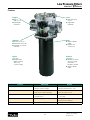
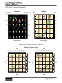
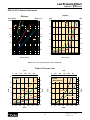
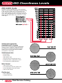
1
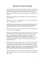
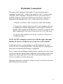
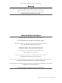
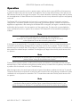
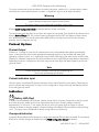
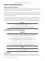
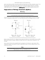
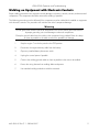
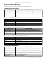
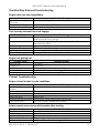
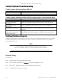
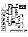
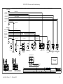
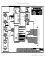
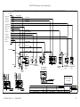
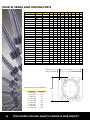
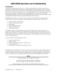
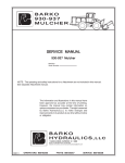
Texas International Oilfield Tools, Ltd.
Diesel Hydraulic Power Unit
Air and Electric Start
Installation, Operation and Maintenance
Table of Contents
Specifications…………………………………………………4
Safety Issues…………………………………………………..7
Component Locations………………………………………..9
Hydraulic Circuit Diagram…………………………………11
Hydraulic System Functioning……………………………..12
Hydraulic Connections……………………………………...13
Installation…………………………………………………...14
Operation…………………………………………………….15
Adjustment…………………………………………………...16
Service………………………………………………………...18
Hydraulic System Troubleshooting…………………………19
Electrical System Troubleshooting………………………….21
Deutz Engine Installation, Operation and Maintenance
Instructions……..………………………………….Appendix A
LOFA Engine Panel Operation, Troubleshooting, Circuit
Diagrams…………………………………………...Appendix B
Muncie Hydro-Throttle Installation, Adjustment, Parts List
and Troubleshooting………………………………Appendix C
2
Metaris Gear Pump Code Book Extract…………Appendix D
Parker Filter Data…………………………………Appendix E
ISO Fluid Cleanliness Levels……………………...Appendix F
3
Texas International Oilfield Tools, Ltd.
Diesel Hydraulic Power Unit Specifications
Length
Width
Height
110-1/2 inches
52 inches
62 inches
Frame
ASTM A36 steel construction
Skid eyes both ends
Lift eyes on top
Fully welded belly pan
Removable drain plug
Full length forklift tubes
Removable top
Weight, dry
Weight, full
3709 pounds
4821 pounds
Engine
Deutz F6L914 Air Cooled 6 Cylinder Diesel
119 horsepower @ 2500 rpm
295 ft-lbs torque @ 1500 rpm
Air or Electric Start
4
Hydraulic
tank capacity
Diesel tank
capacity
Performance
135 gallons maximum
118 gallons working
Sight and temperature gages
Filtered breather
Top access hatch
Fully welded steel construction
35 gallons maximum
33 gallons working
Top access filler
Fully welded steel construction
47 gpm @ 1800 rpm
66 gpm @ 2500 rpm
6 gallons per hour fuel consumption at maximum output
(approximately)
Maximum operating pressure 2500 psi (higher available)
Pump
Single stage, heavy duty gear type pump
6.38 cu in/rev
SAE B mount
SAE C splined shaft
Oil Cooler
Oil / air type, brazed bar & plate construction
Oversize cooler for hot climate use
Low pressure drop (< 18 psi) at max flow
Adjustable fan speed
Filtration
Full flow return line
Dirty element / No element / Operation OK sight gage
Remote start / stop if desired
Standard gages
Output pressure, 0 – 3000 psi, oil filled
Tank temperature
5
Standard gages
cont'd
Tank level
Filtration status
Optional gages
Voltmeter
Engine Temperature
Engine Oil Pressure
Engine hour meter
Tachometer
Battery
(Electric start
only)
Group type 8D, heavy duty 12 volt commercial battery
1300 cold cranking amps at 0 F., 1560 cold cranking
amps at 32 F.
435 reserve capacity minutes at 25 amps
20-3/4" L X 11" W X 10" H
Adjustable relief valve factory set at 2500 psi
6
Safety Issues
1. Location – always insure the unit is properly located away from
hazardous vapor sources, in a solid, level location.
2. Electrical wiring –Insure that connections are properly made, that there
are no breaks in the insulation, and that cables are running where they won’t
be cut, nicked or squeezed during operation.
3. Cooling – always operate the unit with cooling fan properly adjusted.
The temperature of the oil will increase 80 degrees Fahrenheit in 20 minutes
without air flow from the fan.
4. Hot surfaces and fluids – the hoses, pump, motor and tank surfaces can
get quite warm during normal operation, as does the hydraulic oil. Use
proper cooling to keep the operating temperature between 100 and 130
degrees Fahrenheit. Avoid contact with hot surfaces and oil.
7
High temperatures decrease the useful life of the hydraulic oil, the hoses and
the seals in the equipment being powered. Very high temperatures can cause
burns, as shown on the previous page.
5. Mechanical parts – don’t allow items like clothing or tools close to the
accessory drive. Don't let items intrude into the fan at the front of the engine.
The engine develops nearly 300 foot pounds of torque while running, and
foreign objects can be drawn in with great power at rapid speed. Keep
foreign objects away from these areas.
6. Safety lockout – use a safety lockout device or disconnect the battery or
air when servicing the unit.
7. Lifting – use only the lift eyes provided. If the unit is full of hydraulic oil
the center of mass is approximately in the center of the forklift tubes. If the
unit is empty, the center of mass is still between the forklift tubes, but biased
to the motor end. Don’t use the top lifting eyes unless all bolts holding the
top to the frame are properly installed.
8. Fluid levels – Low hydraulic fluid level can cause overheating, or in
worst cases severe damage to the pump and even the associated tools it’s
driving. Keep fluid up to at least the minimum on the sight gage. Observe
the filtration monitor to be sure it’s operating in the green ( OK ) range.
Change the filter if it’s not.
9. Pressure leaks – High pressure fluid can cut as effectively as a knife. Oil
forced into your body will be harmful. NEVER check a leaking high
pressure line by putting your hands or fingers near the leak. Stop the unit,
bleed off any pressure as required before checking or fixing any high
pressure leakage.
8
1
2
3
4
5
6
7
8
9
10
11
Component Locations
1. Breather cap and fill neck
2. Full flow return filter
3. Level gage and fluid thermometer
4. Return disconnect
5. Pressure disconnect
6. Bypass control
7. 0 – 3000 psi pressure gage
8. Relief valve (back side of block)
9. Cooling fan needle control valve
10. Gage panel / starting key
11. Hydro-throttle control
9
11
12
13
14
15
16
17
18
Component locations
11. Skid eyes (4)
12. Air cleaner
13. Battery box (electric start only)
14. Diesel tank filler neck
15. Forklift tube
16. Air / oil cooler
17. Tank outlet to pump inlet shutoff valve
18. Tank cleanout cover
10
Hydraulic Circuit Diagram
Red lines are pressure lines, aqua (blue) lines are return lines,
green lines are suction lines.
11
Hydraulic System Functioning
The diesel engine drives the single stage pump at a setting of 1800 rpm. The
pump draws hydraulic fluid from the tank and delivers hydraulic fluid up to
2500 psi on the pressure line, adjustable at the relief valve. The pump
delivers 47 gpm at 1800 rpm, and 66 gpm at the engine's maximum speed of
2500 rpm.
The engine is controlled by the hydro-throttle, which opens the throttle as
the load increases.
When the bypass valve is opened, the relief valve is vented directly back to
tank - output pressure is not available.
The 2500 psi setting is the maximum recommended output pressure for the
standard pump. Theoretically the unit could produce more at full engine
rated output, but pump life will be shortened, possibly dramatically.
The unit is slightly overpowered for long service life. Exceeding the factory
set pressures is not recommended.
Cooling is provided on the return line with an oversized air to oil cooler. The
cooler is capable of removing nearly half the entire horsepower rating in
heat, so keeping hydraulic temperatures low for safety and for system
longevity is easily achieved with a reasonable flow of cooling air.
Controlling the temperature is done by manually adjusting the flow rate of
oil to the fan motor while observing the thermometer in the sight gage
mounted on the tank.
Full filtration is provided on the return line. The filter is mounted on the top
of the tank, and has a filter condition indicator mounted on the side of the
filter housing. The condition indicator shows when the filter is operating
properly, is bypassing (dirty filter), or is missing. Keeping the filter in good
condition is strongly recommended, as dirt in the system will increase wear
in the pump, valving and connected tongs or other hydraulic tools.
Hoses and fittings have JIC swivel connections, SAE flange connections, or
NPT connections. There is a shutoff valve on the tank so it can be drained
and serviced.
12
Hydraulic Connections
The power unit is equipped with Snaptite 78 series quick disconnect
couplings (or equivalent), 1 inch for the supply line and 1-1/4 inch for the
return line. These couplings contain check valves to prevent the loss of
hydraulic oil during connection and disconnection. Proper connection is
required to fully open the check valve. Connect the hoses as follows:
1. Wipe the connections clean as required to remove dirt and dust.
2. Connect the 1 inch pressure hose to the 1 inch coupling on the unit
by engaging the mating coupling halves and forcing the connectors
together while rotating the threaded sleeve on the hose connector. Full
thread engagement is necessary for the check valve to be fully open.
3. Using the same method as used for the 1 inch hose, connect the 11/4 inch return hose.
NOTE: DO NOT attempt to connect hoses with the engine and pump
running. Be sure it is off and that no one can turn it on by mistake.
If either the pressure or return fittings are not fully tightened, the check
valve will cause a restriction in the flow. This can result in overheating the
fluid, poor tool operation and damage to equipment.
Hoses, connections and fittings should be chosen carefully so as not to cause
excessive restriction. Restriction in a hydraulic system equals pressure drop,
and pressure drop equals heat. Choose short, large inside diameter hoses
whenever possible over long, skinny ones.
Improper connection or restrictive circuits can cause a serious loss of power
and will generate heat uselessly.
13
Installation
The diesel hydraulic power unit requires a location where adequate air flow
and exhaust removal are available. It’s important to consider hydraulic line
losses from size, length and head in choosing where to put the unit. The
sizes of the hydraulic lines should be large enough to limit friction losses to
300 psi or less. This may mean using hoses larger than the connections on
the unit.
There should be at least three feet between the oil cooler and any wall or
obstruction. In the best conditions it will be facing open air.
The presence of hazardous locations should be compared with the rating of
the power unit for compatibility.
Ideally the unit will be located in a non-hazardous location, with excellent
ventilation, as close as possible to the equipment to be powered.
Transport the power unit using the only the lifting eyes, skid eyes or forklift
tubes provided. Attaching lifting slings to other points, or positioning forklift
forks in other positions can damage the unit and can be dangerous to
personnel.
Measures should be taken to insure the unit does not shift or move from its
intended position.
Always take care around the accessory drive on the front of the engine !
The motor develops almost 300 foot-pounds of torque and at 1800 rpm loose
clothing, long hair, etc., can be drawn in with incredible speed and power with disastrous results. Place the unit so personnel can pass easily around
this area.
Diesel exhaust can be lethal ! Be sure that ventilation can carry away the
exhaust fumes.
14
Operation
The unit comes preset from the factory with the relief valve set at 2500 psi.
See the “Adjustment” section on page 16 of this manual for how to change
this setting.
1. Review the Deutz engine manual, Appendix A, for detailed instructions
on start up, shut down and operation of the engine.
2. Check the condition of all hoses. Look for worn or scraped areas, bubbles,
wrinkles or any other indication that the hose may need replacement.
3. Be sure the tank is filled to the proper level with the specified hydraulic
oil. Be sure the shutoff valve to the pump inlet is fully open.
4. Insure the diesel tank has adequate fuel for the intended operations.
Refueling is most safely done with the engine OFF. Clean up any spills.
5. Verify that the equipment to be operated is properly connected to the
power unit as specified in the “Hydraulic Connections” section on page 13.
6. Be sure the equipment being operated is an “open center” hydraulic
circuit. This means that in the neutral position the circuit has full flow from
the inlet to the outlet. If not, a “closed center” adapter must be installed.
7. Verify that cooling air can freely flow through the oil cooler.
8. If disconnected, connect the battery or air supply. Turn the key to the ON
and then the START position on the main enclosure or on the remote
start/stop switch, or pull the "Engine Start" knob for air start units.
9. To turn the unit off, turn the key to OFF or press the “Stop” button.
10. If the power unit shuts down prematurely, verify that there is fuel in the
fuel tank. If this happens repeatedly there is an abnormal condition which
must be found and fixed before continuing operation.
15
Adjustment
Adjustments should be made with the oil at normal operating
temperature of 80 to 130 degrees F.
Relief valve adjustment screw (back side of this block)
The adjustment for the relief valve is located as shown above. Turning the
adjustment screw clockwise (in) raises the relief pressure: turning it
counterclockwise lowers the relief pressure. The screw takes a 5/32" Allen
wrench: the locknut for the screw a 9/16" wrench.
The relief valve setting can be determined by operating the unit with no
equipment connected to the quick disconnects, the bypass closed, and
observing the pressure reading on the panel gage.
DO NOT OPERATE THE UNIT WITH EQUIPMENT
DISCONNECTED FOR OVER FIVE MINUTES. THINGS WILL GET
VERY HOT.
It is NOT recommended to exceed the factory setting of 2500 psi. Doing
so will shorten the life of the pump, perhaps dramatically.
16
Adjustment (continued)
Fan speed needle valve adjustment
Rotating the needle clockwise (viewed from the top) slows down the fan.
Rotating it counter-clockwise speeds the fan up.
Muncie Hydro-Throttle
See Appendix C for adjustment procedure.
17
Service
Servicing of the power unit consists of periodic inspection, lubrication and if
necessary, adjustment. Repairs are covered under the Hydraulic System
Troubleshooting section beginning on page 19 or the Engine System
Troubleshooting section beginning on page 21.
The unit should be fully inspected at the start of every job.
Daily inspections should look for:
1) Worn, wrinkled, bubbled, leaking or broken hoses or other evidence of
damage;
2) Visual evidence of physical damage to the unit;
3) Loose, worn or improper electrical connections;
4) Proper hydraulic fluid level;
5) Once operating, the state of the filter.
As most items in the unit are lubricated by the hydraulic fluid, they don’t
require other lubrication than to insure the hydraulic fluid is clean.
The engine does require periodic oil and filter changes. Under moderately
dirty conditions the engine oil should be changed every 500 hours. Under
severe conditions this should be done every 250 hours.
Hydraulic oil should be a good quality mineral based ISO VG 46 hydraulic
oil, such as Mobil DTE 25. Many others are suitable as well. Use of
vegetable based, water based hydraulic fluids or the like may damage the
pump and valving.
18
Hydraulic System Troubleshooting
Additional troubleshooting info is available in the appendices covering individual
components.
Problem
Pump excessively noisy.
Suction side plumbing is restricted or
blocked.
Viscosity of oil is too high.
Air in suction side.
Loose or worn out parts.
Corrective action
Insure that no foreign matter is blocking
the tank outlet by removing the access
hatch and looking inside.
Verify suction shutoff valve is wide open.
Change the oil to a lower ISO VG grade.
Pour oil over suction side fitting
connections. If noise stops, disassemble
fittings, re-tape and re-assemble.
Verify assembly is properly tightened,
replace worn out parts.
Hydraulic system overheating.
Insufficient cooling air.
Relief valve setting too high.
Viscosity of oil is too low or too high.
Excessive internal leakage.
Excess friction.
Leaks in pump, high volume check valve,
unloader valve, relief valve.
Dirty heat exchanger.
Verify air flow rate is unobstructed. Open
needle valve fully.
Reset relief valve to a maximum of 2500
psi.
Change the oil.
Check parts for wear and repair or replace
as necessary. Check for contamination and
clean out crud as needed.
Check the moving parts inside the pump
for tightness and proper fit. Repair as
required.
Repair or replace.
Clean out oil and air passages.
Excessive wear of moving parts
Abrasive contaminants in oil.
Engine to pump alignment off.
Operating pressure is set too high.
Viscosity of oil is too low.
Leakage of air into the system.
Clean and flush system. Replace filter
element. Clean breather. Replace fluid.
Verify fastener tightness. If OK, replace
motor to pump housing and coupling.
Reset relief valve lower, to a maximum of
2500 psi.
Change oil to a higher ISO VG grade.
Pour oil over suction side fitting
connections. If the oil disappears,
disassemble, re-tape and re-assemble.
19
Problem
Flow rate (tool speed) is low.
Pump inlet flow is restricted.
Damaged or worn pump parts.
Oil is bypassing through relief or unloader
valves.
Disconnect fittings not tightened.
Oil viscosity low or high.
Plumbing is too restrictive.
Engine speed is low.
Corrective action
Insure that no foreign matter is blocking
the tank outlet by removing the access
hatch and looking inside.
Verify suction shutoff valve is wide open.
Inspect the parts and replace as necessary.
Check relief and unloader valves for proper
operation and reset as necessary.
Check that fittings are tightened per
“Hydraulic Connections” section.
Change to proper viscosity grade.
Change to larger and/or shorter hoses.
Insure Hydro-Throttle is operational. When
supplying pressure engine rpm should be
between 1800 and 2500.
20
Engine System Troubleshooting
Additional troubleshooting info is available in the appendices covering individual
components.
Problem
Engine will not start.
No electrical power.
Battery dead.
Control circuit wiring incorrect or
disconnected.
Air in fuel system.
Corrective action
Verify and repair power connections.
Recharge battery then find source of drain.
Verify wiring is correct. Tighten
connections.
Bleed fuel system (See Appendix A section
3.1.4.
Engine stalls.
Control circuit wiring incorrect or
disconnected.
Dirty fuel filter.
Air in fuel system.
Verify wiring is correct. Tighten
connections.
Replace fuel filter
Bleed fuel system (See Appendix A section
3.1.4.
Engine runs and then slows or
stops
Control circuit wiring incorrect or
disconnected.
Engine overloaded.
Dirty fuel filter.
Air in fuel system.
Verify wiring is correct. Tighten
connections.
Adjust or replace hydraulic valves. Be sure
hoses are properly connected to tool(s).
Replace fuel filter
Bleed fuel system (See Appendix A section
3.1.4.
Engine overheats while running
under load.
Engine overloaded.
Vents may be clogged preventing proper
ventilation of engine.
Adjust or replace hydraulic valves. Be sure
hoses are properly connected to tool(s).
Check for clogged air vents in fan cover.
Remove cover and clean as necessary.
Engine vibrates after corrections
have been made.
Pump mounting housing bolts loose.
Coupling damaged.
Tighten bolt connections to engine and to
pump.
Remove and examine coupling, replace
damaged components.
21
Hot or noisy operation.
Fan rubbing or hitting.
Misalignment.
Insufficient oil.
Deterioration of lubricant.
Excess oil.
Engine loose.
Remove interference with fan cover, etc.
Tighten hold down bolts.
See “engine vibrates” above.
Lubricate engine per instructions in the
engine manual.
Remove old oil and lubricate engine per
instructions in the engine manual.
Drain excess oil. Verify oil level.
Verify engine mounting bolts are tight.
22
NOTICE This portion of the manual was removed for web publication as the file size was too large, and the graphics not reduceable. Contact TIOT for complete and detailed information. Voice: 281‐447‐3980 Fax: 281‐447‐3988 LOFA EP250 Operation and Troubleshooting
Introduction
This document provides general information on LOFA Industries EP250 control systems operation and
troubleshooting. EP250 control systems are a very flexible platform for diesel engine control, monitoring,
and protection, featuring LOFA’s powerful First Fault Diagnostics (FFD). After pinpointing the initial failure,
FFD stores it in memory and alerts the end user via a single bright LED. FFD monitors battery charge, low oil
pressure, high temperature, overspeed and up to three additional contact closure inputs. The field
configurable, expandable microprocessor-based solid-state design uses high-power semiconductors instead
of outdated electromechanical relays to ensure reliable high-current switching.
The EP250 features LOFA’s new modular Function Enhancement Packs (FEP). The plug-and-play FEP
modules allow various feature upgrades to be easily added to the standard platform. FEPs include:
•
•
•
•
•
•
Diagnostic Program Gauge (DPG)
Auto-Start with Real-time Clock
Data Logging
Closed Loop Speed Control
Precision Actuator Control
Custom OEM Solutions
The Diagnostic Program Gauge (DPG) features a backlit LCD display with three push buttons all in a
compact 2 inch gauge. The LCD is clearly readable in both bright sunlight as well as total darkness. The
DPG provides a complete user interface for other Function Enhancement Packs and allows each system to
be field configured to suit the customer's unique requirements. After configuring, the DPG can be removed
in cost-sensitive applications.
Some of the EP250 configurable features include:
•
•
•
•
•
Automatic preheat duration
Afterglow duration
Failure indication with shutdown or indication only
Over-speed shutdown
Normally open or normally closed shutdown switches
All standard panels include feature a 12 inch wiring harness terminating into a sealed weather proof plug.
This robust universal wiring connection performs well in harsh environments and allows interchanging a
number of different panels and harnesses. This design allows for simplified installation as well as a flexible
means to incorporate custom plug-and-play engine wiring harnesses and standard harness extension
Note
The engine harness is not included with the panel.
A number of standard engine harnesses are available or
LOFA can develop a custom harness for you exact needs.
Generic harnesses in various lengths are available for field customization.
463-3000-01 Rev C.1 - 28-Feb-2007
1
LOFA EP250 Operation and Troubleshooting
Warning
When replacement parts are required, LOFA Industries recommends using replacement parts
supplied by LOFA or parts with equivalent specifications.
Failure to heed this warning can lead to premature failure,
product damage, personal injury or death.
Important Safety Information
The warnings in this publication are not all inclusive.
LOFA Industries cannot anticipate every potential hazard.
Appropriate safety rules and precautions should be followed with any
tool, work method or operating procedure.
Improper procedures, tools and materials may cause
damage or make the equipment unsafe to operate.
Only persons with appropriate training, skills and tools
should perform these functions.
Improper operation, maintenance or repair of this product can be
dangerous and may result in injury or death.
Do not operate or perform any maintenance or repair on this product until all operation,
maintenance and repair information is read and understood.
The information, specifications, and illustrations in this publication are based on information
available at the time of publication.
All items are subject to change at any time without notice.
2
463-3000-01 Rev C.1 - 28-Feb-2007
LOFA EP250 Operation and Troubleshooting
Operation
Turning the control system key to the run position starts a self-test which causes all LEDs to illuminate once,
activates the alarm output for one second and enables the fuel run/stop solenoid output. After self-test, the
LEDs indicate the state of the inputs they monitor. The normal indications are battery charge and oil pressure
on most applications. If these LEDs are not illuminated at this time it may indicate the inputs are not properly
connected.
The Preheat LED is illuminated when the key switch is turned to the run position if automatic preheat is
configured or if an external preheat control is connected (See Preheat Options). Preheat time varies from
application to application. After waiting for the Preheat LED to extinguish, the engine is cranked by turning
and holding the key switch in the start position until the engine starts. The key switch is spring loaded to
return automatically to the run position when released. The Preheat LED is illuminated during afterglow if
enabled.
Note
The key switch is equipped with a mechanical start locking device.
An attempt to re-crank the engine can only be made by turning the key switch
to the off position to reset the start locking mechanism.
If the engine is not started within 10 seconds of turning on the system, the fuel run/stop solenoid output is
turned off to prevent battery discharge when the key switch is left in the run position. The fuel run/stop
solenoid output is turned off after 10 seconds even if preheating. As soon as the key switch is turned to the
start position the solenoid output is enabled. The afterglow cycle begins when the key switch returns to the
run position.
Note
If conditions do not warrant preheat, the engine may be started by turning the key to the start
position without waiting for the preheat time to expire.
Control system instrument power, including the hourmeter and voltmeter, is provided by the fuel run/stop
solenoid output. If the instruments do not power up when the key is turned to the run position, this indicates
a problem with the solenoid circuit (see Troubleshooting).
After the engine starts, the control system electronics ignore all shutdown conditions for the first 10 seconds.
This delay eliminates the requirement to hold a by-pass override button during starting and allows the system
conditions such as oil pressure to normalize. The 10 second timer starts when the key switch returns to the
run position.
Note
Starter input is required for correct system operation. If the starter motor input is not activated
(connected to battery positive) and the engine is started through another means (i.e. air
starter) the engine will shutdown 10 seconds after the key switch is turned to the run position.
463-3000-01 Rev C.1 - 28-Feb-2007
3
LOFA EP250 Operation and Troubleshooting
To prevent unintentional engine shutdowns caused by intermittent conditions (i.e., pressure spikes, coolant
movement) the control system requires a constant 1 second fault input to cause engine shutdown.
Warning
When used in combination with mechanical float type switches
engine vibrations may prevent constant contact closure.
The control system can be configured to shutdown with no delay.
See the EP250 Configuration Guide for detailed preheat control instructions.
The control system has the ability to shut down the engine for over speed. Over speed will be indicated via a
blinking Battery Charge LED. If the control system is equipped with the DPG, the display will also indicate
over speed shutdown. The control system senses RPM either by the frequency terminal of the alternator,
proximity switch or magnetic pick-up.
Preheat Options
Preheat Output
Preheat is a 1A output for control of an external power relay with predetermined preheat and afterglow
times. A relay should be selected with appropriate amperage capacity for the installed cold starting aid
(glowplug, intake air heater, etc.). Applications using multiple cold starting aids may require multiple relays.
Optional or additional components may allow preheat time to be modified by sensing ambient temperature.
Depending on specific configuration, this output may provide either high side (battery positive) or low side
(ground) control.
Note
Consult engine documentation when selecting cold starting aid,
power relay and heating specifications.
Preheat Indication Input
With this option, the preheat LED provides indication for an external preheat control system. Depending on
specific controls and configuration, this input can be configured to accept either high side (battery positive)
or low side (ground) control.
Indicators
Battery LED (Red)
A solidly illuminated Battery LED indicates a battery charge failure. A battery charge failure may be caused
by a faulty alternator, broken drive belt or the alternator not excited. A battery voltage reading of
approximately 14 volts on a 12 volt system (28 volts on a 24 volt system) while the engine is running
indicates the battery is charging properly. Irregular blinking of the Battery LED may indicate a failing charge
circuit. The system can be configured for battery charge failure to indicate only.
Overspeed Indication
A regularly blinking Battery LED indicates the configured overspeed RPM has been exceeded. The overspeed
RPM can be verified, changed or disabled (see the EP250 Configuration Manual for details).
4
463-3000-01 Rev C.1 - 28-Feb-2007
LOFA EP250 Operation and Troubleshooting
Oil Pressure LED (Red)
A solidly illuminated Oil Pressure LED indicates low oil pressure failure. The control system typically senses
low oil pressure from a ground contact switch on the engine. When a sender/switch combination is used on
the engine, the marking WK generally indicates the switch terminal. This input typically expects a normally
closed switch (ground contact when oil pressure is low). A defective switch or shorting the shutdown input to
ground can cause low pressure fault indication. Additionally, when using sender/switch combinations,
swapping the WK and G terminal can cause unintended shutdowns. The system can be configured for oil
pressure failure to indicate only.
Warning
Low oil pressure is not an indication of low oil level.
For best possible protection LOFA recommends using
our solid-state oil level shutdown switch.
Note
Most shutdown switches are grounded through the switch body.
Do not use insulating sealant (i.e. Teflon tape) when installing switches.
Temperature LED (Red)
A solidly illuminated Temperature LED indicates high engine temperature failure. The control system typically
senses high temperature from a ground contact switch on the engine. When a sender/switch combination is
used on the engine, the marking WK or W generally indicates the switch terminal. This input typically expects
a normally open switch (ground contact when engine temperature is too high). A defective switch or shorting
the shutdown input to ground can cause over temperature fault indication. Additionally, when using
sender/switch combinations, swapping the WK or W and G terminal can cause unintended shutdowns. The
system can be configured for temperature failure to indicate only.
Warning
If the temperature switch is not in contact with coolant due to
coolant loss the engine is not protected from overheating.
For best possible protection, LOFA recommends using
our solid-state coolant level shutdown switch.
Note
Most shutdown switches are grounded through the switch body.
Do not use insulating sealant (i.e. Teflon tape) when installing switches.
Some thermostat housings are composites and do not provide ground for the switch.
AUX 1 LED (Red)
A solidly illuminated AUX 1 LED indicates auxiliary 1 failure (i.e., coolant level, oil level, belt breakage,
hydraulic pressure, etc.). The control system typically senses failure using a ground contact switch. Auxiliary
inputs are equipment specific and determined by the equipment manufacturer. A defective switch or shorting
463-3000-01 Rev C.1 - 28-Feb-2007
5
LOFA EP250 Operation and Troubleshooting
the shutdown input to ground can cause fault indications. The system can be configured for auxilary 1 failure
to indicate only.
A blinking AUX 1 LED indicates SW input failure. The control system typically senses failure using a ground
contact switch. The SW input is equipment specific and determined by the equipment manufacturer. A
defective switch or shorting the shutdown input to ground can cause fault indications.
AUX 2 LED (Red)
A solidly illuminated AUX 2 LED indicates auxiliary 2 failure (i.e., air flow restriction, fuel level, etc.) but by
default does not cause a shutdown. The control system typically senses failure using a ground contact switch.
Auxiliary inputs are equipment specific and determined by the equipment manufacturer. A defective switch or
shorting the shutdown input to ground can cause fault indications. The system can be configured for auxilary
2 failure to indicate only.
Preheat LED (Red)
A solidly illuminated Preheat LED is the system preheat indication. When the LED extinquishes the preheat
period is complete and the engine may be cranked. The LED illuminates again to indicate afterglow.
Gauges
Voltmeter
The voltmeter is connected to the fuel run/stop solenoid output. If the voltmeter does not indicate in the run
position, this indicates a problem with the solenoid circuit. A battery voltage reading of approximately 14
volts on a 12 volt system (28 volts on a 24 volt system) while the engine is running indicates the battery is
charging properly.
Tachometer
The tachometer indicates engine RPM using a frequency signal derived from the engine. This signal may be
provided by an alternator frequency tap, proximity switch. An optional amplifier/divider can be added for
use with a magnetic pickup.
Note
If the alternator is not excited (not charging),
no frequency is generated and the tachometer will indicate 0 RPM.
The tachometer is factory calibrated to indicate correctly when the panel is preconfiguring or field calibrated
with a Diagnostic Programming Gauge (DPG). The tachometer can be calibrated using standard procedures
if the configuration is not performed (see Tachometer Calibration Instuctions for details).
Oil Pressure Gauge
The gauge measures oil pressure with a resistance sender on the engine referenced to ground. When a
sender/switch combination is used on the engine, the marking G generally indicates the gauge terminal. The
gauge expects a low resistnace for low pressure and a higher resitance for higher pressure. If the gauge is
not connected to the sender, the gauge will read full scale (pegged). A defective sender or shorting the
gauge input to ground will cause the gauge to read 0 pressure. When using sender/switch combinations,
swapping the WK and G terminal prevents the gauge from working and may cause unintended shutdowns.
6
463-3000-01 Rev C.1 - 28-Feb-2007
LOFA EP250 Operation and Troubleshooting
Warning
Low oil pressure is an indication of engine wear,
not an accurate indication of low oil level.
Note
Senders and gauges must be matched to indicate correctly.
Most senders are grounded through the sender body.
Do not use insulating sealant (i.e. Teflon tape) when installing senders.
Temperature Gauge
The gauge measures engine temperature with a resistance sender on the engine referenced to ground.
When a sender/switch combination is used on the engine, the marking G generally indicates the gauge
terminal. The gauge expects a high resistnace for low temperatures and a lower resitance for higher
temperatures. If the gauge is not connected to the sender, the gauge will read 0. A defective sender or
shorting the gauge input to ground will cause the gauge to read full scale (pegged). When using
sender/switch combinations, swapping the WK and G terminal prevents the gauge from working and may
cause unintended shutdowns.
Warning
If the temperature sensor is not in contact with coolant due to coolant loss
the gauge will not accurately indicate engine temperature.
Note
Senders and gauges must be matched to indicate correctly.
Most senders are grounded through the sender body.
Do not use insulating sealant (i.e. Teflon tape) when installing senders.
Some thermostat housings are composites and do not provide ground for the sender.
Hourmeter
The hourmeter is connected to the fuel run/stop solenoid output. If the hourmeter does not count in the run
position, this may indicate a faulty hourmeter or a problem with the solenoid circuit. If the engine shutsdown
or is not started within 10 second the hourmeter stops counting.
Additional Gauges
Additional gauges can be added by removing blind covers and installing the gauge. Power connections are
provided with the standard configuration.
463-3000-01 Rev C.1 - 28-Feb-2007
7
LOFA EP250 Operation and Troubleshooting
Harness
Sealed Connectors
The provided sealed weather proof plug includes a grey locking device which must be released to separate
the connectors. Press the tab on the connector housing to release the connectors.
Warning
LOFA does not recommend using dielectric grease or sealant with sealed connectors.
These chemicals may cause seal damage and allow water entry.
Use LOFA provided cavity plugs to seal the connector if wires are removed.
Unsealed Connectors
For unsealed connectors exposed to the elements, LOFA recommends using dielectric grease to protect
contacts.
Warning
LOFA does not recommend using sealant with unsealed connectors.
Sealant traps moisture in the connector and encourages corosion.
Harness Routing
The minimum routing of radius of the wiring harnesses should be at least two times the diameter of the
wiring harness. Bends should be avoided within 1 inch (25 mm) of any connector in order to avoid seal
distortion allowing moisture to enter the connector.
Note
For harness length in excess of 10 ft a relay must be added to the start solenoid circuit.
LOFA offers starter relay kits for mounting near the engine.
8
463-3000-01 Rev C.1 - 28-Feb-2007
LOFA EP250 Operation and Troubleshooting
Battery Circuit Requirements
Battery Positive Connection
The electronic control system operates on either a 12 VDC or 24 VDC electrical systems. The unswitched
battery positive connection to the control system is made at the weather proof connector. The control system
provides switched positive battery protected by a 15 Amp fuse (12 V or 24 V system).
Protection for the unswitched battery positive circuit is dependent on specific equipment configuration. The
overload protection should not exceed 125% of the sum of all output currents plus 5 Amps for the control
system. Powering the control system through dedicated circuits with appropriate overload protection reduces
the possibility of system damage.
Circuit breakers are preferred over in-line fuses for circuit protection. Over current protection devices should
ideally be located in a central location. If automatic reset circuit breakers are used, consideration of the
environment of the breaker is critical and may affect the trip point. The trip point of some circuit breakers
can be significantly reduced below the rated trip point if the circuit breaker is exposed to high temperatures.
Warning
Disconnecting the battery while the engine is running
may damage electrical components.
When using a battery disconnect switch, LOFA recommends using a
2 pole switch to disconnect both the battery and alternator output.
Battery Negative Connection (Grounding)
Warning
Improper grounding can cause electrical noise, unreliable operation and may damage the
control system or other components. All ground connections must be free from foreign
materials, including paint, which may interfere with proper grounding.
A reliable ground must be provided for the control system.
LOFA recommends the ground connection be made directly to the battery negative.
Grounding through frame members is not recommended.
All ground paths must be capable of carrying any likely fault currents.
Do not reverse the battery polarity. Attempting to crank the engine when the polarity of the
battery connections is reversed may damage the control system.
Note
A maximum of three ring terminals should be connected to a ground stud in order to ensure
integrity of the ground connection. The use of more than three terminals can cause the
connection to become loose.
Voltage Drop
If control system voltage drops below 6 volts for more than one tenth of a second, the control system may
reset causing the self test to reactivate and the engine to shutdown after 10 seconds. Resetting the control
463-3000-01 Rev C.1 - 28-Feb-2007
9
LOFA EP250 Operation and Troubleshooting
system is equivalent to quickly turning the key switch to off and back to run without starting the engine. Since
the control system did not sense a start signal, the fuel run/stop solenoid deactivates after 10 seconds.
Voltage drops can be caused by transients from external equipment, improper wire sizes, faulty wiring or
nearby lightning strikes. In the absence of a LOFA Power Box, relays may be needed for long wire runs.
Suppression of Voltage Transients (Spikes)
Warning
The installation of voltage transient suppression at the transient source is required.
LOFA follows SAE recommended electrical environment practices.
Inductive devices such as relays, solenoids and motors generate voltage transients and noise in electrical
circuits. Unsuppressed voltage transients can exceed SAE specifications and damage electronic controls.
I
Relays and solenoids with built-in voltage transient suppression diodes are recommended whenever possible.
Refer to the illustration for proper installation of diodes when built-in voltage transient suppression is not
available.
Locate inductive devices as far as possible from the components of the electronic control system. When
using electric motors it may also be necessary to add isolation relays to eliminate voltage transients, noise
and prevent back feed.
Note
LOFA harness assemblies typically include all required engine control suppression devices.
Added equipment will require additional protection.
10
463-3000-01 Rev C.1 - 28-Feb-2007
LOFA EP250 Operation and Troubleshooting
Welding on Equipment with Electronic Controls
Proper welding procedures are required to avoid damage to electronic controls, sensors, and associated
components. The component should be removed for welding if possible.
The following procedure must be followed if the component must be welded while installed on equipment
with electronic controls. This procedure will minimize the risk of component damage.
Warning
Do not ground the welder to electrical components such as the control ground or sensors.
Improper grounding can cause damage to electrical components
Clamp the ground cable from the welder to the component being welded. Place the clamp
as close as possible to the weld to reduce the possibility of damage.
1.
Stop the engine. Turn the key switch to the OFF position.
2.
Disconnect the negative battery cable from the battery.
3.
Open any installed battery disconnect switch.
4.
Unplug the control system if possible.
5.
Connect the welding ground cable as close as possible to the area to be welded.
6.
Protect the wiring harness from welding debris and spatter.
7.
Use standard welding methods to weld the materials.
463-3000-01 Rev C.1 - 28-Feb-2007
11
LOFA EP250 Operation and Troubleshooting
General Troubleshooting
For additional information, refer to engine manufacturer troubleshooting guide.
No response from starter motor
Possible Cause
No battery voltage to starter
Battery discharged
Tripped overcurrent protection
No signal from control system
Defective starter solenoid
Defective starter motor
Possible Remedy
Verify wiring and battery connection (power and ground)
Charge or replace battery, verify alternator charging
Correct fault, replace or reset overcurrent protection
No power to control system (see Control System Troubleshooting below)
Replace starter solenoid
Replace starter motor
Engine will crank but not start
Possible Cause
Engine not getting fuel
Fuel run/stop solenoid not
engaged
Tripped overcurrent protection
No preheat (cold condition)
Possible Remedy
Check fuel level, filter, fuel pump, verify no air in fuel lines
See Fuel Solenoid Run/Stop Troubleshooting (below)
Correct fault, replace or reset overcurrent protection
See Preheat Troubleshooting
Engine runs for 10 seconds and shuts down
Possible Cause
Shutdown switch input active
Battery not charging
Control board did not sense
start signal
Defective control system
Possible Remedy
Verify shutdown source exists, correct condition or correct faulty circuit
Verify alternator charging (see Alternator not charging battery below)
Engine started through alternate method (i.e., manual air start, push start,
etc.)
See Control Panel Troubleshooting (below)
Engine runs longer than 10 seconds and shuts down
Possible Cause
Shutdown switch input active
Circuit overload protection
tripped
Voltage transients (spikes)
Defective control system
Possible Remedy
Correct engine fault, verify shutdown switch wiring
Correct overload, keep control system from overheating
(over 185° F/85° C)
Add suppressor diodes, protect from nearby lightening strikes, shield
induced spikes from other equipment, add electric motor control relay
See Control System Troubleshooting (below)
Alternator not charging battery
Possible Cause
Broken or slipping alternator
drive belt
Alternator not excited
Alternator output not
connected
Alternator not grounded
Alternator faulty
12
Possible Remedy
Adjust or replace alternator drive belt
Verify excitation circuit connected, replace faulty regulator, add additional
excitation resistor
Install charge wire
Clean or add ground connection
Replace faulty alternator
463-3000-01 Rev C.1 - 28-Feb-2007
LOFA EP250 Operation and Troubleshooting
Fuel Run/Stop Solenoid Troubleshooting
Engine does not stop immediately
Possible Cause
Back feed from motor (i.e.,
cooling fan)
Sticking solenoid linkage
Fuel valve without check valve
Possible Remedy
Add relay or blocking diode
Repair or replace solenoid linkage
Install or repair check valve
Fuel run/stop solenoid does not engage
Possible Cause
No power to solenoid
No power to solenoid pull coil
Incorrect linkage adjustment
Faulty solenoid
Failed suppressor diode
Optional e-stop engaged
Possible Remedy
Locate reason for lack of power and correct (Circuit overloaded? Failed
suppressor diode? Faulty wiring?)
Correct faulty wiring, check pull control circuit (see Power Box
Troubleshooting below)
Adjust solenoid linkage
Replace solenoid
Correct wiring (diode reversed?), replace suppressor diode
Disengage e-stop
Engine not getting fuel
Possible Cause
Empty fuel tank
Clogged filter
Air in fuel lines
Low fuel pressure
Faulty fuel pump
Possible Remedy
Fuel engine
Replace filter
Bleed fuel lines
Replace faulty fuel pump and/or clogged filter
Replace fuel pump, correct wiring fault (electric fuel pump)
Preheat Troubleshooting
Engine is hard to start in cold conditions
Possible Cause
Start attempt before preheat
complete
Incorrect preheat specification
Heater faulty
Heater relay faulty
Preheat control not functioning
Faulty control system
Possible Remedy
Wait for preheat time to elapse, crank as soon as time elapses
Correct control system configuration, install correct control system
Replace heater
Replace relay
Correct wiring, correct control system configuration
See Control System Troubleshooting (below)
Engine produces excessive white smoke after starting
Possible Cause
Afterglow not enabled
Heater faulty
Heater relay faulty
Preheat control not functioning
Faulty control system
Possible Remedy
Reconfigure control system
Replace heater
Replace relay
Correct wiring, correct control system configuration
See Control System Troubleshooting (below)
463-3000-01 Rev C.1 - 28-Feb-2007
13
LOFA EP250 Operation and Troubleshooting
Control System Troubleshooting
Control system does not perform self test
Possible Cause
Tripped overcurrent protection
Faulty connection to battery
Possible Remedy
Correct fault, replace or reset overcurrent protection
Correct battery connections (see Battery Circuit Requirements above)
Control system performs normal self test, engine cranks, runs and shuts down
Possible Cause
Only Battery LED illuminated
Only Oil Pressure LED
Illuminated
Only Temperature LED
Illuminated
Only Aux LED Illuminated
All normally closed shutdowns
illuminate for one second
(control system reset)
Possible Remedy
Correct battery charge failure (see Battery not charging above)
Correct low oil pressure condition or faulty switch, correct wiring fault
Correct overheating condition or faulty switch, correct wiring fault
Correct fault condition (i.e. v-belt, coolant level) or faulty switch, correct
wiring fault
Add suppressor diodes, protect from nearby lightening strikes, shield
induced spikes from other equipment, add electric motor control relay
Testing Shutdown Inputs
Shutdown switches signal a fault by ground contact in most systems. Shutdown operation can be verified by
grounding the shutdown inputs individually. It may be necessary to remove the wire from the shutdown
switch to perform this test.
Note
Most shutdown switches are grounded through the switch body.
Do not use insulating sealant (i.e. Teflon tape) when installing switches.
Some thermostat housings are composites and do not provide ground for the switch.
Revision History
Initial Release.
Rev A – 22-May-2006. Corrected typographical errors.
Rev B – 26-Oct-2006. Add symbols to Indicators, corrected typographical errors.
Rev C – 8-Jan-2007. Updated schematics, removed Power Box information.
Rev C.1 – 28-Feb-2007. Added part numbers.
14
463-3000-01 Rev C.1 - 28-Feb-2007
LOFA EP250 Operation and Troubleshooting
Typical Schematics
The following pages show typical schematics.
Details vary from installation to installation.
See the specific schematics for installation for details.
463-3000-01 Rev C.1 - 28-Feb-2007
15
LOFA EP250 Operation and Troubleshooting
THE INFORMATION CONTAINED IN THIS DRAWING IS CONFIDENTIAL AND THE SOLE PROPERTY OF LOFA INDUSTRIES INC. Reproduction or dissemination in whole or in part in any form or medium without express priorwritten permission of LOFA INDUSTRIES INC is prohibited.
X11
58
X6
K4-87
X7
Sol+
X8
MSS200
INTERFACE
X1
31 1
30 2
30 3
31 4
Sol2
X10 K4-87a
16 AWG Black
G1
Customer
Supplied
-
6 Pos. Black
+
X4
1
2
3
4
5
6
16 AWG Red
G2
-
+
-
+
FLT2
FLT1
3
4
5
6
1
Aux Relay
2
D+ Alternator
3
Thermistor
4
Tachometer
5
Ground
6
AutoStart
7
Ground
8
Alarm
Pressure Switch 9
Auto Power (58) 10
Pressure Switch 11
Preheat Control 12
13
Starter (50)
14
Solenoid
J16
X5
16 AWG White
1 D+
2 W-G
3 19-17
14 AWG Red
15
6
15
KS1
7
50A
8
19
9
19
10
58
J32
30
1
30
2
17
3
17
4
d
hit
W
16 AWG Red
15A
Sw
Aux 1
Battery
Aux 2
-
Aux 2
Alm
Aux 1
Gnd
Temp
ck
+
A
W
G
Bl
a
Voltmeter
16
16 AWG Red
16 A WG Black
G5
D+ Alternator
Solenoid
Aux Switch 1
Temp Switch
Aux Switch 2
Pressure Switch
Ground
Ground
Starter (50)
Accessory (15)
Tachometer
Preheat Control
Pressure Gauge
Temp Gauge
Gnd
PSI
+
16
-
16 AWG Black
1
2
3
4
5
6
7
8
9
10
11
12
13
14
8
16 AWG Green
14 AWG Purple
16 AWG Yellow
16 AWG Yellow/Blue
16 AWG Yellow/Black
16 AWG Yellow/Orange
16 AWG Black
1
2
3
4
5
6
7
1
9
11
16 AWG White
2
16 AWG Orange
3
12
13
14
4
J31
16 AWG Blue
5
16 AWG Red
16 A WG Black
-
0000
1
Aux Switch 1
2
2
Starter (50)
Starter (50)
3
3
Battery (30)
Aux Switch 1
4
4
D+ Alternator
Ground
5
5
Solenoid
Ground
6
7
7
7
Ground
8
8
Ground
Solenoid
P1
8
10
6
Hourmeter
1
Battery (30)
J34
14 AWG Purple
BD2
G6
D+ Alternator
7
J16
15F
5
6
14 AWG Purple
Sol+
Preheat
+
15
Prh
AW
G
-
16 AWG Black
Temp
B
lue
G4
4
14 AWG Red
15
PSI
2
3
50
W
16 AWG Orange
12 AWG Red
14 AWG Red/Black
50
e
+
EP-250
Sol+
1
14 AWG Red
50
Re
+
G
AW
-
16
Pressure
J33
G
W
A
G3
-
16 A WG B lack
14 AWG Red/Black
5
BD1
16 AWG Red
16 AWG Blac k
16 AWG Tan
16 AWG Black
16 AWG Black
16 AWG Grey
K1-30
K1-87a
31
K1-87
k1-87
K1-85
16
16 AWG B lac k
2
+
12 AWG Red
X3
1
-
X9
50f
7
8
Temp Switch
1
1
Tachometer
Temp Gauge
2
2
Aux Switch 2
Aux Switch 2
3
3
Temp Gauge
Tachometer
4
4
Temp Switch
Solenoid
5
5
Pressure Gauge
Ground
6
6
Pressure Switch
Pressure Switch
7
7
Ground
Pressure Gauge
8
8
Solenoid
Sheet
of
P2
J35
+
Description:
Tolerances
+/-
EP250 Panel With AutoStart And Float Level Switch
.X
.1
.XX
.02
.XXX
.005
ANGº
2º
Part Number:
Rev
16 AWG Black
250 Hembree Park Dr Ste 122
16
Drawn By: MThiam
Roswell GA 30076
Date: 12/15/05
phone: 770-569-9828
fax: 770-569-9829
1
INDUSTRIES, INC.
MANUFACTURER OF QUALITY ENGINE COMPONENTS
www.LOFA.net
463-3000-01 Rev - C.1 - 28-Feb-2007
LOFA EP250 Operation and Troubleshooting
THE INFORMATION CONTAINED IN THIS DRAWING IS CONFIDENTIAL AND THE SOLE PROPERTY OF LOFA INDUSTRIES INC. Reproduction or dissemination in whole or in part in any form or medium without express prior written permission of LOFA INDUSTRIES INC is prohibited.
8 Pos Yellow
1
16 AWG White
2
16 AWG Yellow/Black
3
16 AWG Blue
4
16 AWG Yellow/Blue
5
16 AWG Orange
Pressure Switch
6
16 AWG Yellow/Orange
Ground
7
Tachometer
Aux Switch 1
Temp Gauge
Temp Switch
Pressure Gauge
8
16 AWG Black
J1
8 Pos White
Preheat Control
1
16 AWG Tan
Starter (50)
2
12 AWG Red/Black
Battery+ (30)
3
12 AWG Red
D+ Alternator
4
16 AWG Green
5
14 AWG Purple
Solenoid
Aux Switch 1
CB1
6
7
16 AWG Yellow
8 AWG Red
8 AWG Red
8
CR1
BAT1
J2
50
30
D+
B+
W
WK
30
85
G
WK
G
Battery
SW1
86
87
87a
Power
Relay
Ground
Preheat
Unit
Aux 2
Shutdown
Indication Only
31
MOT1
Starter Motor
ALT1
Bosch Alternator
SOL3
Shutdown
Solenoid
TS1
Temperature
Sender/Switch
N./O.
PS1
Oil Pressure
Sender/Switch
N./C.
P ull
3 Wire Solenoid
Wiring Diagram
Hol d
SW1
Aux 1
Shutdown
Note: -WK = Switch
-G = Gauge
1
2
B+
R
IG
L
B+
R
14 AWG Purple To P1/H
Red 12 AWG To P1/P
Description:
Delco Alternator
Wiring Diagram
Kubota Alternator
Wiring Diagram
Rev
250 Hembree Park Dr Ste 122
463-3000-01 Rev C.1 - 28-Feb-2007
Tolerances
+/-
MC-536 Generic Engine Schematic W/ Yellow And White Connectors
.X
.1
.XX
.02
.XXX
.005
ANGº
2º
Part Number:
Drawn By: MThiam
Roswell GA 30076
Date:
phone: 770-569-9828
Sheet
fax: 770-569-9829
1
of
1
INDUSTRIES, INC.
MANUFACTURER OF QUALITY ENGINE COMPONENTS
www.LOFA.net
17
LOFA EP250 Operation and Troubleshooting
THE INFORMATION CONTAINED IN THIS DRAWING IS CONFIDENTIAL AND THE SOLE PROPERTY OF LOFA INDUSTRIES INC. Reproduction or dissemination in whole or in part in any form or medium without express priorwritten permission of LOFA INDUSTRIES INC is prohibited.
X6
K4-87
X7 Sol+
MSS200
INTERFACE
58
X11 J23
50f
X9 J24
31 1
30 2
30 3
31 4
X10 K4-87a
G1
Customer
Supplied
-
+
1
2
3
4
5
6
+
-
+
16 AWG Tan
16 AWG Black
16 AWG Black
16 AWG Grey
FLT2
FLT1
Low Float
N.O.
1 D+
2 W-G
3 19-17
14 AWG Red
5
15
6
15
7
50A
8
19
9
19
10
58
J32
16 AWG Red
d
hi
W
te
16 AWG Red
6.3mm PosLock
30
1
30
2
17
3
17
4
6.3mm PosLock
G6
Hourmeter
0000
6.3mm PosLock
Temp
Sol+
J16
15F
Gnd
Alm
15A
Sw
Aux 1
Aux 2
Aux 2
Gnd
Aux 1
D+ Alternator
Solenoid
Aux Switch 1
Temp Switch
Aux Switch 2
Pressure Switch
Ground
Ground
Starter (50)
Accessory (15)
Tachometer
Preheat Control
Pressure Gauge
Temp Gauge
Temp
J22
6.3mm PosLock
A
14 AWG Red
J29
6.3mm PosLock
1
2
3
4
5
6
7
8
9
10
11
12
13
14
B
C
J30
14 AWG Purple
6.3mm PosLock
D
14 AWG Purple
E
16 AWG Green
1
2
F
16 AWG Yellow
16 AWG Yellow/Blue
16 AWG Yellow/Black
16 AWG Yellow/Orange
16 AWG Black
3
4
5
6
7
G
8
9
16 AWG Pink Black
16 AWG White
16 AWG Tan
16 AWG Orange
16 AWG Blue
10
11
12
13
14
+
Tachometer
D+ Alternator
Temp Gauge
Pressure Gauge
Preheat Control
Battery+ (30)
Solenoid
J
Aux Switch 2
L
M
J31
N
BD2
Accessory (15)
H
K
P
16 AWG Red
6.3mm PosLock
15
Battery
-J13
+
15
PSI
PSI
Voltmeter
1
16 AWG Red
G5
6A
W
G
Bl
a
6.3mm PosLock
J10
J286.3mm PosLock
50
W
GT 150/280
Mix Male
14 AWG Red
12 AWG Red/Black
50
Sol+
Preheat
+ J11
J18
6.3mm PosLock
J19
6.3mm PosLock
J20
6.3mm PosLock
J21
6.3mm PosLock
B
lue
-
AW
G
+
ck
-
J33
6.3mm PosLock
Prh
16
G4
6.3mm PosLock
50
EP-250
G
J8
6.3mm PosLock
J7
KS1
12 AWG Red
Re
W
A
16 AWG B la c k
X5
14 AWG Red/Black
J27
16 AWG Orange
16 AWG B lac k
J16
G
16
+
+
16 A WG B lack
6
1
Aux Relay
2
D+ Alternator
3
Thermistor
4
Tachometer
5
Ground
6
AutoStart
7
Ground
8
Alarm
Pressure Switch 9
Auto Power (58) 10
Pressure Switch 11
Preheat Control 12
13
Starter (50)
14
Solenoid
AW
Pressure
-
5
16 AWG White J17
6.3mm PosLock
6.3mm PosLock
6.3mm PosLock
J14
4
K1-30
K1-87a
31
K1-87
k1-87
K1-85
BD1
-
J2
3
High Float
N.O.
J5
G3
J9
12 AWG Red
6.3mm PosLock
J4
J6
PosLock
16
16 AWG Blac k
6.3mm PosLock
-
2
6.3mm PosLock
G2
J3
PosLock
J266.3mm
X4
J2
16 A WG Red
16 AWG Black
6.3mm PosLock
-
J256.3mm
6 Pos. Black X3
+
1
J1
6.3mm PosLock
X1
X8 Sol2
16 AWG Black
6.3mm PosLock
Aux Switch 1
Temp Switch
Pressure Switch
Ground
Starter (50)
P1
J15
6.3mm PosLock
Description:
Tolerances
+/-
EP-250 Panel W/ GT Connector And AutoStart
.X
.1
.XX
.02
.XXX
.005
ANGº
2º
Part Number:
Rev
16 AWG Black
250 Hembree Park Dr Ste 122
18
Drawn By: MThiam
Roswell GA 30076
Date:
phone: 770-569-9828
Sheet
fax: 770-569-9829
of
1
INDUSTRIES, INC.
MANUFACTURER OF QUALITY ENGINE COMPONENTS
www.LOFA.net
463-3000-01 Rev - C.1 - 28-Feb-2007
LOFA EP250 Operation and Troubleshooting
THE INFORMATION CONTAINED IN THIS DRAWING IS CONFIDENTIAL AND THE SOLE PROPERTY OF LOFA INDUSTRIES INC. Reproduction or dissemination in whole or in part in any form or medium without express priorwritten permission of LOFA INDUSTRIES INC is prohibited.
Gt 14 Pos. Male
14 AWG Pink/Black
Accessory (15)
A
Tachometer
B
16 AWG White
D+ Alternator
C
16 AWG Green
Temp Gauge
D
16 AWG Blue
Pressure Gauge
E
Preheat Control
F
16 AWG Tan
Battery+ (30)
G
12 AWG Red
16 AWG Orange
H
14 AWG Purple
J
16 AWG Yellow/Black
K
16 AWG Yellow
Temp Switch
L
16 AWG Yellow/Blue
Pressure Switch
M
16 AWG Yellow/Orange
Ground
N
Starter (50)
P
Solenoid
Aux Switch 2
Aux Switch 1
12 AWG Red/Black
P1
12 AWG Red
16 AWG Black
8 AWG Red
8 AWG Red
16 AWG Red
CR1
BAT1
30
D+
50
B+
16 AWG Black
W
WK
30
85
Ground
Power
Relay
Battery
SW1
SW2
Aux 1
Aux 2
Shutdown Shutdown
Indicator Only
MOT1
31
ALT1
3 Wire Solenoid
Wiring Diagram
Pull
Preheat
Unit
WK
TAS1
SOL3
Shutdown
Solenoid
Temperature
Sender/Switch
N./O.
G
PS1
Oil Pressure
Sender/Switch
N./C.
Hold
86
87
87a
G
Note: -WK = Switch
1
2
B+
R
IG
L
B+
R
-G = Gauge
Description:
Tolerances
+/-
MC-536 Engine Generic Diagram With GT Male
.X
.1
.XX
.02
.XXX
.005
ANGº
2º
Part Number:
Rev
250 Hembree Park Dr Ste 122
463-3000-01 Rev C.1 - 28-Feb-2007
Drawn By: MThiam
Roswell GA 30076
Date:
phone: 770-569-9828
Sheet
fax: 770-569-9829
1
of
1
INDUSTRIES, INC.
MANUFACTURER OF QUALITY ENGINE COMPONENTS
www.LOFA.net
19
MODEL MH25/50/51
Performance data shown are the average results based on series of tests of production units and not necessarily
representative of any one unit. Tests were run with oil viscosity 150 SUS at 100°F
MH25/50/51 PUMP PERFORMANCE DATA
Speed RPM
900
GPM
LPM
1" G.W.
8.5
32
1 1/4" G.W.
10.5
39.5
1 1/2" G.W.
13
49
1 3/4" G.W.
15
57
2" G.W.
17.5
66
2 1/4" G.W.
20
75.5
2 1/2" G.W.
22
83.5
1200
GPM
LPM
12
46.5
15
57
18
68
21
79.5
24
91
27
102
30
114
1500
GPM
LPM
15
57
19
72
23
87
27
102
31
117
35
132
39
146
1800
GPM
LPM
18
68
23
87
27.5
104
32.5
123
37.5
142
42
159
47
178
2100
GPM
LPM
21.5
81.5
27
102
32.5
123
38.5
146
44
167
48.5
187
55
208
2400
GPM
LPM
25
94.5
31
117
37
140
44
167
51
193
57
216
63.5
240
MH25/50 MOTOR PERFORMANCE DATA
Speed RPM
800
1200
1600
2000
1" G.W.
2000 psi
140 bar
A
B
10.5
670
39.5
7.5
15.5
680
58.5
8
20
670
75.5
7.5
25
660
94.5
7.5
1 1/2" G.W.
2000 psi
140 bar
A
B
15.5
1070
58.5
12.5
22.5
1075
85
12.5
30
1045
114
12
37
1030
140
12
2" G.W.
2000 psi
140 bar
A
B
21
1450
79.5
16.5
30.5
1450
115
16.5
40
1440
151
16.5
49
1415
185
16.5
2 1/2" G.W.
2000 psi
140 bar
A
B
26
1850
98.5
21.5
37.5
1840
142
21
49.5
1750
187
20
61.5
1720
233
20
2" G.W.
2500 PSI
175 bar
A
B
21
1810
79.5
21
30.5
1830
115
21
40
1805
151
21
2 1/2" G.W.
2250 PSI
175 bar
A
B
26
2330
98.5
27
37.5
2340
142
27
49.5
2300
187
26.5
MH51 MOTOR PERFORMANCE DATA
Speed RPM
800
1200
1600
2000
1" G.W.
2500 PS1
175 bar
A
B
10.5
825
39.5
9.5
15.5
850
58.5
10
20
830
75.5
9.5
1 1/2" G.W.
2500 PSI
175 bar
A
B
15.5
1310
58.5
15
22.5
1340
85
15.5
30
1330
114
15.5
25
800
37
1290
49
1770
61.5
2250
94.5
9
140
15
185
20.5
233
26
Shaft Style
SAE "BB" Spline
SAE "BB" Key
SAE "B" Spline
SAE "B" Key
SAE "C" Spline
SAE "C" Key
Connecting Shaft
MH50/51 PL CHART
Integral
9,900
6,600
6,400
5,750
13,850
13,000
Two Piece
8,000
6,600
6,400
5,750
8,000
8,000
8,000
A: Input Flow GPM / LPM
B: Output Torque IN / lbs Nm
GW: Gear Width
15
DIMENSIONAL DATA
MH50 SERIES SINGLE UNIT
Shaft Dimension will
change with the type
of shaft used
5.44
50/51
6.94
3.38
Width will change with
size of gear housing
.75
1.75
plus gear width
50/51
6.00
MH50 SERIES MULTIPLE UNIT
3.755
plus 50% of gear width
plus total gear width
9.510
50/51
5.44
add total gear width
3.38
.750
2.88
.750
1.75
50/51
6.00
All dimensions in inches. Unfinished
casting dimensions may vary
27
DRIVE SHAFT DIMENSIONS
Shaft extension may change according to models
SAE A
ANSI 16-4
1.38
Mtg face
.94 spline
.94 DIA
9 TOOTH SPLINE
16/32 DIAMETRAL PITCH
MAJOR DIA. .603 .609
MINOR DIA. .4835 MAX.
SAE B
ANSI 22-4
1.625
Mtg. face
1.25 spline
.99 DIA
13 TOOTH SPLINE
16/32 DIAMETRAL PITCH
MAJOR DIA. .853-.858
MINOR DIA. .7335 MAX.
SAE C
ANSI 32-4
2.190
1.38 spline
SPLINE
MH25 = 1.50
MH50 = 1.38
MH75 = 1.75
MH37 = 1.62
1.25 DIA
14 TOOTH SPLINE
12/24 DIAMETRAL PITCH
MAJOR DIA. 1.223-1.228
MINOR DIA. 1.0627 MAX.
29
BEARING SERIES PRESSURE AND DISPLACEMENT
MH20
.05
.07
1.
1.25
1.50
1.75
2.
MH30/31
.05
.07
1.
1.25
1.50
1.75
2.
MH50/51
.05
.07
1.
1.25
1.50
1.75
2.
2.25
2.5
MH75/76
.07
1.
1.25
1.50
1.75
2.
2.25
2.5
2.75
3
Gear size
1/2"
3/4"
1"
1 1/4"
1 1/2"
1 3/4"
2"
In. 3 /rev
.99
1.48
1.97
2.46
2.96
3.45
3.94
cm. 3 /rev
16.1
24.2
32.3
40.4
48.4
56.5
64.6
Max Pressure
3000 psi 207 bar
3000 psi 207 bar
3000 psi 207 bar
3000 psi 207 bar
3000 psi 207 bar
2500 psi 172 bar
2500 psi 172 bar
Gear size
1/2"
3/4"
1"
1 1/4"
1 1/2"
1 3/4"
2"
In. 3 /rev
.99
1.48
1.97
2.46
2.96
3.45
3.94
cm. 3 /rev
16.1
24.2
32.3
40.4
48.4
56.5
64.6
Max Pressure
2500 psi 172 bar
2500 psi 172 bar
2500 psi 172 bar
2500 psi 172 bar
2500 psi 172 bar
2250 psi 145 bar
2250 psi 145 bar
Max Pressure dowelled
3000 psi
207 bar
3000 psi
207 bar
3000 psi
207 bar
3000 psi
207 bar
3000 psi
207 bar
2500 psi
172 bar
2500 psi
172 bar
Gear size
1/2"
3/4"
1"
1 1/4"
1 1/2"
1 3/4"
2"
2 1/4"
2 1/2"
In. 3 /rev
1.28
1.91
2.55
3.19
3.83
4.46
5.10
5.74
6.38
cm. 3 /rev
20.9
31.3
41.8
52.2
62.7
73.1
83.6
94.0
104.5
Max Pressure
2500 psi 172 bar
2500 psi 172 bar
2500 psi 172 bar
2500 psi 172 bar
2500 psi 172 bar
2000 psi 145 bar
2000 psi 145 bar
2000 psi 145 bar
2000 psi 145 bar
Max Pressure dowelled
3000 psi
207 bar
3000 psi
207 bar
3000 psi
207 bar
3000 psi
207 bar
3000 psi
207 bar
3000 psi
207 bar
2500 psi
172 bar
2500 psi
172 bar
2500 psi
172 bar
Gear size
3/4"
1"
1 1/4"
1 1/2"
1 3/4"
2"
2 1/4"
2 1/2"
2 3/4"
3"
In. 3 /rev
3.07
4.1
5.12
6.15
7.17
8.2
9.22
10.25
11.275
12.3
cm. 3 /rev
50.28
67.15
83.85
100.7
117.45
134.3
151
167.8
185
201
Max Pressure
2500 psi 172 bar
2500 psi 172 bar
2500 psi 172 bar
2500 psi 172 bar
2500 psi 172 bar
2500 psi 172 bar
2250 psi 155 bar
2250psi 155 bar
2000 psi 145 bar
2000 psi 145 bar
Max Pressure dowelled
3000 psi
207 bar
3000 psi
207 bar
3000 psi
207 bar
3000 psi
207 bar
3000 psi
207 bar
2500 psi
172 bar
2500 psi
172 bar
2500psi
172 bar
2000 psi
145 bar
2000 psi
145 bar
33
MH50/51 SERIES GEAR HOUSING PORTS
NOTE
*
N.P.T. PORTING IS NOT RECOMMENDED FOR PRESSURES ABOVE 1500 P.S.I.
*
Ports marked with a “X” are recommended porting, for all other porting please consult the factory
*
SHADED CELLS ARE GOOD FOR MOTOR UNITS
*
ORIENTATION IS VIEWED FROM THE SHAFT END
NPT.CODE
PORT LEFT PORT RIGHT
5
7
10
12
15
17
20
22
25
AB
NONE
NONE
X
X
X
X
X
X
X
X
X
IC
3/4"
NONE
X
ID
NONE
3/4"
X
X
X
X
IF
3/4"
3/4"
X
X
X
X
X
IG
IH
3/4"
3/4"
1"
1 1/4"
X
X
X
X
IJ
1"
3/4"
X
X
X
X
IK
1 1/4"
3/4"
YC
1"
NONE
X
X
X
X
YD
NONE
1"
X
X
X
X
X
YF
1"
1"
X
X
X
X
X
YG
1"
1 1/4" *
X
X
X
X
YH
1"
1 1/2"
YJ
1 1/4" *
1"
X
X
X
X
YK
1 1/2"
1"
IA
1 1/4" *
NONE
X
X
X
X
IB
NONE
1 1/4" *
X
X
X
X
X
YL
1 1/4"
1 1/4"
X
X
X
X
X
X
X
X
X
X
X
X
YM
1 1/4"
1 1/2" *
X
X
X
YP
1 1/2"
1 1/4"
X
X
X
YR
1 1/2"
1 1/2"
X
X
X
YA
YB
1 1/2"
NONE
NONE
1 1/2"
X
X
X
X
X
X
07
X
10
X
12
X
BSPP.CODE
AB
PORT LEFT PORT RIGHT
NONE
NONE
05
X
15
X
17
X
YN
3/4"
NONE
X
X
YQ
NONE
3/4"
X
X
YS
3/4"
3/4"
X
X
X
X
YT
3/4"
1"
X
X
X
YU
YV
3/4"
1"
1 1/4"
3/4"
X
X
X
X
X
X
X
X
YW
1 1/4"
3/4"
X
X
X
X
X
X
20
X
22
X
25
X
X
X
SL
1"
NONE
RQ
NONE
1"
X
X
X
X
X
X
MP
1"
1"
X
X
X
X
X
VY
1"
1 1/4" *
X
X
X
X
X
IX
1 1/4" *
1"
X
X
X
X
X
NJ
1 1/4" *
NONE
X
X
X
X
UI
NONE
1 1/4" *
X
PF
1 1/4"
1 1/4"
X
IQ
1 1/4"
1 1/2"
X
IS
1 1/2"
1 1/4"
X
X
61
MH50/51 SERIES GEAR HOUSING PORTS
O.D TUBE.CODE
PORT LEFT PORT RIGHT
05
07
10
12
15
17
20
22
25
AB
NONE
NONE
X
X
X
X
X
X
X
X
X
EC
3/4"
NONE
X
X
X
X
X
ED
NONE
3/4"
X
X
X
X
X
EF
3/4"
3/4"
X
X
X
X
X
EG
3/4"
1"
X
X
X
X
X
EH
3/4"
1 1/4"
EJ
1"
3/4"
X
EK
1 1/4"
3/4"
AC
1"
NONE
X
AD
NONE
1"
X
AF
1"
AG
X
X
X
X
X
X
X
X
X
X
X
X
1"
X
X
X
X
X
1"
1 1/4" *
X
X
X
X
X
AH
1"
1 1/2"
X
X
X
AJ
1 1/4" *
1"
X
X
X
X
AK
1 1/2" *
1"
X
X
X
X
X
AL
1 1/4"
1 1/4"
X
X
X
X
AM
1 1/4"
1 1/2" *
X
X
X
AP
1 1/2" *
1 1/4"
X
X
X
AR
1 1/2"
1 1/2"
AA
1 1/4" *
NONE
X
X
X
X
X
AO
NONE
1 1/4" *
X
X
X
X
X
AE
1 1/2" *
NONE
X
X
AU
NONE
1 1/2" *
X
X
62
X
METRIC STR.
THD.
PORT LEFT PORT RIGHT
05
07
10
12
15
17
20
22
25
AB
NONE
NONE
X
X
X
X
X
X
X
X
X
EN
3/4"
NONE
X
X
X
X
X
X
TQ
NONE
3/4"
X
X
ES
3/4"
3/4"
X
X
ET
3/4"
1"
X
X
X
X
EV
1"
3/4"
X
X
X
X
X
NL
1"
NONE
X
X
X
X
ER
NONE
1"
X
X
X
X
CM
1"
1"
X
X
X
VE
1"
1 1/4" *
X
X
X
EX
1 1/4" *
1"
X
X
X
X
X
UA
NONE
1 1/4"
X
X
X
X
X
X
PA
1 1/4"
1 1/4"
X
X
X
QA
1 1/4"
1 1/2" *
X
X
X
SA
1 1/2"
1 1/4"
X
X
X
YOUR SOURCE FOR HIGH QUALITY HYDRAULIC GEAR PRODUCT
MH50/51 SERIES GEAR HOUSING PORTS
SPLIT FLANGE
PORT LEFT
PORT RIGHT
05
07
10
12
15
17
20
22
25
AB
NONE
NONE
X
X
X
X
X
X
X
X
X
UC
3/4"
NONE
X
X
X
X
UD
NONE
3/4"
X
X
X
X
UF
3/4"
3/4"
X
X
X
X
X
X
X
UG
3/4"
1"
X
X
X
UH
3/4"
1 1/4"
X
X
X
UJ
1"
3/4"
X
X
X
UK
1 1/4"
3/4"
X
X
X
OC
1"
NONE
X
X
X
X
X
X
X
OD
NONE
1"
X
X
X
X
X
X
X
OF
1"
1"
X
X
X
X
X
X
OG
1"
1 1/4" *
X
X
X
X
OH
1"
1 1/2" *
X
X
X
X
X
OJ
1 1/4" *
1"
X
X
X
X
X
OK
1 1/2" *
1"
X
X
X
X
X
OL
1 1/4"
1 1/4"
X
X
X
X
X
OM
1 1/4"
1 1/2" *
X
X
X
X
X
ON
1 1/4"
2"
X
X
X
OP
1 1/2" *
1 1/4"
X
X
X
OQ
2"
1 1/4"
X
X
OR
1 1/2"
1 1/2"
X
X
X
OS
1 1/2"
2"
X
X
X
OV
2"
1 1/2"
X
X
X
OX
2"
2"
OA
1 1/4" *
NONE
X
X
X
X
X
X
OB
NONE
1 1/4" *
X
X
X
X
X
X
OE
1 1/2" *
NONE
X
X
X
X
X
OU
NONE
1 1/2" *
X
X
X
X
X
UB
1"
2"
X
X
X
UQ
2"
1"
X
X
X
XB
2"
NONE
X
X
X
ZB
NONE
2"
X
X
X
X
X
X
X
X
X
X
63
MH50/51 SERIES GEAR HOUSING PORTS
METRIC S. F.
PORT LEFT PORT RIGHT
05
07
10
12
15
17
20
22
25
AB
NONE
NONE
X
X
X
X
X
X
X
X
X
VN
3/4"
NONE
X
X
X
X
X
VQ
NONE
3/4"
X
X
X
VS
3/4"
3/4"
X
X
X
VT
3/4"
1"
X
X
X
X
X
RV
1"
3/4"
X
X
X
X
X
RU
3/4"
1 1/4"
X
X
X
RW
1 1/4"
3/4"
X
X
X
UL
1"
NONE
X
X
X
X
X
UR
NONE
1"
X
X
X
X
X
UM
1"
1"
X
X
X
X
X
VU
1"
1 1/4" *
X
X
X
X
X
X
UX
1 1/4" *
1"
X
X
X
X
X
X
HO
1"
1 1/2" *
X
X
X
VO
1 1/2" *
1"
X
X
X
NO
1 1/4" *
NONE
X
X
X
X
UO
NONE
1 1/4" *
X
X
X
X
PO
1 1/4"
1 1/4"
X
X
X
X
X
QO
1 1/4"
1 1/2" *
X
X
X
X
X
X
X
SO
1 1/2" *
1 1/4"
JR
1 1/4"
2"
JM
2"
1 1/4"
UY
1 1/2" *
NONE
X
X
TO
NONE
1 1/2" *
X
X
X
X
SV
1 1/2"
1 1/2"
X
X
X
JN
1 1/2"
2"
X
X
X
JQ
2"
1 1/2"
X
X
X
2" gear width & up
under 2" gear width
The width of the gear housing listed below
64
Gear size
1/2" Gear Size
Housing size
1.25
3/4" Gear Size
1" Gear Size
1 1/4" Gear Size
1 1/2" Gear Size
1 3/4" Gear Size
2" Gear Size
2 1/4" Gear Size
2 1/2" Gear Size
1.50
1.75
2.00
2.25
2.50
2.75
3.00
3.25
X
X
X
X
X
X
X
X
X
X
X
6.62
5.32
6.00
YOUR SOURCE FOR HIGH QUALITY HYDRAULIC GEAR PRODUCT
MH50/51 SERIES CODING
GEAR SIZE MH 50 / 51
50
MH 50/51 CU. IN.
MAX. PSI
7
8 SHAFT TYPE
CODE
07 S.A.E. "C" 14 TOOTH SPLINE 1.250" dia
11 S.A.E. "C" KEYED 1.25" dia 5/16" X 15/32" X1 1/2" KEY
25 S.A.E. "B" 13 TOOTH SPLINE .88" dia
43 S.A.E. B B KEYED 1" dia. 1/4" X 3/8" X 1 1/4" KEY
53 S.A.E. C 14 TOOTH SPLINE 1.25" dia.
65 S.A.E. "B" 13 TOOTH SPLINE .875" dia TYPE 2
67 S.A.E. B B KEYED 1" dia. 1/4" X 3/8" X 1 1/4" KEY TYPE 2
73 S.A.E. "C" KEYED 1.25" dia 5/16" X 15/32" X 2 1/4" KEY
98 S.A.E. B B 15 TOOTH SPLINE 1" dia. — CONTINENTAL ONLY
9
BEARING CARRIERS
07
10
12
15
17
1.91
2.55
3.19
3.83
4.46
2500 PSI
2500 PSI
2500 PSI
2500 PSI
2000 PSI
3000 PSI
3000 PSI
3000 PSI
3000 PSI
3000 PSI
20
22
25
5.10
5.74
6.38
2000 PSI
2000 PSI
2000 PSI
2500 PSI
2500 PSI
2500 PSI
ORIENTATION IS FROM THE SHAFT END
N.P.T.
S.A.E. SPLIT FLANGE
IN
OUT
NONE
NONE
C
NONE
NONE
A
CW
CCW
IN
OUT
CW
CCW
D
1"
U
1 1/4"
NONE
LB
BL
NONE
MB
1 1/2"
BM
NONE
NB
BN
1"
NONE
TB
BT
1 1/4"
NONE
VB
BV
NONE
3/4"
BR
RB
1 1/2"
NONE
WB
BW
1"
3/4"
LR
RL
1 1/4"
3/4"
MR
RM
1 1/2"
3/4"
NR
RN
1"
3/4"
TX
1 1/4"
3/4"
VX
XV
1 1/4"
1"
MS
SM
1 1/2"
3/4"
WX
XW
1 1/2"
1"
NS
SN
XT
1"
3/4"
LX
XL
1 1/4"
3/4"
MX
XM
1 1/4"
1"
VZ
ZV
1 1/2"
1"
WZ
ZW
1"
3/4"
TJ
JT
1 1/4"
1"
MZ
ZM
1 1/4"
3/4"
VJ
JV
1 1/2"
1"
NZ
ZN
1"
3/4"
SR
RS
IN
OUT
DUAL
NONE
NONE
B
1 1/4"
1"
VK
KV
1 1/2"
1"
WK
KW
1"
3/4"
ZX
XZ
S.A.E. O RING
1"
NONE
51
MAX. PSI
MOTORS ONLY
CB
BC
1 1/4"
NONE
DB
BD
1 1/2"
NONE
FB
BF
1"
1"
TT
NPT
NONE
3/4"
PJ
JP
1 1/4"
1 1/4"
VV
NPT
1"
3/4"
CJ
JC
1 1/2"
1 1/2"
WW
NPT
1 1/4"
3/4"
DJ
JD
1"
1"
CC
SAE O RING
1 1/2"
3/4"
FJ
JF
1 1/4"
1 1/4"
BB
SAE O RING
1 1/4"
1"
DK
KD
1 1/2"
1 1/2"
FF
SAE O RING
1 1/2"
1"
FK
KF
1"
1"
LL
SAE SPLIT FLANGE
1 1/4"
1 1/4"
MM
SAE SPLIT FLANGE
1 1/2"
1 1/2"
NN
SAE SPLIT FLANGE
1"
3/4"
CR
RC
10
CONNECTING SHAFT USE CODE #1 FOR ALL
MULTIPLE UNITS
FOR PIGGYBACK UNITS CONTACT PRODUCT SUPPORT
65
Moduflow™
Series
ILP and RFP Low Pressure Filters
27
Low Pressure Filters
Moduflow™
Series
Applications for
Moduflow Filters
■ Power Unit Fabrication
■ Off-line Filter Loops
■ Mobile Equipment
The Moduflow filter is widely
considered the most versatile filter
available on the market. The unique
diverter valve assembly, and inside
to outside flow through the element,
allows the Moduflow to be configured
for in-line, in-tank or suction filtration.
The flow diverter minimizes
turbulence and pressure loss through
the filter, improving system
performance.
The newly designed closed bottom
elements for the RFP and ILP models
insures all contamination remains
trapped within the element as the filter
is serviced.
A wide variety of visual and electrical
indicators allows you to know exactly
when the element needs to be
serviced. There is even a “no
element” indicator that can sense
when there is not an element installed
in the filter.
From top to bottom, the Moduflow
filter series provides the high
level of filtration and long term
dependability so vital to today’s
hydraulic systems.
Parker’s new patented Moduflow element
was designed with built-in diverter cone and
bypass valve, to meet your application needs.
Mounting / Porting Styles
RFP
Return Filter
ILP
In-Line Filter
FILTER
HEAD
RETURN
OUT
IN
BRACKET
924904
BOWL
BOWL
TANK
OUTLET
PORT
28
Parker Hannifin Corporation
Hydraulic Filter Division
Metamora, OH
Low Pressure Filters
Moduflow™
Series
Features
Flanges
Cover
SAE ¾” to 2”
■Lightweight
aluminum
■Lightweight
■NPT or
■Slotted for quick
release
aluminum
Bowl
Indicators
■Single or double
■Visual or electrical
■Mounted on either side
■Standard “no element”
length
■Durable steel
construction
indication
Bypass
Element
(not visible)
■Available in cellulose,
(not visible)
■ Integral 35 psi
wire mesh or high
performance
Microglass III media
■Single or double
length
bypass replaced
with every
element change
Feature
l
Top access element service
Advantage
l
l
l
Slotted cover
l
l
l
Closed bottom elements
l
l
Visual or electrical indicators
l
l
Flange face ports
l
Oil remains in housing
Quicker elements change
Quick release cover
Cap screws remain in housing
Removes all contaminant during
element service
Know exactly when to service elements
Flexible mounting (3/4” to 2”)
29
Benefit
l
l
l
l
l
No Spills
Reduced maintenance costs
Reduced maintenance costs
No loose parts to lose
No downtime contamination from
servicing
l
Helps prevent bypass condition
No premature disposal
l
Easy plumbing to your system
l
Parker Hannifin Corporation
Hydraulic Filter Division
Metamora, OH
Low Pressure Filters
Moduflow™
Series
RFP-1 & ILP-1 Element Performance
Capacity
Efficiency
Beta Rating
10000
Efficiency %
2Q
PSID
50
BAR
2Q
5Q
10Q
20Q
5Q
40
99.9
1000
3.0
2.5
10Q
200
99.5
100
99.0
30
20Q
2.0
1.5
20
20
95.0
1.0
10
2
0.5
50.0
0
4
8
12
16
0
20
0
20
Micron Size (c)
40
60
Capacity grams
80
0.0
100
Multipass tests run @ 40 gpm to 50 psid terminal - 5mg/L BUGL
Flow vs. Pressure Loss
LPM
0
20
50 100 150 200 250 300 350
1.2
02Q
05Q
16
PSID
PSID
4
80
100
0.2
1½” SAE
4
0.2
60
0.3
8
0.4
20Q
40
0.4
2” SAE flange
0
0.0
GPM
0
20
40
60
80
100
0.1
0.0
GPM
30
Parker Hannifin Corporation
Hydraulic Filter Division
Metamora, OH
BAR
0.6
12
10Q
20
0.6
0.5
BAR
0.8
8
150SUS
Empty Housing
1.0
12
0
50 100 150 200 250 300 350
20
150SUS
16
0
0
LPM
Low Pressure Filters
Moduflow™
Series
RFP-2 & ILP-2 Element Performance
Capacity
Efficiency
Beta Rating
10000
Efficiency %
2Q
BAR
PSID
50
2Q
5Q
10Q
20Q
5Q
40
99.9
1000
3.0
2.5
10Q
200
30
99.5
100
2.0
99.0
20Q
1.5
20
20
95.0
1.0
10
2
0.5
50.0
0
4
8
12
16
0
20
0.0
0
20
40
60
Micron Size (c)
80
100 120
140 160
Capacity grams
Multipass tests run @ 80 gpm to 50 psid terminal - 5mg/L BUGL
Flow vs. Pressure Loss
LPM
0
20
100
200
LPM
300
400
500
0
10
150SUS
1.2
16
100
200
300
400
500
150SUS
Empty Housing
8
0.6
1.0
05Q
0.6
10Q
4
0
20Q
25
50
75
100
125
150
1½” SAE
0.3
4
0.4
0.2
2” SAE flange
2
0.2
0
0.4
PSID
02Q
8
6
0
0.0
GPM
0.1
0
25
50
75
100
125
150
0.0
GPM
31
Parker Hannifin Corporation
Hydraulic Filter Division
Metamora, OH
BAR
0.8
BAR
PSID
12
0.5
Low Pressure Filters
Moduflow™
Series
Specifications: RFP, ILP
Dimensions:
Pressure Ratings:
Maximum Allowable Operating Pressure
(MAOP): 200 psi (13.8 bar)
Design Safety Factor: 2:1
Rated Fatigue Pressure: 150 psi (10.3 bar)
Element Burst Rating: 70 psid (4.8 bar)
Filter Materials:
Head, Cover, Flanges: die cast aluminum
Bowl: steel
Operating Temperatures:
Nitrile: -40°F to 225°F (-40°C to 107°C)
Fluorocarbon: -15°F to 275°F (-26°C to 135°C)
mm
inch
Model
A
B
RFP-1 without
optional 2” fitting
65.0
2.56
330.2
13.0
C
_
D
ILP-1
65.0
2.56
330.2
13.0
N/A
110.0
4.3
RFP-1 with
optional 2” fitting
68.3
2.69
_
383.4
15.07
114.0
4.5
RFP-2
68.3
2.69
617.5
24.31
623.8
24.56
114.0
4.5
ILP-2
68.3
2.69
617.5
24.31
N/A
114.0
4.5
110.0
4.3
Weight (approximate):
Single: 20 lbs. (9.1 kg)
Double: 25 lbs. (11.3 kg)
Indicators:
Visual (optional)
Electrical (optional) 15A @ 250VAC / .5A @ 125 VDC
Electrical (“D” option) 5A @ 250VAC / 3A @ 28 VDC
Color Coding:
White (normally closed)
Red (normally open)
Black (common)
ILP OUTLET
OPTIONAL 3-PIN
MALE RECEPTACLE
MINIMUM ELEMENT
REMOVAL CLEARANCE
228.6
9.0
Single: 345.9
13.62
Double: 482.6
19.00
108.5
4.27
168.0
6.6
A
168.0
6.7
78.7
3.1
OPTIONAL
TANK FLANGE
IL & RF INLET
196.3
7.7
Linear Measure: millimeter
inch
OPTIONAL PORT FLANGE
77.8
3.062
38.9
1.53
C
OPTIONAL
B MOUNTING
BRACKET
30.2
1.19
12.7
0.50
(99 OPTION)
RFP-1 OUTLET
4 1” HOLES
RFP OUTLET
42.9
1.68
69.9
2.75
2-11½” NPTF
OPTIONAL
FITTING
D
21.3
0.84
32
Parker Hannifin Corporation
Hydraulic Filter Division
Metamora, OH
ISO Cleanliness Levels
ISO
4406 Code
Cleanliness levels are defined by three numbers divided by
slashes (/.) These numbers correspond to 4, 6, and 14 micron,
in that order. Each number refers to an ISO Range Code,
which is determined by the number of particles for that size
(4,6, & 14µm) and larger present in 1 ml of fluid. Each range is
double the range below. Refer to the chart below to see the
actual ranges.
Achieving the appropriate
cleanliness level in a system
The only way to achieve and maintain the appropriate
cleanliness level in a hydraulic or lubrication system,
is to implement a comprehensive filtration program.
HYDAC offers all of the products that are needed
to do just that! - They include:
14/12/9
Solid Contamination
•
•
•
•
•
•
pressure filters
return line filters
offline filtration loops
oil transfer units for precleaning of new oil
portable and online contamination monitors
reservoir breathers and filler/breathers
17/15/12
20/18/15
Water Content
•
•
•
•
water content sensors
reservoir breathers with silica gel desiccant
vacuum dehydration water removal units
water removal elements
Fluid Analysis
• bottle sampling kits
• complete analysis kits
23/21/18
Fluid Service Catalog
ISO Cleanliness Levels
Finding the cleanliness level required by a system
1. Starting at the left hand column, select the most sensitive component used in the system.
2. Move to the right to the column that describes the system pressure and conditions.
3. Here you will find the recommended ISO class level, and recommended element micron rating.
Low/Medium Pressure
Under 2000 psi
(moderate conditions)
High Pressure
2000 to 2999 psi
(low/medium with
severe conditions1)
Very High Pressure
3000 psi and over
(high pressure with
severe conditions1)
ISO Target
Levels
Micron
Ratings
ISO Target
Levels
Micron
Ratings
ISO Target
Levels
Micron
Ratings
Fixed Gear or Fixed Vane
20/18/15
20
19/17/14
10
18/16/13
5
Fixed Piston
19/17/14
10
18/16/13
5
17/15/12
3
Variable Vane
18/16/13
5
17/15/12
3
not applicable
not applicable
Variable Piston
18/16/13
5
17/15/12
3
16/14/11
3(2
Check Valve
20/18/15
20
20/18/15
20
19/17/14
10
Pumps
Valves
Directional (solenoid)
20/18/15
20
19/17/14
10
18/16/13
5
Standard Flow Control
20/18/15
20
19/17/14
10
18/16/13
5
Cartridge Valve
19/17/14
10
18/16/13
5
17/15/12
3
Proportional Valve
17/15/12
3
17/15/12
3
16/14/11
3(2
Servo Valve
16/14/11
3(2
16/14/11
3(2
15/13/10
3(2
Cylinders, Vane Motors,
Gear Motors
20/18/15
20
19/17/14
10
18/16/13
5
Piston Motors, Swash Plate
Motors
19/17/14
10
18/16/13
5
17/15/12
3
Hydrostatic Drives
16/15/12
3
16/14/11
3(2
15/13/10
3(2
Test Stands
15/13/10
3
15/13/10
3
15/13/10
3(2
Journal Bearings
17/15/12
3
not applicable
not applicable
not applicable
not applicable
Industrial Gearboxes
17/15/12
3
not applicable
not applicable
not applicable
not applicable
Ball Bearings
15/13/10
3(2
not applicable
not applicable
not applicable
not applicable
Roller Bearings
16/14/11
3
not applicable
not applicable
not applicable
not applicable
Actuators
(2
(2
Bearings
(2
1. Severe conditions may include high flow surges, pressure spikes, frequent cold starts, extremely heavy duty use, or the presence of water
2. Two or more system filters of the recommended rating may be required to achieve and maintain the desired Target Cleanliness Level.
FREE Poster!
The information on these two pages is also
available on our ISO Cleanliness Guidelines poster.
Visit our web site to request your FREE copy.
Fluid Service Catalog