1
BA 244F/00/en/02.03
Nr. 52011934
Valid as of software version:
V 01.02.00 (amplifier)
V 1.00 (communication)
levelflex M
FMP 40
Foundation Fieldbus
Guided Level-Radar
Operating Instructions
TM
F
TM
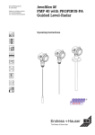
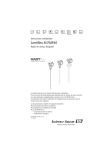
Brief operating instructions
Levelflex M FMP 40 with Foundation Fieldbus
Brief operating instructions
KA 189F/00/a2/03.02
52012501
000
measured value
-
+
Contrast:
+
or
+
E
E
Group
selection
-
E
+
002
tank
properties
003
medium
property
004
process
cond.
01
safety settings
- standard
- aluminium tank
- plastic tank
- bypass/pipe
- coax-probe
- concrete
wall
- unknown
- 1.4 … 1.6
- 1.6 … 1.9
- 1.9 … 2.5
- 2.5 … 4
-4…7
->7
input E
input F
D and L are
- standard
(see sketch) (see sketch) displayed
- fast
change
- slow
change
- test: no filter
03
length
adjustment
05
extended calibr.
030
end of
probe
- free
- tie down
isolated
- tie down
gnd.
09
display
092
language
0E
envelope curve
09B
recording
curve
- envel. curve
- substracted signal - single curve
- cyclic
- mapping
0A3
0A1
0A0
reset
previous
present
error
error
04
linearisation
0A
diagnostics
0C
system
parameters
008
dist./
meas value
E
00
basic setup
+
-
Levelflex M - Brief operating instructions
031
probe
length
… …
005
empty
calibr.
006
full
calibr.
008
dist./
meas value
051
check
distance
052
range of
mapping
053
start
mapping
confirm
suggestion
or specify
range
reference point of
033
034
measurement
probe
determine
length
length
UB
If shortened
threaded
please enter probe length here.
connection
¾ or 1 ½ BSP
(G ¾ or G 1½)
¾ or 1½ NPT:
reference point of
measurement
LB
032
probe
09A
plot settings
E
F
LN
min.level
0A4
unlock
parameter
… …
UB = upper blocking distance
LB = lower bllocking distance
LN = probe lenght
(333 = reset customer parameters) = 100: unlocked
≠ 100: locked
52012501
Note!
This operating manual explains the installation and initial start-up for the level transmitter measuring device. All
functions that are required for a typical measuring task are taken into account here.
In addition, the Levelflex M provides many other functions that are not included in this operating manual, such as
optimising the measuring point and converting the measured values.
An overview of all device functions can be found on page 94.
The operating manual BA 245F/00/en provides an extensive description of all device functions – Description of the
device functions for Levelflex M, which can also be found on the enclosed CD-ROM.
2
Endress+Hauser
Levelflex M FMP 40 with Foundation Fieldbus
Table of contents
Table of contents
1
Safety instructions . . . . . . . . . . . . . . . . . 4
6
Commissioning . . . . . . . . . . . . . . . . . . . 56
1.1
1.2
1.3
1.4
Designated use . . . . . . . . . . . . . . . . . . . . . . . .
Installation, commissioning and operation . . .
Operational safety . . . . . . . . . . . . . . . . . . . . . .
Notes on safety conventions and symbols . . .
2
Identification . . . . . . . . . . . . . . . . . . . . . . 6
2.1
2.2
2.3
2.4
Device designation . . . . . . . . . . . . . . . . . . . . .
Scope of delivery . . . . . . . . . . . . . . . . . . . . . . .
Certificates and approvals . . . . . . . . . . . . . . . .
Registered trademarks . . . . . . . . . . . . . . . . . .
6.1
6.2
6.3
6.4
6.5
6.6
6.7
6.8
Function check . . . . . . . . . . . . . . . . . . . . . . . . 56
Switching on the measuring device . . . . . . . . 56
Basic Setup . . . . . . . . . . . . . . . . . . . . . . . . . . . 57
Basic Setup with the VU 331 . . . . . . . . . . . . . 59
Blocking distnace . . . . . . . . . . . . . . . . . . . . . . 67
Envelope curve with VU 331 . . . . . . . . . . . . . . 68
Function "envelope curve display" (0E3) . . . . 69
Basic Setup with the ToF Tool . . . . . . . . . . . . 71
7
Maintenance . . . . . . . . . . . . . . . . . . . . . . 76
3
Mounting . . . . . . . . . . . . . . . . . . . . . . . . . 10
8
Accessories . . . . . . . . . . . . . . . . . . . . . . . 77
3.1
3.2
3.3
3.4
3.5
Quick installation guide . . . . . . . . . . . . . . . . .
Incoming acceptance, transport, storage . . .
Installation Conditions . . . . . . . . . . . . . . . . . .
Installation . . . . . . . . . . . . . . . . . . . . . . . . . . .
Post-installation check . . . . . . . . . . . . . . . . . .
9
Trouble-shooting . . . . . . . . . . . . . . . . . 81
4
Wiring . . . . . . . . . . . . . . . . . . . . . . . . . . . . . 29
4.1
4.2
4.3
4.4
4.5
Quick wiring guide . . . . . . . . . . . . . . . . . . . . .
Cable specifications Foundation Fieldbus . .
Connection data . . . . . . . . . . . . . . . . . . . . . .
Recommended connection . . . . . . . . . . . . . .
Post-connection check . . . . . . . . . . . . . . . . .
9.1
9.2
9.3
9.4
9.5
9.6
9.7
9.8
Trouble-shooting instructions . . . . . . . . . . . . . 81
System error messages . . . . . . . . . . . . . . . . . 82
Application errors . . . . . . . . . . . . . . . . . . . . . . 84
Spare parts . . . . . . . . . . . . . . . . . . . . . . . . . . . 86
Return . . . . . . . . . . . . . . . . . . . . . . . . . . . . . . . 88
Disposal . . . . . . . . . . . . . . . . . . . . . . . . . . . . . 88
Software history . . . . . . . . . . . . . . . . . . . . . . . 88
Contact addresses of Endress+Hauser . . . . . 88
10
Technical data . . . . . . . . . . . . . . . . . . . . 89
4
4
4
5
6
9
9
9
10
11
12
13
28
29
30
30
31
31
10.1 Technical data at a glance . . . . . . . . . . . . . . . 89
5
Operation . . . . . . . . . . . . . . . . . . . . . . . . . 32
5.1
5.2
5.3
5.4
5.5
Quick operation guide . . . . . . . . . . . . . . . . . .
Display and operating elements . . . . . . . . . .
Local operation . . . . . . . . . . . . . . . . . . . . . . .
Display and acknowledging error messages
Foundation Fieldbus communication . . . . . . .
32
34
36
39
40
11
Appendix . . . . . . . . . . . . . . . . . . . . . . . . . 94
11.1 Operating menu HART (Display modul),
ToF Tool . . . . . . . . . . . . . . . . . . . . . . . . . . . . . 94
11.2 Operating matrix Foundation Fieldbus/
Commuwin II . . . . . . . . . . . . . . . . . . . . . . . . . . 96
11.3 Description of functions . . . . . . . . . . . . . . . . . 97
11.4 Function and system design . . . . . . . . . . . . . . 98
Index . . . . . . . . . . . . . . . . . . . . . . . . . . . . . . . . . 103
Endress+Hauser
3
1 Safety instructions
Levelflex M FMP 40 with Foundation Fieldbus
1
Safety instructions
1.1
Designated use
The Levelflex M FMP 40 is a compact level transmitter for the continuous measurement
of solids and liquids, measuring prinziple: Guided Level Radar /
TDR: Time Domain Reflectometry).
1.2
Installation, commissioning and operation
The Levelflex M has been designed to operate safely in accordance with current
technical, safety and EU standards. If installed incorrectly or used for applications for
which it is not intended, however, it is possible that application-related dangers may
arise, e.g. product overflow due to incorrect installation or calibration. For this reason,
the instrument must be installed, connected, operated and maintained according to the
instructions in this manual: personnel must be authorised and suitably qualified. The
manual must have been read and understood, and the instructions followed.
Modifications and repairs to the device are permissible only when they are expressly
approved in the manual.
1.3
Operational safety
Hazardous areas
Measuring systems for use in hazardous environments are accompanied by separate
"Ex documentation", which is an integral part of this Operating Manual. Strict
compliance with the installation instructions and ratings as stated in this supplementary
documentation is mandatory.
• Ensure that all personnel are suitably qualified.
• Observe the specifications in the certificate as well as national and local regulations.
4
Endress+Hauser
Levelflex M FMP 40 with Foundation Fieldbus
1.4
1 Safety instructions
Notes on safety conventions and symbols
In order to highlight safety-relevant or alternative operating procedures in the manual,
the following conventions have been used, each indicated by a corresponding symbol
in the margin.
Safety conventions
Explosion protection
Electrical symbols
Endress+Hauser
Symbol
Meaning
#
Warning!
A warning highlights actions or procedures which, if not performed correctly,
will lead to personal injury, a safety hazard or destruction of the instrument
"
Caution!
Caution highlights actions or procedures which, if not performed correctly, may
lead to personal injury or incorrect functioning of the instrument
!
Note!
A note highlights actions or procedures which, if not performed correctly, may
indirectly affect operation or may lead to an instrument response which is not
planned
0
Device certified for use in explosion hazardous area
If the Levelflex has this symbol embossed on its name plate it can be installed
in an explosion hazardous area
-
Explosion hazardous area
Symbol used in drawings to indicate explosion hazardous areas.
– Devices located in and wiring entering areas with the designation
“explosion hazardous areas” must conform with the stated type of
protection
.
Safe area (non-explosion hazardous area)
Symbol used in drawings to indicate, if necessary, non-explosion hazardous
areas.
– Devices located in safe areas still require a certificate if their outputs run into
explosion hazardous areas.
%
Direct voltage
A terminal to which or from which a direct current or voltage may be applied or
supplied
&
Alternating voltage
A terminal to which or from which an alternating (sine-wave) current or voltage
may be applied or supplied
)
Grounded terminal
A grounded terminal, which as far as the operator is concerned, is already
grounded by means of an earth grounding system
*
Protective grounding (earth) terminal
A terminal which must be connected to earth ground prior to making any other
connection to the equipment
+
Equipotential connection (earth bonding)
A connection made to the plant grounding system which may be of type e.g.
neutral star or equipotential line according to national or company practice
5
2 Identification
Levelflex M FMP 40 with Foundation Fieldbus
2
Identification
2.1
Device designation
2.1.1
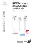
Nameplate
The following technical data are given on the instrument nameplate:
Designation according to Directive 94/9/EC
and designation of protection
Order No
(see Order Information)
ENDRESS+HAUSER
LEVELFLEX-M
Serial number
Made in Germany
D-79689 Maulburg
Order Code:
Ser.-No.:
LN=
Communication
variant and
supply voltage
IP68 / NEMA 6P
PN=
Profibus PA
Foundation Fieldbus
90 … 253 V AC 3,5VA
10,5 … 32 V DC 1W
16 … 3
V DC 0,8W
4 … 20 mA HART
TA > 70°C : t >85°C
2-wire
4-wire
if modification
X = see sep. label
Dat./Insp.:
Patents
D01301-A
Reference to additional
safety-relevant documentation
Fig. 1
2.1.2
Information on the nameplate of the Levelflex M FMP 40 (example)
Ordering structure
Ordering structure Levelflex M FMP 40
10
20
FMP 40-
Certificates
A For non-hazardous areas
M FM
DIP, Class II, Division 1, Group E-G N.I.
N CSA
General Purpose
P CSA
DIP, Class II, Division 1, Group G+coal dust, N.I.
S FM
IS - Class I/II/III, Division 1, Group A-G N.I.
T FM
XP - Class I/II/III, Division 1, Group A-G
U CSA
IS - Class I/II/III, Division 1, Group A-D, G+coal dust, N.I.
V CSA
XP - Class I/II/III, Division 1, Group A-D, G+coal dust, N.I.
1 ATEX II 1/2 G
EEx ia IIC T6
2 ATEX II 1/2 D
Alu cover, dust Ex
3 ATEX II 2 G
EEx em [ia] IIC T6
4 ATEX II 1/3 D
transp. cover, dust Ex
5 ATEX II 1/2 G, II 1/3 D
EEx ia IIC T6
Y Special version
Probe version, material 1)
Type / application
A 4 mm rope probe, predominantly bulk solids
B 6 mm rope probe, solids
K One rod probe 16 mm, predominantly liquids
L Coax probe, liquids
P Rod probe 6 mm, liquids
Y Special version
Material
316
316
316L
316L
316L
Product designation (part 1)
1) Rod and coaxial probes are also available in Alloy C22. In this case the probe rod is
fixed to the instrument and can not be dismantled.
6
Endress+Hauser
Levelflex M FMP 40 with Foundation Fieldbus
30
2 Identification
Probe length
Rope probes: 1000 mm...35000 mm / 40 in...1378 in
A mm, 4 mm rope, 316
B mm, 6 mm rope, 316
C in, 1/6" rope, 316
D in, 1/4" rope, 316
K
L
M
N
Rod probes: min. 300 mm...4000 mm / 12 in...157 in
mm, rod 16 mm, 316L
mm, coax probe, 316L
in (0,1 in), rod 16 mm, 316L
in (0,1 in), coax probe, 316L
Rod probes: min. 300 mm...2000 mm / 12 in...80 in
P mm, rod 6 mm, 316L
R in (0,1 in), rod 6 mm, 316L
Y Special version
40
50
Sealing
2 FKM O-ring (e.g. Viton)
3 EPDM O-ring
4 FFKM O-ring (e.g. Kalrez)
9 Special version
Process connection, material
Threaded connection Material
CNJ ¾" NPT
316L
CRJ G ¾", ISO 228
1.4435
GNJ 1½" NPT
316L
GRJ G 1½", ISO 228
1.4435
CFJ
CGJ
CMJ
CQJ
CTJ
CWJ
CXJ
ACJ
ADJ
AEJ
AFJ
ALJ
AMJ
APJ
AQJ
AWJ
A3J
KDJ
KEJ
KLJ
KPJ
YY9
60
FMP 40-
Endress+Hauser
temperature -30° C...+150° C
temperature -40° C...+120° C
temperature -5° C...+150° C
Flange Dia/Pressure
DN40 PN40
DN50 PN40
DN80 PN16
DN100 PN16
DN100 PN40
DN150 PN16
DN200 PN16
1½"/150 lbs
1½"/300 lbs
2"/150 lbs
2"/300 lbs
3"/150 lbs
3"/300 lbs
4"/150 lbs
4"/300 lbs
6"/150 lbs
8"/150 lbs
10 K 40A
10 K 50A
10 K 80A
10 K 100A
Special version
Standard
DIN 2526 Form C
DIN 2526 Form C
DIN 2526 Form C
DIN 2526 Form C
DIN 2526 Form C
DIN 2526 Form C
DIN 2526 Form C
ANSI B16.5
ANSI B16.5
ANSI B16.5
ANSI B16.5
ANSI B16.5
ANSI B16.5
ANSI B16.5
ANSI B16.5
ANSI B16.5
ANSI B16.5
JIS B2210
JIS B2210
JIS B2210
JIS B2210
Material
316L
316L
316L
316L
316L
316L
316L
316L
316L
316L
316L
316L
316L
316L
316L
316L
316L
316L
316L
316L
316L
Electronic insert / Communication
B 2-wire, 4…20 mA HART
D 2-wire, PROFIBUS-PA
F 2-wire, Foundation Fieldbus
G 4-wire, 90...250 VAC, 4...20 mA HART
H 4-wire, 10,5...32 VDC, 4...20 mA HART
Y Special version
Product designation (part 2)
7
2 Identification
Levelflex M FMP 40 with Foundation Fieldbus
70
Display
1 without display
2 with display VU 331 incl. on-side operation
9 Special version
80
Remote electronic
1 Standard compact device
2 distance sleeve 400 mm for electronic
3 remote electronic, 3 m cable
9 Special version
90
Housing and cable gland / entry
housing
A aluminium F12-housing,
coated, IP68
B aluminium F12-housing,
coated, IP68
C aluminium F12-housing,
coated, IP68
D aluminium F12-housing,
coated, IP68
E aluminium F12-housing,
coated, IP68
G aluminium T12-housing,
coated, IP68
H aluminium T12-housing,
coated, IP68
J aluminium T12-housing,
coated, IP68
K aluminium T12-housing,
coated, IP68
L aluminium T12-housing,
coated, IP68
9 Special version
100
FMP 40-
cable gland/-entry
cable gland M20x1,5
cable entry G ½
cable entry ½ NPT
M12 PROFIBUS-PA plug
7/8" FF-plug
cable gland M20x1,5
cable entry G ½
cable entry ½ NPT
M12 PROFIBUS-PA plug
7/8" FF-plug
Additional options
A Additional options not selected
B 3.1.B material, wetted parts SS316Ti,
Inspection Certificate EN 10204, acc. specification 52005759
Y Special version
Complete product designation
⇓
Please enter probe length in mm or inch / 0.1 inch
mm
inch / 0.1 inch
probe length LN see page 12
8
Endress+Hauser
Levelflex M FMP 40 with Foundation Fieldbus
2.2
"
2 Identification
Scope of delivery
Caution!
It is essential to follow the instructions concerning the unpacking, transport and storage
of measuring instruments given in the chapter »Incoming acceptance, transport, storage« on page 11.
The scope of delivery consists of:
• Assembled instrument
• 2 ToF Tool CD-ROMs
– CD 1: ToF Tool Program
– CD 2: Device descriptions (device drivers) and documentation for all
Endress+Hauser devices which are operable using ToF Tool
• Accessories (s. Chapter 8)
Accompanying documentation:
• Short manual (basic equalisation/troubleshooting): housed in the instrument
• Operating manual (this manual)
• Operating manual: Description of the instrument functions
• Approval documentation: if this is not included in the operating manual.
2.3
Certificates and approvals
CE mark, declaration of conformity
The instrument is designed to meet state-of-the-art safety requirements, has been
tested and left the factory in a condition in which it is safe to operate. The instrument
complies with the applicable standards and regulations in accordance with EN 61010
"Protection Measures for Electrical Equipment for Measurement, Control, Regulation
and Laboratory Procedures". The instrument described in this manual thus complies
with the statutory requirements of the EG directives. Endress+Hauser confirms the
successful testing of the instrument by affixing to it the CE mark.
2.4
Registered trademarks
KALREZ ®, VITON ®, TEFLON ®
Registered trademark of the company E.I. Du Pont de Nemours & Co., Wilmington, USA
TRI-CLAMP ®
Registered trademark of the company Ladish & Co., Inc., Kenosha, USA
HART ®
Registered trademark of HART Communication Foundation, Austin, USA
ToF ®
Registered trademark of the company Endress+Hauser GmbH+Co. KG, Maulburg,
Germany
PulseMaster ®
Registered trademark of the company Endress+Hauser GmbH+Co. KG, Maulburg,
Germany
FoundationTM Fieldbus
Registered trademark of Fieldbus Foundation Austin, Texas, USA
Endress+Hauser
9
3 Mounting
Levelflex M FMP 40 with Foundation Fieldbus
3
Mounting
3.1
Quick installation guide
F12 or T12 housing
Turn housing
The housing can be turned 350°
in order to simplify access to the
display and the terminal compartment
1½"
F12 housing
Caution!
Use only the
threaded boss ???
2
AF 60
60
3
max. torque
20 Nm
1
F12 or T12 housing
¾"
50
AF 50
max. torque
5 Nm
10
Endress+Hauser
Levelflex M FMP 40 with Foundation Fieldbus
3.2
Incoming acceptance, transport, storage
3.2.1
Incoming acceptance
3 Mounting
Check the packing and contents for any signs of damage.
Check the shipment, make sure nothing is missing and that the scope of supply
matches your order.
3.2.2
"
Transport
Caution!
Follow the safety instructions and transport conditions for instruments of more than
18 kg. Do not lift the measuring instrument by its probe rod in order to transport it.
3.2.3
Storage
Pack the measuring instrument so that is protected against impacts for storage and
transport. The original packing material provides the optimum protection for this.
The permissible storage temperature is -40 °C…+80 °C.
Endress+Hauser
11
3 Mounting
Levelflex M FMP 40 with Foundation Fieldbus
3.3
Installation Conditions
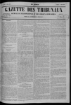
3.3.1
Dimensions
T12 housing
Ø 129
68
ENDRESS+HAUSER
Levelflex-M
94
65
78
ENDRESS+HAUSER
Levelflex-M
85
162
78
150
65
Ø 129
F12 housing
ca. 86
85
option:
remote electronic
123
88
option:
distance sleeve
88
112
Ø 60,3
270...310
2765
400
4 x Ø 8,5
Ø 76
Threaded connection
G 1 ½ (1 ½BSP)
or 1 ½ NPT
SW 60
110
68
Flange DN 40…200
or equivalent
Ø 60
110
Threaded connection
G ¾ (¾ BSP)
or ¾ NPT
SW 50
Ø 76
Ø 67,8
25
measurement
25
reference point of
Probe rods in Alloy C22
consist of 1 piece
(can not be dismantled)
rod probe
rope:
Ø 4 mm/0.16”
or
Ø 6 mm/0.24”
150
coax probe
probe length LN
rope probe
internal thread:
M14 on 4 mm/0.16” rope
M20 on 6 mm/0.24” rope
Ø 6/0.24” (on ¾” thread)
Ø 16/0.63” (on 1½” thread
or flange)
Ø 21,3/0.84” (on ¾” thread)
Ø 42,4/1.67” (on 1½” thread
or flange)
Ø 22/0.87” (on 4 mm/0.16” rope)
Ø 30/1.18” (on 6 mm/0.24” rope)
Fig. 2
12
Dimensions Levelflex M FMP 40
Endress+Hauser
Levelflex M FMP 40 with Foundation Fieldbus
3.4
Installation
3.4.1
Mounting kit
3 Mounting
In addition to the tool needed for flange mounting, you will require the following tool:
• 4 mm Allen wrench for turning the housing.
Shortening probes
Rod and rope probes can be easily shortened. This is necessary if the distance to the
container floor or outlet cone is less than 150 mm in the case of a rope probe, or less
than 100 mm in the case of a rod probe or less than 50 mm in the case of a coax probe.
Shortening rod probes
The rods of a rod probe are shortened by sawing or separating at the bottom end.
M4
secured with
Loctite 243
torque
4 mm cable = 5 Nm
6 mm cable =15 Nm
60 / 80 mm
Shortening rope probes
• Remove ballast weight:
– The weight is fixed to the probe rope
with 3 Allen setscrews (M4, Allen key
AF3). The screws are secured with
Loctite. This may first have to be made
plastic with a hot air apparatus.
• Remove released rope from the weight
• Measure off new rope length
• Wrap adhesive tape around the rope at
the point to be shortened to prevent it
from fanning out.
• Saw off the rope at a right angle or cut it
off with a bolt cutter.
• Insert the rope completely into the
weight,
– thin rope (4 mm) 60 mm deep,
– thick rope(6 mm) 80 mm deep
The weight is then refixed to the rope:
• Reapply screw locking fluid (we recommend Loctite type 243) to the setscrews
and screw into place.
• When doing so, observe the following
torques:
– For 6 mm rope: 15 Nm
– For 4 mm rope: 5 Nm
Shortening coax probes
Coax probes can be shortened max. 80 mm from the end. They have centering units
inside which fix the rod centrally in the pipe. The centerings are held with borders on the
rod. Shortening is possible up to approx. 10 mm below the centering.
Endress+Hauser
13
3 Mounting
Levelflex M FMP 40 with Foundation Fieldbus
3.4.2
Engineering hints for level measurement in bulk solids and
fluids
The following installation instructions apply for rope and rod probes for measurement in
bulk solids and fluids.
Coax probes are suitable purely for measurement in fluids. They function practically
independent of all installation conditions and can, therefore, be installed as desired.
• Temperature conditions must be met (see page 90).
• It is recommended that a protective cover (1) is used, in order to protect the
transmitter against direct sunlight or rain (see »Accessories« on page 77.).
Mounting location
• Do not mount rod or rope probes in the
filling curtain (3)
• Mount rod and rope probes away from
the wall (B) at such a distance that, in the
event of build-up on the wall, there is still
a minimum distance of 100 mm between
the probe and the build-up.
• Mount rod and rope probes as far away
as possible from installed fittings.
"Mapping " must be carried out during
commissioning in the event of distances
< 300 mm.
• When installing rod and rope probes in
plastic containers, the minimum
distance of
300 mm also applies to metallic parts
outside the container.
• Rod and rope probes may not, at times,
contact metallic container walls or floors.
• In metal containers, do not install rod
and rope probes exactly in the centre
(2).
• Minimum distance of probe end to the
container floor (C):
– Rope probe: 150 mm
– Rod probe: 100 mm
– Coax probe: 50 mm
• When installing outdoors, it is
recommended that you use a protective
cover (1) see »Accessories« on
page 77..
14
1
2
3
B
C
Endress+Hauser
Levelflex M FMP 40 with Foundation Fieldbus
3 Mounting
Other installations
• Select the mounting location such that
the distance to internals (5) (e.g. limit
switch, struts) > is 300 mm over the
entire length of the probe, also during
operation.
• Probe must within the measuring span
not touch any internals during operation.
If necessary: when using rope probes
the probe end (4) may be fixed to ensure
that (see page 23)!.
5
Optimization options
• Interference echo suppression:
Measurement can be optimised by
electronically tuning out interference
echoes.
4
Minimum distance B of the probe to the container wall:
Wall
min. distance B
Metal
100 mm for smooth walls
Plastic
100 mm, min. 300 mm to metallic components outside of the tank
Concrete
0.5 m/20", otherwise the max. possible measuring range is reduced
Distance to protruding internals min. 300 mm.
Endress+Hauser
15
3 Mounting
Levelflex M FMP 40 with Foundation Fieldbus
Standard installation
• Probes are mounted to the process connection with threaded connections or flanges
and are usually also secured with these. If during this installation there is the danger
that the probe end moves so much that it touches the tank floor or cone at times, the
probe must, if necessary, be shortened and fixed down. The easiest way to fix the rope
probes is to screw them to the internal thread on the lower end of the weight. Thread
size, see page 23.
• The ideal installation is mounting in a screwed joint / screw-in sleeve which is internally
flush with the container ceiling.
• If installation takes place in a nozzle, the nozzle should be 50 ... 150 mm in diameter
and should not be more than 150 mm high. Installation adapters are available for other
dimensions, see »Accessories« on page 77.
installation with welding boss
1½" or ¾"
installation in nozzle
≤ 150 mm
(≤ 4")
diameter nozzle:
≤ DN150 (≤ 6”)
Probe length
• The measuring range is directly dependent on the probe length. If the probe is not
fixed at the bottom end, the following distances to the container floor must be
observed:
– Rope probe: 150 mm
– Rod probe: 100 mm
– Coax probe: 30 mm
It is better to order probes too long than too short since it is possible to shorten the
probe if necessary.
16
Endress+Hauser
Levelflex M FMP 40 with Foundation Fieldbus
3.4.3
3 Mounting
Special notes for bulk solids
• In the case of bulk solids, as great a
distance as possible from the filling
curtain is especially important to avoid
wear.
• In concrete silos, a large distance (B)
should be observed between the probe
and the concrete wall, if possible >= 1m,
but at least 0.5m
B
Installation in concrete silos
Installation, for example, into a thick concrete ceiling should be made flush with the
lower edge. Alternatively, the probe can also be installed into a pipe that must not
protrude over the lower edge of the silo ceiling. Installation suggestions see diagram.
≥ 100 mm
≥ 100 mm
metal
Ø 80...150 mm
Extension rod /
Centering
(see accessories)
Endress+Hauser
17
3 Mounting
Levelflex M FMP 40 with Foundation Fieldbus
3.4.4
Installation in bulk solid silos
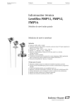
Tensile load
Bulk solids exert tensile forces on rope probes whose height increases with::
• the length of the probe, i.e. max. cover,
• the bulk density of the product,
• the silo diameter and
• the diameter of the probe rope
The following diagrams show typical loads for frequently occurring bulk solids as
reference values. The calculation is performed for the following conditions:
• Suspended probe (probe end not fixed at the bottom)
• Free-flowing bulk solid, i.e. mass flow. A calculation for core flow is not possible.
In the event of collapsing cornices, considerably higher loads can occur.
• The specification for tensile forces contains the safety factor 2, which compensates
for the normal fluctuation range in pourable bulk solids.
18
35
16
30
40
25
20
30
15
20
10
12
polyethylene pellets
smooth metallic walls
silo diameter 12 m
silo diameter 9 m
silo diameter 6 m
silo diameter 3 m
14
pulling force, 6 mm rope [kN]
11
10
9
8
12
7
10
6
8
5
4
6
3
4
10
2
5
0
0
5
10
15
20
25
30
2
0
35
1
0
0
5
10
level [m]
60
24
25
30
0
35
50
20
16
14
20
12
15
10
8
10
6
4
5
pulling force, 6 mm rope [kN]
18
25
40
cement
smooth metallic walls
silo diameter 12 m
silo diameter 9 m
silo diameter 6 m
silo diameter 3 m
22
pulling force, 4 mm rope [kN]
pulling force, 6 mm rope [kN]
30
20
level [m]
wheat
smooth metallic walls
silo diameter 12 m
silo diameter 9 m
silo diameter 6 m
silo diameter 3 m
35
15
35
30
40
25
20
30
15
20
10
pulling force, 4 mm rope [kN]
pulling force, 6 mm rope [kN]
50
40
pulling force, 4 mm rope [kN]
silica sand
smooth metallic walls
silo diameter 12 m
silo diameter 9 m
silo diameter 6 m
silo diameter 3 m
pulling force, 4 mm rope [kN]
60
10
5
2
0
0
5
10
15
20
level [m]
18
25
30
0
35
0
0
5
10
15
20
25
30
0
35
level [m]
Endress+Hauser
Levelflex M FMP 40 with Foundation Fieldbus
3 Mounting
Since the tensile forces are also heavily dependent on the viscosity of the product, a
higher safety factor is necessary for highly viscous products and if there is a risk of
cornice build-up.
In critical cases it is better to use a 6 mm rope instead of a 4 mm one.
The same forces also act on the silo cover.
On a fixed rope, the tensile forces are definitely greater, but this can not be calculated.
Observe the tensile strength of the probes or ensure that the tensile strength of the
probes is not exceeded.
Options for reducing the tensile forces:
• Shorten the probe
• If the maximum tensile load is exceeded, check whether it would be possible to use
a non-contact ultrasonic device.
Endress+Hauser
19
3 Mounting
Levelflex M FMP 40 with Foundation Fieldbus
3.4.5
Installation in liquids tanks
• When installing in agitation units, check whether a no-contact process (ultrasonic or
radar) would be better suited, especially if the agitator generates large mechanical
loads on the probe.
• If Levelflex is, nevertheless, installed in tanks with agitators, it is better to use coax
probes which have a greater lateral loading capacity.
Standard installation
Using a coax probe offers great advantages when the viscosity of the product is < 500
cst and it is certain that the product does not accumulate build-up:
• Greater reliability:
As of dielectric constant=1.4, measurement functions independently of all electrical
properties in all liquids.
• Internals in the tank and nozzle dimensions do not have any influence on
measurement.
• Higher lateral load-bearing capacity than rod probes.
• For higher viscosity a rod probe is recommended, or using a non-contact measuring
principle.
Installation in horizontal cylindrical
and standing tanks
• Use a coax or rod probe for measuring
ranges up to 4 m. For anything over this
or if there is too free cover space use a 4
mm rope probe.
• Installation and possible fixing as with
bulk solids.
• Any distance from wall, as long as
occasional contact is prevented.
• Do not mount a rod or rope probe (1)
exactly central when using metallic
containers. Central mounting doesn‘t
impair coax probe (2) performance.
• When installing in tanks with a lot of
internals or internals situated close to
the probe: Use a coax probe.
20
1
2
Endress+Hauser
Levelflex M FMP 40 with Foundation Fieldbus
3 Mounting
Installation in underground tanks
• Use coax probe for nozzles with large
diameters in order to avoid reflections at
the nozzle wall.
Measurement in corrosive fluids
For measurement in corrosive liquids, it is possible to install a rod probe in a closed
plastic pipe with a diameter of up to approx. 50 mm. When using plastic tanks it is also
possible to mount the probe on the outside of the tank (see Installation instructions on
Page 24). Levelflex measures the level through the plastic in both cases.
Installation in stilling well or bypass
• A rod probe can be used for pipe
diameters up to 150 mm, for diameters
above that the flange with horn adapter
recommended.
• When installing a rod probe into a
metallic pipe with internal diameter of up
to 150 mm, you have all the advantages
of a coax probe.
• Welded joints that protrude up to
approx.
5 mm/0.2" inwards do not influence
measurement.
Endress+Hauser
21
3 Mounting
Levelflex M FMP 40 with Foundation Fieldbus
Mounting Location
• Recommended distance B wallmounted rope probe: ~1/6...1/4 of the
container diameter (min. 100 mm/4",
concrete silos: min. 500 mm).
• Not central (2) in metallic tanks.
• Not in the filling curtain (3).
• Please order the probe length such that
it ends approx 30 mm above the floor of
the tank.
• Temperature conditions must be met.
• It is recommended that a protective
cover (1) be used, in order to protect the
transmitter against direct sunlight or
rain. Mounting and demounting are
carried out simply with a clamp (see
»Accessories« on page 77.).
1
2
3
B
Tank installations
• Select the mounting location such that
the distance to internals (4) (e.g. limit
switch, struts) is > 300 mm.
Optimization options
• Interference echo suppression:
Measurement can be optimised by
electronically tuning out interference
echoes.
• Bypass pipe and stilling well (only for
liquids): for viscosities of up to 500 cst, a
bypass pipe, stilling well or a coax probe
can be used to prevent interference.
22
4
Endress+Hauser
Levelflex M FMP 40 with Foundation Fieldbus
3.4.6
3 Mounting
Notes on special installation situations
Fixing rope probe
• The end of the probe needs to be
secured if the probe would otherwise
touch the silo wall, the cone or another
part, or the probe comes closer than 0.5
m to a concrete wall. This is what the
internal thread in the probe weight is
intended for:
– for 4 mm rope:M14
– for 6 mm rope:M20
• Preferably use the 6 mm rope probe due
to the higher tensile strength when fixing
a rope probe
• The fixing must be either reliably
grounded or reliably insulated (see
accessories). If it is not possible to
mount the probe weight with a safe
earthed connection, it can be secured
using an isolated eyelet, which is
available as an accessory
(see page 79).
• In order to prevent an extremely high
tensile load and the risk of rope crack,
the rope has to be slack. Make the rope
longer than the required measuring
range such that there is a sag in the
middle of the rope that is ≥ 1cm/m (1"/
100") of the rope length.
Reliable, earthed mounting
sag of the rope:
≥1cm/m of the rope
length
Reliable, isolated mounting
Mounting-kit isolated
(see accessories)
Mounting and
contact with a
bolt
4mm-rope: M14
6mm-rope: M20
Endress+Hauser
23
3 Mounting
Levelflex M FMP 40 with Foundation Fieldbus
Installation from the side
• If installation from above is not possible,
the Levelflex can also be mounted from
the side.
• In this case, always fix the rope probe
(see »Fixing rope probe« ).
• Support coax probe if the lateral loadbearing capacity is exceeded. Only fix
rod probes at the probe end.
• Connect rod probe metallically with the
container wall.
Installation in plastic containers
Please note that for rod and rope probes only with a metallic surface at the process
connection an optimal performance can be guaranteed.
When installing the probe in plastic silos, whose silo cover is also made of plastic or silos
with wood cover, the probes must either be mounted in a ≥ DN50 / 2" metallic flange, or
a metal sheet with diameter of ≥ 200 mm must be mounted under the screw-in piece.
metal sheet or metal flange
silo roof of plastic
or wood
metal sheet or metal flange
max. 20 mm
Wall thickness for GFK/PP
< 15 mm
• It is also possible to mount the probe externally on the tank wall for measuring in
Aqueous solutions. Measurement then takes place through the tank wall without
contacting the medium. If people are in the vicinity of the probe mounting location, a
plastic half pipe with a diameter of approx. 200 mm, or some other protective unit,
must be affixed externally to the probe to prevent any influences on the measurement.
• There must not be any metallic reinforcement rings secured to the tank.
• The wall thickness should be at Fibre-Glass Reinforced Plastic/PP < 15 mm.
• There must be no open space between the tank wall and the probe.
24
Endress+Hauser
Levelflex M FMP 40 with Foundation Fieldbus
3 Mounting
• If measuring externally, an automatic probe length determination and a two point
linearisation must be performed in order to compensate for the time-of-flight change
caused by the plastic wall.
Installation in nozzles > 150 mm high
If, when installing probes in nozzles
DN 40...250/1 ½"...10" with nozzle height
(HS) of > 150 mm/6", the probe could
touch the lower edge of the nozzle due to
moving materials in the container, we
recommend using an extension rod with or
without centering disk.
This accessory consists of the extension
rod corresponding to the nozzle height, on
which a centering disk is also mounted if
the nozzles are narrow or when working in
bulk solids. This component is delivered
separately from the device. Please order
the probe length correspondingly shorter.
For the exact length of the rod
see page 78.
Order codes for specific nozzle nominal
diameters and heights can be found on
Page 78.
Only use centering disks with small
diameters (DN 40 and DN 50) if there is no
significant build-up in the nozzle above
the disk.
DN50 (2")
DN80 (3")
DN150 (6")
DN200 (8")
DN250 (10")
HS
centering disk
at PPS - GF40
#
Not for ¾".
For rod probe on request.
Installation in DN 200/DN 8" and
DN 250/DN 10"nozzles
When installing the Levelflex in nozzles of
> 210 mm / 8", signals are generated by
reflections on the nozzle wall, which can
sometimes lead to faulty measurements in
the case of products with small dielectric
constants With nozzle diameters of 200
mm / 8" or 250 mm / 10", therefore, a
special flange with a “horn adaptor” must
be fitted.
Nozzles with nominal diameters greater
than DN 250 / 10" should be avoided.
204 mm
DN200 (8")
DN250 (10")
Endress+Hauser
25
3 Mounting
Levelflex M FMP 40 with Foundation Fieldbus
Installation in > DN 300/DN 12"
nozzles
If installation in > 300mm/12" nozzles is
unavoidable, installation must be carried
out in accordance with the sketch on the
right.
pipe
Ø 150 … 180
Approx. flush with
the lower edge of
the nozzle (± 50 mm).
3.4.7
plate
nozzle diameter
plate diameter
DN 300
280
> DN 400
> 350
Installation for difficult to access process connections
For tight spaces or temperatures above that in the graphic, the electronics housing can
be ordered with distance pipe or connecting cable (seperate housing).
400
Installation with distance pipe
• Follow installation instructions on
Page 14 ff..
• After mounting, the housing can be
turned 350°, in order make access to the
display and the connection
compartment easier.
• The max. measuring range is reduced to
34 m/1338".
Ø 60,3
Ø 67
26
Endress+Hauser
Levelflex M FMP 40 with Foundation Fieldbus
3 Mounting
Installation with separate housing
• Follow installation instructions on Page 14 ff..
• Mount housing on a wall or pipe as shown in the diagram.
65
78
150
ENDRESS+HAUSER
Levelflex M
150
Ø 129
wall
88
85
123
52
88
4 x Ø 8,5
ENDRESS+HAUSER
Levelflex M
pipe
150
78
Ø 129
65
2765
94
85
112
96
max. 80
min. 30
1)
52
Ø 76
94
The separate housing is designed for use at high environmental temperatures at the
mounting location of the sensor. The max. measuring range is reduced to 30 m/1181".
The version with separate housing consists of the probe, a connecting cable and the
housing. If they are ordered as a set, they are assembled on delivery.
1) The protective hose can not be dismantled at this point.
Endress+Hauser
27
3 Mounting
Levelflex M FMP 40 with Foundation Fieldbus
3.4.8
Turn housing
After mounting, the housing can be turned 350° in order to simplify access to the display
and the terminal compartment. Proceed as follows to turn the housing to the required
position:
• Undo the fixing screws (1)
• Turn the housing (2) in the required direction
• Tighten up the fixing screws (1).
F12 housing
2
1
allen key
4 mm/0.1”
3.5
Post-installation check
After the measuring instrument has been installed, perform the following checks:
• Is the measuring instrument damaged (visual check)?
• Does the measuring instrument correspond to the measuring point specifications
such as process temperature/pressure, ambient temperature, measuring range, etc.?
• Are the measuring point number and labeling correct (visual check)?
• Is the measuring instrument adequately protected against rain and direct sunlight
(see page 77 ff.)?
28
Endress+Hauser
Levelflex M FMP 40 with Foundation Fieldbus
4 Wiring
4
Wiring
4.1
Quick wiring guide
Wiring in F12 housing
"
Before connection please note the following:
●
Caution!
Foundation Fieldbus devices are marked on the nameplate (1).
The voltage is determined by the Foundation Fieldbus
standard and the desired safety concept. (e.g. FISCO).
●
Connect potential matching line to transmitter
ground terminal (7) before connecting up the device.
●
Tighten the locking screw (8):
It forms the connection between the antenna and the housing
earth potential.
1
ENDRESS+HAUSER
LEVELFLEX-M
Made in Germany
D-79689 Maulburg
Order Code:
Ser.-No.:
LN=
IP68 / NEMA 6P
PN=
Profibus PA
Foundation Fieldbus
90 … 253 V AC 1VA
10,5 … 32 V DC 1W
16 … 3
V DC 0,8W
4 … 20 mA HART
TA > 70°C : t >85°C
2-wire
4-wire
if modification
X = see sep. label
Dat./Insp.:
Patents
D01301-A
When you use the measuring system in hazardous areas, make sure you comply with
national standards and the specifications in the safety instructions (XA’s).
Make sure you use the specific cable gland.
-
On devices supplied with a certificate, the explosion protection
is designed as follows:
●
Housing F12 - EEx ia:
Power supply must be intrinsically safe.
●
The electronics and the current output are galvanically
separated from the probe circuit.
2
7
8
Connect up the Levelflex M as follows:
-
●
Unscrew housing cover (2).
●
Remove any display (3) if fitted.
●
Remove cover plate from terminal compartment (4).
●
Pull out terminal module slightly using pulling loop.
●
Insert cable (5) through gland (6).
Use screened, twisted wire pair.
#
Unplug display connector!
3
EN
DR
ES
S+
US
HA
ER
Only ground screen conductor (7) on sensor side.
●
Make connection (see pin assignment).
●
Re-insert terminal module.
●
Tighten cable gland (6).
●
Tighten screws on cover plate (4).
●
Insert display if fitted.
●
Screw on housing cover (2).
(on dust-Ex torque ≈ 40 Nm).
6
4
5
7
1 2 3 4
1 2 3 4
plant
ground
Sealed terminal
compartment
FF+ FF-
Endress+Hauser
29
4 Wiring
Levelflex M FMP 40 with Foundation Fieldbus
Wiring with M12 connector
Before connection please note the following:
"
●
Caution!
ENDRESS+HAUSER
PROSONIC-M
Foundation Fieldbus devices are marked on the
nameplate (1). The voltage is determined by the
Foundation Fieldbus standard and the desired safety
concept (e.g. FISCO).
1
x
IP68 / NEMA 6P
Profibus PA
Foundation Fieldbus
90 … 253 V AC 1VA
10,5 … 36 V DC 1W
10,5 … 36 V DC 0,8W
4 … 20 mA HART
●
Made in Germany
D-79689 Maulburg
Order Code:
Ser.-No.:
Connect potential matching line to transmitter earth
terminal (4) before connecting up the device.
TA > 70°C : t >85°C
2-wire
4-wire
if modification
X = see sep. label
Dat./Insp.:
Patents
D01345-A
When you use the measuring system in hazardous areas, make sure you comply with
national standards and the specifications in the safety instructions (XA’s).
-
On devices supplied with a certificate, the explosion protection
is designed as follows:
●
Housing F12 - EEx ia:
Power supply must be intrinsically safe (e.g. FISCO).
●
The electronics and the current output are galvanically
separated from the antenna circuit.
3
2
The Levelflex M is connected as follows:
4.2
●
Insert plug (2) into bushing (3).
●
Screw firmly
●
Ground the device according to the desired safety concept.
4
Cable specifications Foundation Fieldbus
Twisted, shielded pairs must be used. The cable specifications can be taken from the
FF specification or IEC 61158-2. The following have been found suitable:
Non-Ex-area:
• Siemens 6XV1 830-5BH10,
• Belden 3076F,
• Kerpen CEL-PE/OSCR/PVC/FRLA FB-02YS(ST)YFL.
Ex-area:
• Siemens 6XV1 830-5AH10,
• Belden 3076F,
• Kerpen CEL-PE/OSCR/PVC/FRLA FB-02YS(ST)YFL
4.3
Connection data
Supply voltage
The following values are the voltages across the terminals directly at the instrument:
Type
Terminal voltage
minimum
maximum
standard
9V
32 V
EEx ia (FISCO model)
9V
17.5 V
EEx ia (Entity concept)
9V
24 V
Current consumption
approx 15 mA for the range of voltages given above
30
Endress+Hauser
Levelflex M FMP 40 with Foundation Fieldbus
4.4
4 Wiring
Recommended connection
F12 housing
1
For maximum EMC protection please observe the following points:
• The external ground terminal (1) on the transmitter must be connected to ground.
• The continuity of the cable screening between tapping points must be ensured.
• If potential equalisation is present between the individual grounding points, ground
the screening at each cable end or connect it to the device housing (as short as possible).
• If there are large differences in potential between grounding points, the grounding
should run via a capacitor that is suitable for high frequency use (e.g. ceramic 10 nF/
250 V~).
"
Caution!
Applications, which are subject to the explosion prevention, permit only under special
conditions the repeated grounding of the protective screen , see to EN 60 079-14..
4.5
Post-connection check
After wiring the measuring instrument, perform the following checks:
• Is the terminal allocation correct (see page 29 ff. and page 30)?
• Is the cable gland tight?
• Is the Fieldbus connector screwed tight?
• Is the housing cover screwed tight?
• If auxiliary power is available:
Is the instrument ready for operation and does the liquid crystal display show any
value?
Endress+Hauser
31
5 Operation
Levelflex M FMP 40 with Foundation Fieldbus
5
Operation
5.1
Quick operation guide
ENDRESS + HAUSER
–
+
X
E
F
2x
X
O
basic setup
safety settings
F
X
X
tank shape
O
Standard
F
aluminium tank
>3 s
medium property
...
Return to
Group Selection
O
plastic tank
linearisation
bypass / pipe
extended calibr.
...
S
S
coax probe
concrete wall
S
...
Selection and configuration in Operation menu:
1.) Change from Measured Value Display to Group Selection by pressing F
2.) Press S or O to select the required Function Group (e.g.. "basic setup (00)") and confirm by pressing
F ➜ First function (e.g. "tank shape (002)") is selected.
Note!
The active selection is marked by a ✔ in front of the menu text.
3.) Activate Edit mode with O or S.
Selection menus:
a) Select the required Parameter in selected function (e.g. "tank shape (002)") with S or O.
b) F confirms selection ➜ ✔ appears in front of the selected parameter
c) F confirms the edited value ➜ system quits Edit mode
d) O / S (= X) interrupts selection ➜ system quits Edit mode
Typing in numerals and text:
a) Press O or S to edit the first character of the numeral / text (e.g. "empty calibr. (005)")
b) F positions the cursor at the next character ➜ continue with (a) until you have completed your input
c) if a symbol appears at the cursor, press F to accept the value entered
➜ system quits Edit mode
d) O / S (= X) interrupts the input, system quits Edit mode
4) Press F to select the next function (e.g. "medium property (003)")
5) Press O / S (= X) once ➜ return to previous function (e.g. "tank shape (002)")
Press O / S (= X) twice ➜ return to Group selection
6) Press O / S (= X) to return to Measured value display
32
Endress+Hauser
Levelflex M FMP 40 with Foundation Fieldbus
5.1.1
5 Operation
General structure of the operating menu
The operating menu is made up of two levels:
• Function groups (00, 01, 03, …, 0C, 0D):
The individual operating options of the instrument are split up roughly into different
function groups. The function groups that are available include, e.g.: "basic setup",
"safety settings", "profibus param.", "display", etc.
• Functions (001, 002, 003, …, 0D8, 0D9):
Each function group consists of one or more functions. The functions perform the
actual operation or parameterisation of the instrument. Numerical values can be
entered here and parameters can be selected and saved. The available functions of
the “basic setup (00)” function group include, e.g.:"tank properties" (002), "medium
property (003)", "process cond. (004)", "empty calibr. (005)", etc.
If, for example, the application of the instrument is to be changed, carry out the following
procedure:
1. Select the “basic setup (00)” function group.
2. Select the "tank properties" (002) function (where the existing tank shape is
selected).
5.1.2
Identifying the functions
For simple orientation within the function menus, for each function a position is shown
on the display.
The first two digits identify the function group:
• basic setup
00
• safety settings
01
• length adjustment 03
…
The third digit numbers the individual functions within the function group:
• basic setup
00
→
• tank properties
002
• medium property
003
• process cond.
004
…
• Here after the position is always given in brackets (e.g. "tank properties" (002)) after
the described function.
Endress+Hauser
33
5 Operation
Levelflex M FMP 40 with Foundation Fieldbus
5.2
Display and operating elements
END
RES
Order MICR
S+HA
OPIL
Ser.-NoCode:
OT USE
.:
R
II
IP
Maulburg
range
U 16...36
max.
4...20
20
m
V
mA DC
65
T
A >70°C
: t
>85°C
Made in Germany
Messbe
Measur reich
ing
LCD
(liquid crystal display)
ENDRESS + HAUSER
–
+
E
Symbols
Fig. 3
3 keys
Layout of the display and operating elements
5.2.1
Display
Liquid crystal display (LCD):
Four lines with 20 characters each. Display contrast adjustable through key
combination.
Headline
Position indicator
ENDRESS + HAUSER
Symbol
–
+
Main value
Unit
E
Selection list
Function groups -> Functions
HOME
X
F
O
S
Fig. 4
34
FG00
FG01
FG02
FG03
FG04
FG05
FG06
FG07
...
X
F
F
F000 F001 F002 F003 F004 ...
F
O
S
X
X
Help text
+21mV
Envelope
curve
0.00
2.305m
09C
10.00
Display
Endress+Hauser
Levelflex M FMP 40 with Foundation Fieldbus
5.2.2
5 Operation
Display symbols
The following table describes the symbols that appear on the liquid crystal display:
Symbols
Meaning
ALARM_SYMBOL
This alarm symbol appears when the instrument is in an alarm state. If the symbol flashes, this
indicates a warning.
LOCK_SYMBOL
This lock symbol appears when the instrument is locked,i.e. if no input is possible.
COM_SYMBOL
This communication symbol appears when a data transmission via e.g. HART, PFOFIBUS-PA
or Foundation Fieldbus is in progress.
Tab. 1
Meaning of Symbols
5.2.3
Key assignment
The operating elements are located inside the housing and are accessible for operation
by opening the lid of the housing.
Function of the keys
Key(s)
Meaning
O or V
Navigate upwards in the selection list
Edit numeric value within a function
S or W
Navigate downwards in the selection list
Edit numeric value within a function
X or Z
F or M
O and F
or
S and F
O and S and F
Tab. 2
Endress+Hauser
Navigate to the left within a function group
Navigate to the right within a function group, confirmation.
Contrast settings of the LCD
Hardware lock / unlock
After a hardware lock, an operation of the instrument via display or
communication is not possible!
The hardware can only be unlocked via the display. An unlock parameter must
be entered to do so.
Function of the keys
35
5 Operation
Levelflex M FMP 40 with Foundation Fieldbus
5.3
Local operation
5.3.1
Locking of the configuration mode
The Levelflex can be protected in two ways against unauthorised changing of instrument data, numerical values or factory settings:
"unlock parameter" (0A4):
A value <> 2457 (e.g. 2456) must be entered in "unlock parameter" (0A4) in the
"diagnostics" (0A) function group. The lock is shown on the display by the symbol
and can be released again either via the display or by communication.
Hardware lock:
The instrument is locked by pressing the O and S and F keys at the same time.
The lock is shown on the display by the symbol and can only be unlocked again
via the display by pressing the O and S and F keys at the same time again. It is not
possible to unlock the hardware by communication.
All parameters can de displayed even if the instrument is locked.
⇒
⇓
O and S and F press simultaneous
⇓
The LOCK_SYMBOL appears on the LCD.
36
Endress+Hauser
Levelflex M FMP 40 with Foundation Fieldbus
5.3.2
5 Operation
Unlocking of configuration mode
If an attempt is made to change parameters when the instrument is locked, the user is
automatically requested to unlock the instrument:
"unlock parameter" (0A4):
By entering the unlock parameter (on the display or via communication)
2457 = for PROFIBUS devices
the Levelflex is released for operation.
Hardware unlock:
After pressing the O and S and F keys at the same time, the user is asked to enter the
unlock parameter
2457 = for PROFIBUS devices.
⇒
O and S and F press simultaneous
⇓
Please enter unlock code and confirm with F.
⇓
"
Endress+Hauser
Caution!
Changing certain parameters such as all sensor characteristics, for example, influences
numerous functions of the entire measuring system, particularly measuring accuracy.
There is no need to change these parameters under normal circumstances and consequently, they are protected by a special code known only to the E+H service organization. Please contact Endress+Hauser if you have any questions.
37
5 Operation
Levelflex M FMP 40 with Foundation Fieldbus
5.3.3
"
Factory settings (Reset)
Caution!
A reset sets the instrument back to the factory settings. This can lead to an impairment
of the measurement. Generally, you should perform a basic setup again following a
reset.
A reset is only necessary:
• if the instrument no longer functions
• if the instrument must be moved from one measuring point to another
• if the instrument is being de-installed /put into storage/installed
⇒
User input ("reset" (0A3)):
• 33 333= reset of customer parameters
33 333 = reset customer parameters
This reset is recommended whenever an instrument with an unknown 'history' is to be
used in an application:
• The Levelflex is reset to the default values.
• The customer specific tank map is not deleted.
• The mapping can also be deleted in the "cust. tank map" (055) function of the
"extended calibr." (05) function group.
• A linearisation is switched to "linear" although the table values are retained. The table
can be reactivated in the "linearisation" (04) function group.
List of functions that are affected by a reset
•
•
•
•
•
•
•
•
•
•
•
•
•
•
•
•
•
tank properties (002)
medium cond. (003)
process proper. (004)
empty calibr. (005)
full calibr. (006)
output on alarm (010)
outp. echo loss (012)
ramp %span/min (013)
delay time (014)
safety distance (015)
in safety dist. (016)
overspill protection (018)
brocken probe det (019)
end of probe (030)
level/ullage (040)
linearisation (041)
customer unit (042)
•
•
•
•
•
•
•
•
•
•
•
•
•
•
•
•
max. scale (046)
diameter vessel (047)
check distance (051)
range of mapping (052)
start mapping (053)
delete mapping (055)
offset (057)
output damping (058)
language (092)
back to home (093)
format display (094)
no of decimals (095)
sep. character (096)
unlock parameter (0A4)
application par (0A8)
tag no (0C0)
A complete “basic setup" (00) must be activated.
38
Endress+Hauser
Levelflex M FMP 40 with Foundation Fieldbus
5.4
5 Operation
Display and acknowledging error messages
Type of error
Errors that occur during commissioning or measuring are displayed immediately on the
local display. If two or more system or process errors occur, the error with the highest
priority is the one shown on the display.
The measuring system distinguishes between two types of error:
• A (Alarm):
Instrument goes into a defined state (e.g. MAX 22 mA)
Indicated by a constant symbol.
(For a description of the codes, see table 9.2 on page 82)
• W (Warning):
Instrument continue measuring, error message is displayed.
Indicated by a flashing symbol.
(For a description of the codes, see table 9.2 on page 82)
• E (Alarm / Warning):
Configurable (e.g. loss of echo, level within the safety distance)
Indicated by a constant/flashing symbol.
(For a description of the codes, see table 9.2 on page 82)
⇒
Error messages
• Error messages appear as four lines of plain text on the display. In addition, a unique
error code is also output. A description of the error codes is given on page 82.
• The "diagnostics (0A)" function group can display current errors as well as the last
errors that occurred.
• If several current errors occur, use O or S to page through the error messages.
• The last occurring error can be deleted in the "diagnostics (0A)" function group
with the function"clear last error" (0A2).
Endress+Hauser
39
5 Operation
Levelflex M FMP 40 with Foundation Fieldbus
5.5
Foundation Fieldbus communication
5.5.1
Synopsis
There are two possibilities of connecting up a Foundation Fieldbus:
Direct connection to a FF/H1 card
Indirect connection via a linking device
40
Endress+Hauser
Levelflex M FMP 40 with Foundation Fieldbus
5.5.2
5 Operation
Hardware settings
A DIP-switch in the connection compartment of the Levelflex M controls allows the write
protection and simulation functions to be set via hardware.
• If "SIM" is switched off, the simulation function is not accesible in the configuration tool.
• If "WP" is switched on, parameter access is disabled.
END
RES
Order MICR
S+HA
OPIL
Ser.-NoCode:
OT USE
.:
R
II
IP
Maulburg
range
U 16...36
max.
4...20
20
m
V
mA DC
65
T
A >70°C
: t
>85°C
Made in Germany
Messbe
Measur reich
ing
default settings:
write protection OFF
simulation ON (i.e. simulation is
allowed in the configuration tool)
on
off
SIM WP
write protection
on
off
SIM WP
simulation
Device identification
Foundation Fieldbus identifies the device by its identification code and automatically
allocates an appropriate field address. There is no separate hardware switch for this
purpose.
Endress+Hauser
41
5 Operation
Levelflex M FMP 40 with Foundation Fieldbus
5.5.3
Network configuration
During the configuration of the FF network the device description (DD) of the Levelflex M
must be downloaded into the directory foreseen for it.
•
•
•
•
•
Start the interface configuration tool.
Configure the interface.
Call the DD download routine
Download the device descriptions (.ffo and .sym files) to the directory offered.
When the configuration is complete, close the tool and the FF stack (if open).
The Levelflex M device descriptions can be ordered direct from Endress+Hauser or
downloaded from our website www.endress.com. They contain all data necessary to
operate Endress+Hauser Foundation Fieldbus devices.
Example: Start-up using the NI-Fieldbus configurator
Start the bus configuration tool. After start-up, the tool shows the network configuration
in the form of an expandable tree. If the Levelflex M has been connected correctly, it can
now be identified:
E+H_LEVELFLEX_M_XXXXXXXX
A double click on the name reveals the device data:
PD_TAG
DEVICE_ID
NODE_ADDRESS
the physical name of the device
the unique device identifier
the fieldbus node to which the device is connected
(is automatically allocated by the Configurator)
The device ID is made up of the following components:
Device_ID = 452B481012-XXXXXXXX
whereby:
452B48
1012
XXXXXXXX
ID code for Endress+Hauser
ID code for Levelflex M
Device serial number, as printed on the nameplate
A right-hand mouse click on the name opens up a menu from which the PD_TAG and
NODE_ADDRESS can be changed
A click on the name expands the device tree to show the function blocks available for it:
E+H_LEVELFLEX_M_XXXXXXXX
RESOURCE_XXXXXX (RB2)
TRANSDUCER_XXXXXX (TBUL)
ANALOG_INPUT_1_XXXXXX (AI)
ANALOG_INPUT_2_XXXXXX (AI)
PID_XXXXXX(PID)
AR_XXXXXX (AR)
IS_XXXXXX (IS)
SC_XXXXXX (SC)
IT_XXXXXX (IT)
42
Endress+Hauser
Levelflex M FMP 40 with Foundation Fieldbus
5.5.4
5 Operation
Block model of the Levelflex M
The Levelflex M contains the follwoing blocks:
• Resource Block (RB2)
s. Operating Instructions BA 013S: "Foundation Fieldbus - Overview"
• Transducer Block (TB)
contains the parameters relevant to the measurement
• Analog-Input-Block 1 bzw. 2 (AI)
scale the signal of the Transducer Block and transmit them to the PLCS
• PID Block (PID)
s. Operating Instructions BA 013S: "Foundation Fieldbus - Overview"
• Arithmetic Block (AR)
s. Operating Instructions BA 013S: "Foundation Fieldbus - Overview"
• Input Selector Block (IS)
s. Operating Instructions BA 013S: "Foundation Fieldbus - Overview"
• Signal Characterizer Block (SC)
s. Operating Instructions BA 013S: "Foundation Fieldbus - Overview"
• Integrator Block (IT)
s. Operating Instructions BA 013S: "Foundation Fieldbus - Overview"
Default Block configuration
The input and output variables of the blocks can be interconnected by a network
configuration tool (e.g. NI-Fieldbus configurator). The figure below shows, how these
connections are set by default.
Sensor
signal evaluation
Display
Physical Block
parameters of the
physical unit, e.g.
tag No.
Transducer Block
Parameters that
Primary value
describe the
device (calibration, (main value)
linearisation etc.)
Secondary value
(distance)
Endress+Hauser
PID Block
Automation
functions
Analog Input Function Block 1
parameters that are important to
the process control system,
e.g. scaling, status
Analog Input Function Block 2
parameters that are important to
the process control system,
e.g. scaling, status
OUT
OUT
43
5 Operation
Levelflex M FMP 40 with Foundation Fieldbus
5.5.5
Resource block
The resource block contains the parameters used to describe physical resources of the
device. It has no linkable inputs or outputs.
Operation
The resource block is opened by a click on the resource line.
E+H_LEVELFLEX_M_XXXXXXXX
RESOURCE_XXXXXX (RB2)
TRANSDUCER_XXXXXX (TBUL)
ANALOG_INPUT_XXXXXX (AI)
If the NI-FBUS Configurator is being used, a series of file tabs appears on the screen.
The files can be opened to view and/or edit the parameters in the following table. A short
description of the parameter function appears on the side of the screen. A change in
the parameter is stored by pressing the WRITE CHANGES button when the block is out
of service. Press the READ ALL button to check the values stored in the device.
Parameters
Parameter
Description
TAG_DESC
User description of the intended application of the block.
MODE_BLK
Lists the actual, target, permitted and normal operating modes of the block.
– Target: changes the operating mode of the block
– Actual: indicates the current operating mode of the block
– Permitted: states which operating modes are allowed
– Normal: indicates the normal operating mode of the block
The possible operating modes of the resources block are:
– AUTO: the block is operating as normal
– OOS: the block is out of service.
If the resource block is out of service, then all blocks within the device (resource)
are forced into the same status.
RS_STATE
Indicates the state of the resource block application state machine
– On-line: block in AUTO mode
– Standby: block in OOS mode
WRITE_LOCK
Indicates the status of DIP-switch WP
– LOCKED: device data can be modified
– NOT LOCKED: device data can be modified
RESTART
Allows a manual restart:
– UNINITIALISED: no status
– RUN: normal operational status
– RESOURCE: resets the resource block parameters
– DEFAULTS: Resets all Foundation Fieldbus parameters within the
device, but not the manufacturer specific parameters.
– PROCESSOR: make a warm start of the processor
BLOCK_ERROR
Shows error status of software and hardware components
– Out-of-Service: the block is in OOS mode
– Simulation active: shows the setting of DIP-switch SIM
BLOCK_ALM
Shows any configuration, hardware, connection and system problems in the
block. The cause of the alert is to be seen in the subcode field.
The function of the resource block parameters not described here can can be taken
from the Foundation Fieldbus specification, see www.fieldbus.org.
44
Endress+Hauser
Levelflex M FMP 40 with Foundation Fieldbus
5.5.6
5 Operation
Transducer block
The transducer block contains the parameters required to calibrate the device. These
parameters can also be addressed by using the VU 331 display module. The calibration
of the device is described in Chapter 5.5.5 to Chapter 5.5.7
Operation
The transducer block is opened by clicking on the transducer line.
E+H_LEVELFLEX_M_XXXXXXXX
RESOURCE_XXXXXX (RB2)
TRANSDUCER_XXXXXX (TBUL)
ANALOG_INPUT_XXXXXX (AI)
Parameter changes from the tool are made off-line while the device is operating. The
changes are downloaded by first setting MODE_BLK = OOS then pressing the WRITE
CHANGES button. Press the READ ALL button to check the values stored in the device.
Normally operation is resumed as soon as MODE-BLK is set to AUTO.
Block administration parameters
Parameter
Description
MODE_BLK
See description in Resource block. The possible operating modes of the
transducer block are:
– AUTO: the block is operating as normal.
– OOS: the block is out of service.
TAG_DESC
User description of the intended application of the block.
BLOCK_ERROR
Shows the error status associated with the block components
– Out-of-Service: the block is in OOS mode.
Output values
Parameter
Description
PRIMARY_VALUE
Main value (level or volume).
SECONDARY_VALUE
Measured distance.
Configuration parameters
The transducer block also contains the configuration parameters, which are used to
commission and calibrate the instrument. They are identical to the functions of the
operating menu (see page 94), except for the service parameters which are not
accessible on the bus. Thus, the calibration procedure via the display module (Chapter
6.4) is equally valid for a calibration via a network configuration tool.
A complete list of the configuration parameters can be found in the "Description of
Instrument Functions", BA 245F/00/en.
Endress+Hauser
45
5 Operation
Levelflex M FMP 40 with Foundation Fieldbus
Methods
The Foundation Fieldbus specification provides for the use of so-called methods to
simplify the operation of the device. A method is an interactive sequence of steps that
must be followed in order to obtain a particular function from the device.
The Levelflex M has got the following methods:
•
•
•
•
•
•
•
•
•
•
•
•
Set to customer default
Basic setup
Safety settings
Acknowledge alarm
Length adjustment
Linearisation
Extended calibration
Output
Display
Diagnostics
System parameters
Lock TB Manufacturer parameters
Most of these methods are identical to the respective function group in the operating
menu. A detailed description of them can be found in the "Description of Instrument
functions", BA 245F/00/en.
46
Endress+Hauser
Levelflex M FMP 40 with Foundation Fieldbus
5 Operation
Profile code of Transducer Block
The current profile code of the Levelflex M Transducer Block is 0x8020
Parameter list of the Levelflex M Transducer Block
Endress+Hauser
rel. Index
Parameter
rel. Index
Parameter
0
EH_USONICLEVEL_CAL_BASIC
38
PAROUTPUTONALARM
1
ST_REV
39
PARREACTIONLOSTECHO
2
TAG_DESC
40
PARRAMPINPERCENTPERMIN
3
STRATEGY
41
PARDELAYTIMEONLOSTECHO
4
ALERT_KEY
42
PARLEVELWITHINSAFETYDISTANCE
5
MODE_BLK
43
PERINSAFETYDISTANCE
6
BLOCK_ERROR
44
PARACKNOWLEDGEALARM
7
UPDATE_EVT
45
PARBROKENPROBEDETECTION
8
BLOCK_ALM
46
PARLEVELULLAGEMODE
9
TRANSDUCER_DIRECTORY
47
PARLINEARISATION
10
TRANSDUCER_TYPE
48
PARCUSTOMERUNIT
11
XD_ERROR
49
PARTABLENUMBER
12
COLLECTION_DIRECTORY
50
PARINPUTLEVELHALFAUTOMATIC
13
PRIMARY_VALUE_TYPE
51
PARINPUTLEVELMANUAL
14
PROIMARY_VALUE
52
PARINPUTVOLUME
15
PRIMARY_VALUE_RANGE
53
PARMAXVOLUME
16
SECONDARY_VALUE
54
PARCYLINDERVESSEL
17
SECONDARY_VALUE_UNIT
55
PARSIMULATION
18
PARMEASUREDVALUE
56
PARSIMULATIONVALUELEVEL
19
PARTANKPROPERTIES
57
PARSIMULATIONVALUEVOLUME
20
PARMEDIUMCONDITION
58
PARALANGUAGE
21
PARPROCESSPROPERTIES
59
PARBACKTOHOME
22
PARENDOFPROBE
60
PARFORMATDISPLAYFT
23
PAPROBESHORTENED
61
PARNOOFDECIMALS
24
PARPROBEFREE
62
PARSEPARATIONCHARACTER
25
PARPROBELENGTH
63
PARACTUALERROR
26
PARPROBELENGTHSETUP
64
PARLASTERROR
27
PAREMPTYCALIBRATION
65
PARCLEARLASTERROR
28
PARFULLCALIBRATION
66
PARRESET
29
PARECHOQUALITYFMP
67
PAROPERATIONCODE
30
PARCHECKDISTANCE
68
PARMEASUREDDISTANCE
31
PARSUPPRESIONDISTANCE
69
PARMEASUREDLEVEL
32
PARSTARTMAPPINGRECORD
70
PARAPPLICATIONPARAMETER
33
PARPRESMAPRANGE
71
PARPROTSOFTVERSIONSTRING
34
PARDELETEMAPPING
72
PARDISTANCEUNIT
35
PAROFFSETOFMEASUREDDISTANCE
73
PARDOWNLOADMODE
36
PAROUTPUTDAMPING
74
PARABSMAXMESSDIST
37
PARHIGHBLOCKINGDISTANCE
75
PAREDITRANGEMAXSAMPLEDIST
47
5 Operation
Levelflex M FMP 40 with Foundation Fieldbus
5.5.7
Analog input block
The analog input block conditons the signal output by the transducer block and
outputs signal to the PCL or other function blocks.
Operation
The block is opened by a click on the analog input line.
E+H_LEVELFLEX_M_XXXXXXXX
RESOURCE_XXXXXX (RB2)
TRANSDUCER_XXXXXX (TBUL)
ANALOG_INPUT_XXXXXX (AI)
Parameter changes from the tool are made off-line while the device is operating. The
changes are downloaded by first setting MODE_BLK = OOS then pressing the WRITE
CHANGES button. Press the READ ALL button to check the values stored in the device.
Normally operation is resumed as soon as MODE-BLK is set to AUTO.
48
Endress+Hauser
Levelflex M FMP 40 with Foundation Fieldbus
5 Operation
Block administration parameters
Parameter
Description
MODE_BLK
See description in Resource block. The possible operating modes of the
transducer block are:
– AUTO: the block is operating as normal.
– MAN: the block is operated with a manually entered primary value.
– OOS: the block is out of service.
TAG_DESC
User description of the intended application of the block.
BLOCK_ERROR
Shows the error status associated with the block components
– Out-of-Service: the block is in OOS mode.
– Simulation active: shows the setting of DIP-switch SIM. Input failure/process
variable has BAD status.
– configuration error
Output values3
Parameter
Description
PV
Either the primary/secondary transducer block value used to execute the block
or a process value associated with it. Comprises value and status.
OUT
The primary value output as a result of executing the analog input block.
Comprises value and status.
FIELD_VALUE
Raw value of field device in % of PV range with a status reflecting the transducer
condition before signal characterisation L_Type or filtering PV_TIME. Comprises
value and status.
Scaling parameters
Parameter
Description
CHANNEL
Selects the measured value to be input to the analogue input block
– 0 = no channel defined
– 1 = primary value: measured level/volume
– 2 = secondary value: measured distance
– 3 = third value: measured temperature
XD_SCALE
Scales the transducer block value in the required engineering units (EU).
OUT_SCALE
Scales the output value in the required engineering units (EU).
L_TYPE
Sets the linearization type:
– DIRECT: the transducer block value bypasses the scaling functions
– INDIRECT:the transducer block value is fed through the linear scaling
functions
– INDIRECT SQRT: the transducer block value is fed through the square root
scaling functions
The relationship between the output values and scaling paramaters for the Levelflex M
is as follows:
CHANNEL_VALUE – XD_SCALE_MIN
FIELD_VAL = 100 × ---------------------------------------------------------------------------------------------------------XD_SCALE_MAX – XD_SCALE_MIN
The L_TYPE parameter influences the signal conversion:
• Direct:
PV = CHANNEL_VALUE
• Indirect:
FIELD_VALUE
PV = ---------------------------------------- × ( OUT_SCALE_MAX – OUT_SCALE_MIN ) + OUT_SCALE_MIN
100
• Indirect square root:
PV =
Endress+Hauser
FIELD_VALUE
---------------------------------------- × ( OUT_SCALE_MAX – OUT_SCALE_MIN ) + OUT_SCALE_MIN
100
49
5 Operation
Levelflex M FMP 40 with Foundation Fieldbus
Output response parameters
Parameter
Description
LOW_CUT
Not relevant to level measurement!
Determines a threshold for square root linearization below which the output
value is set to zero.
PV_FTIME
Sets the time constant for the output value.
Alarm parameters
Parameter
Description
ACK_OPTION
Sets the way in which alarms and warnings are to be acknowledged.
ALARM_HYS
Sets the hysteresis (in output engineering units) for all configured alarms.
A hysteresis of e.g. 2% on a HI_HI_LIMIT of 95% would cause the alarm to
activate when the level reaches 95% and to deactivate when the level drops
below 93%.
A hysteresis of e.g. 2% on a LO_LO_LIMIT of 5% would cause the alarm to
activate when the level drops below 5% and to deactivate when the level rises to
7%.
HI_HI_PRI
The priority (1 – 15) of the HI_HI alarm
HI_HI_LIM
Sets the HI_HI alarm limit in output engineering units
HI_PRI
The priority (1 – 15) of the HI alarm
HI_LIM
Sets the HI warning limit in output engineering units
LO_PRI
The priority (1 – 15) of the LO alarm
LO_LIM
Sets the LO warning limit in output engineering units
LO_LO_PRI
The priority (1 – 15) of the LO_LO alarm
LO_LO_LIM
Sets the LO_LO alarm limit in output engineering units
Alarm priorities
Priority
Description
0
Alarm is suppressed
1
Recognised by the system but not reported
2
Reported to the operator, but does not require his attention
3-7
Advisroy alarms of increasing priority
8 - 15
Critical alarms of increasing priority
Alarm status
Parameter
50
Description
HI_HI_ALM
The status of the HI_HI alarm
HI_ALM
The status of the HI alarm
LO_ALM
The status of the LO alarm
LO_LO_ALM
The status of the LO_LO alarm
Endress+Hauser
Levelflex M FMP 40 with Foundation Fieldbus
5 Operation
Simulation
The SIMULATE parameter allows the transducer block output value to be simulated,
provided simulation has also been enabled at the device DIP switch. The simulation
must be enabled, a value and/or status entered and the block must be in AUTO mode.
During simulation the transducer output value is substituted by the simulated value.
A simulation is also possible by switching MODE_BLK to "MAN" and entering a value for
OUT.
Parameter
SIMULATE
Endress+Hauser
Description
Enables, sets and displays a simulated value, options:
– enable/disable
– simulated value
– output value
51
5 Operation
Levelflex M FMP 40 with Foundation Fieldbus
5.5.8
Checklist for commissioning
The following checklist refers to the configuration via the NI-Fieldbus configurator. In
general, the operation is rather similar for other network design tools.
1. Configure the network and integrate the device.
– Identify the device by means of the device ID and serial number.
– If appropriate, assign a new PD_TAG, see page 42.
2. Configure the resource block, see page 44.
– Check the position of the hardware switch in WRITE_LOCK
– If "locked" is displayed, change the position of the DIP-switch, see page 41.
– If appropriate, change the block tag (right-hand click on tree).
– Set MODE_BLK_TARGET to Out-of-Service.
– Reset the device to factory values by using the function RESTART => Defaults
(this function may also be available with a right-hand click on the device name)
– If appropriate, assign a tag description (TAG_DESC).
– Set MODE_BLK_TARGET to Auto.
3. Configure the transducer block, see page 45.
– If appropriate, change the block tag (right-hand click on tree).
– Set MODE_BLK_TARGET to Out-of-Service.
– If appropriate, assign a tag description (TAG_DESC)
– Configure the device as described in Chapter 6.4
– Set MODE_BLK_TARGET to Auto.
4. Configure the analog input block, see page 48
– If appropriate, change the block tag (right-hand click on tree).
– Set MODE_BLK_TARGET to Out-of-Service.
– If appropriate, assign a tag description (TAG_DESC).
– Set Channel to measured value or distance.
– Set L_TYPE to "DIRECT" if the OUT value is to be in technical units e.g. ft to
"INDIRECT" if the OUT value is to be scaled, see page 49
– Set the desired output damping in PV_TIME.
– If appropriate, set the advisory and critical alarms.
– Set MODE_BLK_TARGET to Auto.
5. Link the function blocks in the function block editor.
6. Download the configuration (menu configure).
7. If appropriate, check the configuration by using the SIMULATE function,
see page 51
52
Endress+Hauser
Levelflex M FMP 40 with Foundation Fieldbus
5.5.9
5 Operation
List of start indices
The following list indicates the start indices for all blocks and objects:
Objekt
Start-Index
Object Dictionary
298
Resource Block
300
Analog Input 1 Function Block
350
Analog Input 2 Function Block
390
PID Function Block
430
Arithmetic Function Block
500
Input Selector Function Block
550
Signal Characterizer Function Block
600
Integrator Function Block
650
Transducer Block
700
Link Objects
1000
Alert Objects
1030
Trend Objects
1040
View Objects Resource Block
1500
View Objects Analog Input 1 Function Block
1505
View Objects Analog Input 2 Function Block
1510
View Objects PID Function Block
1515
View Objects Arithmetic Function Block
1520
View Objects Input Selector Function Block
1525
View Objects Signal Characterizer Function Block 1530
Endress+Hauser
View Objects Integartor Function Block
1535
View Objects Transducer Block
1540
53
5 Operation
Levelflex M FMP 40 with Foundation Fieldbus
5.5.10 Parameter access via ToF Tool
The ToF Tool is a graphical operating software for instruments from Endress+Hauser that
operate based on the time-of-flight principle. It is used to support commissioning,
securing of data, signal analysis and documentation of the instruments. It is compatible
with the following operating systems: Win95, Win98, WinNT4.0, Win2000 and
Windows XP.
The ToF Tool supports the following functions:
• Online configuration of transmitters
• Signal analysis via envelope curve
• Loading and saving of instrument data (Upload/Download)
• Documentation of measuring point
!
Note!
The parameters of the Analog-Input block are presently not accessible via ToF Tool.
!
Note!
Further information you may find on the CD-ROM, which is enclosed to the instrument.
Menu-guided commissioning
54
Endress+Hauser
Levelflex M FMP 40 with Foundation Fieldbus
5 Operation
Signal analysis via envelope curve:
!
Endress+Hauser
Note!
The Levelflex M can also be operated locally using the keys. If operation is prevented
by the keys being locked locally, parameter entry via communication is not possible
either.
55
6 Commissioning
Levelflex M FMP 40 with Foundation Fieldbus
6
Commissioning
6.1
Function check
Make sure that all final checks have been completed before you start up your measuring
point:
• Checklist “Post installation check” (see page 28 ff.).
• Checklist “Post connection check” (see page 31 ff.).
6.2
Switching on the measuring device
When the instrument is switched on for the first time, the following messages appear on
the display:
⇒
⇓
After 5 s, the following message appears
⇓
After 5 s or after you have pressed F the
following message appears
Select the language
(this message appears the first time the
instrument is switched on)
⇓
Select the basic unit
(this message appears the first time the
instrument is switched on)
⇓
The current measured value is displayed
⇓
After F is pressed, you reach the group
selection.
This selection enables you to perform the basic
setup
56
Endress+Hauser
Levelflex M FMP 40 with Foundation Fieldbus
6.3
6 Commissioning
Basic Setup
tank shape
flange:
reference point of
measurement
Standard
UB
measuring cond.
Unknown
basic setup (standard)
SD
D
measuring cond.
Standard
E
LN
F
L
empty calibr.
LB
full calibr.
mapping
E = empty calibr. (= zero)
setting in 005
F = full calibr. (= span)
setting in 006
D = distance (distance flange / product)
display in 0A5
L = level
display in 0A6
safety settings
extended calibr.
...
Endress+Hauser
(description see BA 245F)
option
linearisation
LN = probe length
setting in 033
UB = upper blocking distance
setting in 059
SD = safety distance
setting in 015
LB = lower blocking
distance
57
6 Commissioning
Levelflex M FMP 40 with Foundation Fieldbus
The basic setup is sufficient for successful commissioning in most applications.
!
Note!
The Levelflex M allows to check for broken probe. On delivery, this function is switched
off, because otherwise shortening of the probe would be mistaken for a broken probe.
If you want to check the probe for a crack select the "broken probe det" (019) function
in the "safety settings" (01) function group.
Complex measuring operations necessitate additional functions that the user can use
to customise the Levelflex as necessary to suit his specific requirements. The functions
available to do this are described in detail in the BA 245F.
Comply with the following instructions when configuring the functions in the
"basic setup" (00):
• Select the functions as described on page 32.
• Certain functions (e.g. starting an interference echo mapping (053)) prompt you to
confirm your data entries. Press O or S to select "YES" and press F to confirm. The
function is now started.
• If you do not press a key during a configurable time period (→ function group
"display (09)"), an automatic return is made to the home position (measured value
display).
58
!
Note!
• The instrument continues to measure while data entry is in progress, i.e. the current
measured values are output via the signal outputs in the normal way.
• If the envelope curve mode is active on the display, the measured values are updated
in a slower cycle time. Thus, it is advisable to leave the envelope curve mode after the
measuring point has been optimised.
• If the power supply fails, all preset and parameterised values remain safely stored in
the EEPROM.
"
Caution!
All functions are described in detail, as is the overview of the operating menu itself, in
the manual “Description of the instrument functions – BA 245F”, which is a separate
part of this operating manual.
Endress+Hauser
Levelflex M FMP 40 with Foundation Fieldbus
6.4
6 Commissioning
Basic Setup with the VU 331
Function "measured value" (000)
⇒
This function displays the current measured value in the selected unit
(see "customer unit" (042) function). The number of digits after decimal point can be
selected in the "no.of decimals" (095) function.
6.4.1
Function group "basic setup" (00)
⇒
Function "tank properties" (002)
⇒
This function is used to select the tank properties.
Selection:
• standard
• aluminium tank
• plastic tank
• bypass / pipe
• coax probe
• concrete wall
standard
The "standard" option is recommended for normal containers for rod and rope probes.
aluminium tank
The "aluminium tank" option is designed especially for high aluminium silos that cause
an increased level of noise when empty. This option is only useful for probes
longer than (< 4 m). For short probes (< 4 m) select the "standard" option.
!
Note!
If "aluminium tank" is selected, the device calibrates of its own accord when first filled,
depending on the medium's properties. Slope errors can, therefore, occur when beginning the first filling procedure.
plastic tank
Select the "plastic tank" option when installing probes in wood or plastic containers without metallic surfaces at the process connection (see installation in plastic containers).
When using a metallic surface at the process connection, the "standard" option is sufficient.
!
Endress+Hauser
Note!
In principle the employment of a metallic surface area should be preferred at the process connection!
59
6 Commissioning
Levelflex M FMP 40 with Foundation Fieldbus
bypass / pipe
The "bypass / pipe" option is designed especially for the installation of probes in a
bypass or a stilling well.
coax probe
Select the "coax probe" option when using a coaxial probe. When this setting is made,
the evaluation is adapted to the high sensitivity of the coax probe. This option should,
therefore, not be selected when using rope or rod probes.
concrete wall
The "concrete wall" option takes into account the signal-damping property of concrete
walls when mounting with < 1 m distance to the wall.
Function "medium property" (003)
⇒
This function is used to select the dielectric constant.
Selection:
• unknown
• 1.4 ... 1.6 (for coaxial probe only)
• 1.6 ... 1.9
• 1.9 ... 2.5
• 2.5 ... 4.0
• 4.0 ... 7.0
• > 7.0
Media group
DK (εr)
0
unknown
1
1,4 … 1,6
2
1,6 … 1,9
– Plastic granules
– White lime, special cement
– Sugar
–
–
–
–
3
1,9 … 2,5
– Portland cement, plasters
– Mineral oils, fuels
30 m
4
2,5 … 4
– Cereals, seeds
– Ground stone
– Sand
– Benzene, styrene, toluene
– Furan
– Naphthalene
35 m
5
4…7
– Naturally-moist (ground) stone, ores
– Salt
– Chlorobenzene, chloroform
– Cellulose spray
– Isocyanate, aniline
35 m
6
>7
– Metal powder
– Aqueous solutions
– Alcohols
– Ammoniac
35 m
Typical bulk solids
Typical liquids
– Liquefied gases, e.g. N2, CO2
Liquefied gas, e.g. propane
Solvents
Frigen / freon
Palm oil
Typical measuring
range
4 m, coax probe only
25 m
The lower group applies to very loose or loosened bulk solids.
Reduction of the max. possible measuring range by means of:
• extremely loose surfaces of bulk solids, e.g. bulk solids with low piled density when
filled pneumatically.
• Build-up, primarily of moist products.
60
Endress+Hauser
Levelflex M FMP 40 with Foundation Fieldbus
6 Commissioning
Function "process propert." (004)
⇒
Use this function to adapt the device reaction to the filling speed in the tank. The setting
impacts on an intelligent filter.
Selection:
• standard
• fast change
• slow change
• test:no filter
Selection:
standard
fast change
slow change
test:no filter
Application:
For all normal applications,
bulk solids and fluids at low
to medium filling speed and
sufficiently large tanks.
Small tanks, primarily with
fluids, at high filling speeds.
Applications with strong
surface movement, e.g.
caused by stirrer, primarily
large tanks with slow to
medium filling speed.
Shortest reaction time:
• For test purposes
• Measurement in small
tanks at high filling
speeds, if "rapid change"
setting is too slow.
2-wire electronics:
Dead time: 4 s
Rise time: 18 s
Dead time: 2 s
Rise time: 5 s
Dead time: 6 s
Rise time: 40 s
Dead time: 1 s
Rise time: 0 s
4-wire electronics:
Dead time: 2 s
Rise time: 11 s
Dead time: 1 s
Rise time: 3 s
Dead time: 3 s
Rise time: 25 s
Dead time: 0,7 s
Rise time: 0 s
Function "end of probe" (030)
⇒
Use this function to select the polarity of the probe end signal. If the probe end is
uncovered or in an insulated attachment, there is a negative probe end signal.
The signal from the probe end is positive if the attachment is grounded.
Selection:
• free
• tie down isol.
• tie down gnd.
Endress+Hauser
61
6 Commissioning
Levelflex M FMP 40 with Foundation Fieldbus
Function "probe length" (031)
⇒
Use this function to select whether the probe length was changed after factory
calibration. Only then is it necessary to enter or correct the probe length.
Selection:
• not modified
• modified
!
Note!
If "modified" was selected in the "probe length" (031) function, the probe length is
defined in the next step.
Function "probe" (032)
⇒
Use this function to select whether the probe is at the time of the commisioning
uncovered or covered.
If the probe is uncovered, the Levelflex can determine the probe length automatically
"determine length" (034). function. If the probe is covered, a correct entry is required
in the "probe length" (033) function
Selection:
• free
• covered
Function "probe length" (033)
⇒
With this function, the probe length can be entered manually.
Function "determine length" (034)
⇒
With this function, the probe length can be determined automatically.
Selection:
• length ok
• too short
• too long
After selection "length too short" or "length too long", the calculation of the new value
need approx. 10 s.
62
Endress+Hauser
Levelflex M FMP 40 with Foundation Fieldbus
6 Commissioning
Function "empty calibr." (005)
⇒
This function is used to enter the distance from the flange (reference point of the
measurement) to the minimum level (=zero).
E = empty calibration (= zero)
E
Emax = probe length – lower blocking distance
0%
Function "full calibr." (006)
⇒
This function is used to enter the distance from the minimum level to the maximum level
(=span).
100%
F = full calibration (= span)
F
Fmax = E – upper blocking distance
0%
Endress+Hauser
63
6 Commissioning
!
Levelflex M FMP 40 with Foundation Fieldbus
Note!
The usable measuring range lies between the lower and the upper blocking distance.
The values for empty distance (E) and span (F) can be set independently of this.
Blocking distance and measuring range for Dk ≥ 1.6 (1.4 for coax probes):
FMP 40
LN [m]/"
UB [m]/"
LB [m]/"
min
max
min
min
1/40
35/1378
0,2/8 1)
0,25/10
6 mm rod probe
0,3/12
2/80
0,2/8 1)
0,05/2
16 mm rod probe
0,3/12
4/178
0,2/8 1)
0,05/2
Coax probe
0,3/12
4/178
0/0
0,05/2
Rope probe
1) The indicated blocking distances are prearised. At media with DK >7, the upper blocking distance
UB can be reduced for rod- and rope probes on 0.1m. The upper blocking distance UB can be
entered manually.
!
64
Note!
Within the upper and lower blocking distance, a reliable measurement can not be guaranteed.
Endress+Hauser
Levelflex M FMP 40 with Foundation Fieldbus
6 Commissioning
Display (008)
⇒
The distance measured from the reference point to the product surface and the meas.
value calculated with the aid of the empty adjustment are displayed. Check whether the
values correspond to the actual meas. value or the actual distance. The following cases
can occur:
• Distance correct – meas. value correct -> continue with the next function,
"check distance" (051)
• Distance correct – meas. value incorrect -> Check "empty calibr." (005)
• Distance incorrect – meas. value incorrect -> continue with the next function,
"check distance" (051)
Function "check distance" (051)
⇒
This function triggers the mapping of interference echoes. To do so, the measured
distance must be compared with the actual distance to the product surface. The
following options are available for selection:
Selection:
• distance = ok
• dist. too small
• dist. too big
• dist. unknown
• manual
• probe free
distance too small
distance = ok
+
+
distance = ok
Use this function at part-covered probe. Choosing function "manual" or "probe free" at
free probe.
• mapping is carried out up to the currently measured echo
• The range to be suppressed is suggested in the "range of mapping (052)" function
Anyway, it is wise to carry out a mapping even in this case.
!
Endress+Hauser
Note!
At free probe, the mapping should be confirmed with the choice "probe free".
65
6 Commissioning
Levelflex M FMP 40 with Foundation Fieldbus
dist. too small
• At the moment, an interference is being evaluated
• Therefore, a mapping is carried out including the presently measured echoes
• The range to be suppressed is suggested in the "range of mapping (052)" function.
dist. too big
• This error cannot be remedied by interference echo mapping
• Check the application parameters (002), (003), (004) and "probe length." (031)
dist. unknown
If the actual distance is not known, no mapping can be carried out.
manual
A mapping is also possible by manual entry of the range to be suppressed. This entry
is made in the "range of mapping (052)" function.
"
Caution!
The range of mapping must end 0.3 m (20") before the echo of the actual level. In case
of empty vessel it is possible to make a map over the whole probe length.
probe free
If the probe is uncovered, mapping is carried out along the whole probe length.
"
Caution!
Only begin mapping in this function if the probe is safely uncovered. Otherwise, the
device will not make correct measurements.
Function "range of mapping" (052)
⇒
This function displays the suggested range of mapping. The reference point is always
the reference point of the measurement (see page 57 ff.). This value can be edited by
the operator.
For manual mapping, the default value is 0,3 m.
Function "start mapping" (053)
⇒
This function is used to start the interference echo mapping up to the distance given in
"range of mapping" (052).
Selection:
• off:
no mapping is carried out
• on:
mapping is started
66
Endress+Hauser
Levelflex M FMP 40 with Foundation Fieldbus
6 Commissioning
Display (008)
⇒
The distance measured from the reference point to the product surface and the meas.
value calculated with the aid of the empty alignment are displayed again. Check
whether the values correspond to the actual meas. value or the actual distance. The
following cases can occur:
• Distance correct – meas. value correct -> basic setup completed
• Distance incorrect – meas. value incorrect -> a further interference echo mapping
must be carried out "check distance" (051).
• Distance correct – meas. value incorrect -> check "empty calibr." (005)
⇒
⇓
!
Note!
After the basic setup, an evaluation of the measurement with the aid of the envelope
curve ("envelope curve" (0E)" function group) is recommended (see page 99).
6.5
!
After 3 s, the following message appears
Blocking distnace
Note!
At installation in high nozzles, please the blocking distance in the function
"upper block.dist" (059) newly enter!
⇒
Endress+Hauser
67
6 Commissioning
Levelflex M FMP 40 with Foundation Fieldbus
6.6
Envelope curve with VU 331
After the basic setup, an evaluation of the measurement with the aid of the envelope
curve ("envelope curve" (0E) function group) is recommended.).
6.6.1
Function "plot settings" (0E1)
⇒
Here you can select which information is shown on the display:
• envelope curve
• substracted signal
• mapping
6.6.2
Function "recording curve" (0E2)
Function "recording curve" (09B)
This function determines whether the envelope curve is read as:
• single curve
or
• cyclic.
⇒
!
68
Note!
If the envelope curve mode is active on the display, the measured values are updated
in a slower cycle time. Thus, it is advisable to leave the envelope curve mode after the
measuring point has been optimised.
Endress+Hauser
Levelflex M FMP 40 with Foundation Fieldbus
6.7
6 Commissioning
Function "envelope curve display" (0E3)
You can obtain the following information from the envelope curve display in this function:
full calibr.
quality of
evaluated echo
empty calibr.
evaluated echo
is marked
envelope curve
minimum distance
of the plot
full calibr.
distance of
evaluated echo
probe length
empty calibr.
maximum distance
of the plot
level echo
mapping
empty calibr.
level echo
substracted signal
probe length
Navigation in the envelope curve display
Using navigation, the envelope curve can be scaled horizontally and vertically and
shifted to the left or the right. The active navigation mode is indicated by a symbol in the
top left hand corner of the display.
Horizontal Zoom mode:
- horizontal zoom in
- horizontal zoom out
Move mode:
- moved to the left
- moved to the right
Vertical Zoom mode:
…
Endress+Hauser
- vertical zoom (4 steps)
69
6 Commissioning
Levelflex M FMP 40 with Foundation Fieldbus
Horizontal-Zoom-Modus
Press O or S, to switch to the envelope curve navigation. You are then in Horizontal
Zoom mode. Either
or
is displayed.
You now have the following options:
• O increases the horizontal scale.
• S decreases the horizontal scale.
S
O
Move-Modus
Then press F, to switch to Move mode. Either
You now have the following options:
• O shifts the curve to the right.
• S shifts the curve to the left.
S
or
O
Vertical-Zoom-Modus
Press F, once more to switch to Vertical Zoom mode
You now have the following options:
• O increases the vertical scale.
• S decreases the vertical scale.
The display icon shows the current zoom factor (
to
S
is displayed.
is displayed.
).
O
Exiting the navigation
• Press F again to run through the different modes of the envelope curve navigation.
• Press O and S to exit the navigation. The set increases and shifts are retained. Only
when you reactivate the "recording curve" (0E2) function does the Levelflex use the
standard display again.
⇒
⇓
70
After 3 s, the following message appears
Endress+Hauser
Levelflex M FMP 40 with Foundation Fieldbus
6.8
6 Commissioning
Basic Setup with the ToF Tool
To carry out the basic setup with the ToF Tool operating program, proceed as follows:
• Start the ToF Tool operating program and establish a connection
• Select the "basic setup" function group in the navigation bar
The following display appears on the screen:
Basic Setup step 1/6:
• Status image
• Enter the measuring point description (TAG number).
Change to the next page
!
Endress+Hauser
Note!
• Each parameter that is changed must be confirmed with the RETURN key!
• The "Next" button moves you to the next screen display:
71
6 Commissioning
Levelflex M FMP 40 with Foundation Fieldbus
Basic Setup step 2/5:
• Enter the application parameters:
– tank properties (for a description, see page 59)
– medium properties (for a description, see page 60)
– process properties(for a description, see page 61)
Basic Setup step 3/6:
• Enter the application parameters:
– end of probe (for a description, see page 61)
– probe length (for a description, see page 62)
72
Endress+Hauser
Levelflex M FMP 40 with Foundation Fieldbus
6 Commissioning
Basic Setup step 4/6:
• Enter the application parameters:
– probe (for a description, see page 62)
– probe length (for a description, see page 62)
– determine length (for a description, see page 62)
Basic Setup step 5/6:
• Enter the application parameters:
– empty calibration (for a description, see page 63)
– full calibration (for a description, see page 63)
Endress+Hauser
73
6 Commissioning
Levelflex M FMP 40 with Foundation Fieldbus
Basic Setup step 6/6:
• This step starts the tank mapping
• The measured distance and the current measured value are always displayed in the
header
• for a description, see page 65
measured value
distance
6.8.1
!
74
Blocking distance
Note!
At installation in high nozzles, please the blocking distance in the function
"upper block.dist" (059) newly enter!
Endress+Hauser
Levelflex M FMP 40 with Foundation Fieldbus
6.8.2
6 Commissioning
Envelope curve with the ToF Tool
After the basic setup, an evaluation of the measurement using the envelope curve is
recommended (see page 99).
!
Note!
For the optimization of the measurement the installation of the Levelflex in another place
can be executed when enterference echoes.
6.8.3
User-specific applications (operation)
For details of setting the parameters of user-specific applications, see separate
documentation BA 245F/00/en - description of the instrument functions of the
Levelflex M.
Endress+Hauser
75
7 Maintenance
Levelflex M FMP 40 with Foundation Fieldbus
7
Maintenance
The Levelflex M measuring instrument requires no special maintenance.
Exterior cleaning
When cleaning the Levelflex M , always use cleaning agents that do not attack the
surface of the housing and the seals.
Repairs
The Endress+Hauser repair concept assumes that the measuring devices have a
modular design and that customers are able to undertake repairs themselves. Spare
parts are contained in suitable kits. They contain the related replacement instructions.
All the spare parts kits which you can order from Endress+Hauser for repairs to the
Levelflex M are listed with their order numbers on pages 86 and 87. sind alle ErsatzteilKits mit Bestellnummern aufgeführt, die Sie zur Reparatur des Levelflex M bei
Endress+Hauser bestellen können.
Please contact Endress+Hauser Service for further information on service and spare
parts.
Repairs to Ex-approved devices
When carrying out repairs to Ex-approved devices, please note the following:
• Repairs to Ex-approved devices may only be carried out by trained personnel or by
Endress+Hauser Service.
• Comply with the prevailing standards, national Ex-area regulations, safety instructions
(XA) and certificates.
• Only use original spare parts from Endress+Hauser.
• When ordering a spare part, please note the device designation on the nameplate.
Only replace parts with identical parts.
• Carry out repairs according to the instructions. On completion of repairs, carry our the
specified routine test on the device.
• Only Endress+Hauser Service may convert a certified device into a different certified
variant.
• Document all repair work and conversions.
Replacement
After a complete Levelflex M or electronic module has been replaced, the parameters
can be downloaded into the instrument again via the communication interface.
Prerequisite to this is that the data were uploaded to the PC beforehand using the
ToF Tool / Commuwin II.
Measurement can continue without having to carry out a new setup.
• You may have to activate linearisation (see BA 221F)
• You may need to record the tank map again (see Basic Setup)
After an probe or electronic has been replaced, a new calibration must be carried out.
This is described in the repair instructions.
76
Endress+Hauser
Levelflex M FMP 40 with Foundation Fieldbus
8
8 Accessories
Accessories
Various accessories, which can be ordered separately from Endress+Hauser, are
available for the Levelflex M.
Weather protection cover
A Weather protection cover made of stainless steel is available for outdoor mounting
(order code: 543199-0001). The shipment includes the protective cover and tension
clamp.
Adapter flange FAU 70 E/FAU 70 A
adapter flange
probe
FAU 70 E -
Endress+Hauser
nozzle
Version
Version
12 DN 50 PN 16
14 DN 80 PN 16
15 DN 100 PN 16
12 ANSI 2“ 150 psi
14 ANSI 3“ 150 psi
15 ANSI 4“ 150 psi
Thread
3 G 1½, ISO 228
thread
3 NPT 1½ - 11,5
Material
2 1.4435
Material
2 1.4435
Complete product designation
FAU 70 A -
Complete product designation
77
8 Accessories
Levelflex M FMP 40 with Foundation Fieldbus
Flange with horn adapter to adapt on the following nozzles
G 1 1/2" at DN 200 / PN 16
G 1 1/2" at DN 250 / PN 16
NPT 1 1/2" at 8" / 150 psi
NPT 1 1/2" at 10" / 150 psi
Order - No.
52014251
52014252
52014253
52014254
204 mm
DN200 (8")
DN250 (10")
Extension rod / Centering
DN50 (2")
DN80 (3")
DN150 (6")
DN200 (8")
DN250 (10")
HS
centering disk
at PPS - GF40
#
Not for ¾".
For rod probe on request.
Certificate
A For non-hazardous areas
2 ATEX II 1D
Extension rod
1 115mm-rod for nozzle height 150...250mm / 6...10"
2 215mm-rod for nozzle height 250...350mm / 10...14"
3 315mm-rod for nozzle height 350...450mm / 14...18"
4 415mm-rod for nozzle height 450...550mm / 14...22"
9 Special version
Centre disk
A without centre disk
B DN40 / 1 1/2", inside diam. 40-45mm
C DN50 / 2", inside diam. 50...57mm
D DN80, inside diam. 80...85mm
E 3", inside diam. 76...78mm
G DN100 / 4", inside diam. 100...110mm
H DN150 / 6", inside diam. 152...164mm
J DN200 / 8", inside diam. 201...215mm
K DN250 / 10", inside diam. 253...269mm
Y Special version
HMP40-
78
complete product designation
Endress+Hauser
Levelflex M FMP 40 with Foundation Fieldbus
8 Accessories
Isolated tie down
for 4mm rope probe
for 6mm rope probe
Order - No.
52014249
52014250
If a rope probe has to be fixed and a
secure grounded mounting is not
possible, we recommend using the
insulating sleeve made of PEEK-GF30 with
accompanying DIN 580 eye-bolt made of
stainless steel.
Max. process temp. 150 °C.
Reliable, isolated mounting
Insulating
sleeve
D
eye-bolt
D = 20 mm at
M8 DIN 580 for 4 mm rope
D = 25 mm at
M10 DIN 580 for 6 mm rope
Due to the risk of electrostatic charge, the
insulating sleeve is not suitable for use in
hazardous areas.
In these cases the fixing must be reliably
grounded (see page 23).
Service adapter FXA 193
For communication with ToF Tool via the display connector. (Bestell-Nr.: 50095566).
Commuwin II
Operating software for intelligent instruments.
Endress+Hauser
79
8 Accessories
Levelflex M FMP 40 with Foundation Fieldbus
Remote display FHX 40
Dimensions
F12 housing (IP 68)
Separate housing
FHX 40 (IP 65)
W
EN
DR
ES
S+
HA
US
ER
H
IP
T
Maulburg
Mes
Measber
surineich
g ra
nge
U 16
max
. 20
4...2 ...36
m
0 m V DC
A
65
A >7
0°C
:
t >8
5°C
Made in Germany
Orde
r
Se Code
r.-No
:
.:
D
Cable
Technical data:
Max. cable length:
20 m (67 ft)
Temperature range:
-30 °C...+70 °C (-22 °F...158 °F)
Separate housing:
Degree of protection:
IP65 acc. to EN 60529 (NEMA 4)
Material for housing:
Alloy of Aluminium AL Si 12
Dimensions [mm] / [inch]: 122x150x80 (HxBxT) / 4.8x5.9x3.2
EMC version with conductive sealing
Also suitable for use in zone 1, in combination with a Levelflex M with ATEX II 1/2 G
EEx ia IIC T6 approval.
80
Endress+Hauser
Levelflex M FMP 40 with Foundation Fieldbus
9 Trouble-shooting
9
Trouble-shooting
9.1
Trouble-shooting instructions
Levelflex M FMP 40 -Trouble Shooting
Check voltage and
compare it with the
specifications on the
nameplate.
Instrument does
not respond
Not ok
Connect the
correct voltage
Instrument works?
Yes
Ready
No
ok
Check the polarity
of the voltage.
Not ok
Correct the polarity
Check power connection
to electronic board
Not ok
Connect plug
Contrast:
Ready
Instrument works?
Yes
Ready
No
ok
Yes
Yes
No
ok
Values on display
invissible
Instrument works?
F+ O
ok
Ready
Not ok
No
Check plug contact
of the display.
Not ok
Connect the plug
correctly
Yes
Display works?
Ready
No
ok
Output current between
3.6 …22mA ?
Yes
The display is possibly defective.
Contact E+H Service
No
Output current
< 3.6 mA ? (2 wire)
< 2.4 mA ? (4 wire)
Yes
Check cabling
Not ok
Yes
Correct the
cabling
Current is ok?
Install the fuse
(see the OM)
Communication ok?
ok
Ready
No
Possibly defective electronics
Contact E+H Service
HART
communication
does not
function
Yes
Is the communication
resistor installed
according to the
OM?
Not ok
Yes
Ready
No
ok
Is the Commubox
connected according
to the OM?
Not ok
Connect the
Commubox
(see the OM)
Communication ok?
Not ok
Set the switch
correctly
Communication ok?
Yes
Check cabling +
terminator
Ready
Contact E+H Service
Not ok
Correct cabling +
terminator
Communication ok?
Yes
Ready
No
ok
EMC interference?
Yes
No
ok
Communication
PA does not
function
Ready
No
ok
Is the switch on the
Commubox for
selecting HART/Intensor
in the correct position?
Yes
Yes
Check screening
(see BA Section
'Connection’)
Communication ok?
Yes
Ready
No
No
Contact E+H Service
Communication
via Service adapter
FXA 193 does not
function
Yes
Check configuration
of COM port on PC
Not ok
Correct configuration
Communication ok?
No
Instrument
measures
incorrectly
Yes
Check basic setup
ok
Not ok
Repeat
basic setup
Yes
Ready
Contact E+H Service
Measurement ok?
Yes
Ready
No
Proceed according
to section
'Trouble shooting’ in OM
Endress+Hauser
81
9 Trouble-shooting
Levelflex M FMP 40 with Foundation Fieldbus
9.2
Code
Description
Possible cause
Remedy
A102
checksum error
general reset & new
calibr.required
device has been powered off
before data could be stored; emc
problem; E²PROM defect
reset;
avoid emc problem; if alarm
prevails after reset, exchange
electronics
W103
initialising - please
wait
E²PROM storage not yet finished
wait some seconds; if
warning prevails, exchange
electronics
A106
downloading please
wait
processing data download
wait until warning disappears
A110
checksum error
general reset & new
calibr.required
device has been powered off
before data could be stored; emc
problem; E²PROM defect
reset;
avoid emc problem; if alarm
prevails after reset, exchange
electronics
A111
electronics defect
RAM defective
reset;
if alarm prevails after reset,
exchange electronics
A113
electronics defect
ROM defective
reset;
if alarm prevails after reset,
exchange electronics
A114
electronics defect
E2PROM defective
reset;
if alarm prevails after reset,
exchange electronics
A115
electronics defect
general hardware problem
reset;
if alarm prevails after reset,
exchange electronics
A116
download error
repeat download
checksum of stored data not
correct
restart download of data
A121
electronics defect
no factory calibration existant;
E²PROM defective
contact service
W153
initialising - please
wait
initialisation of electronics
wait some seconds; if
warning prevails, power off
device and power on again
A160
checksum error
general reset & new
calibr.required
device has been powered off
before data could be stored; emc
problem; E²PROM defect
reset;
avoid emc problem; if alarm
prevails after reset, exchange
electronics
A164
electronics defect
hardware problem
reset;
if alarm prevails after reset,
exchange electronics
A171
electronics defect
hardware problem
reset;
if alarm prevails after reset,
exchange electronics
A221
Probe pulse deviation
from average values
HF module or cable between HF
module and electronics defective
Check contacts on
HF module
If fault cannot be eliminated:
Replace HF module
Tab. 3
82
System error messages
System error messages
Endress+Hauser
Levelflex M FMP 40 with Foundation Fieldbus
Code
Description
Possible cause
Remedy
A241
Broken probe
Broken probe or
value for probe length is too short
Check the probe length in
033, Check the probe itself,
if the probe is broken,
change the probe, or change
to a non contact system
A251
Feedthrough
Lost contact in the process
feedthrough
Replace process feedtrough
A261
HF cable defective
HF cable defective or HF
connector removed
Check HF connector, replace
cable if defective
A275
Offset too high
Temperature at the electronics too
high or HF module defective
Check temperature, replace
HF module if defective
A512
recording of mapping
please wait
mapping active
wait some seconds until
alarm disappears
W601
linearisation ch1 curve
not monotone
linearization not monotonously
increasing
correct linearisation table
W611
less than 2
linearisation points for
channel 1
number of entered linearization
points < 2
correct linearisation table
W621
simulation ch. 1 on
simulation mode is active
switch off simulation mode
E641
no usable echo
channel 1
check calibr.
echo lost due to application
conditions of built up on antenna
check installation; clean
antenna (cf. Operating
Instructions)
W650
Signal/noise ratio too
low or no echo
noise on signal to high
eliminate electromagnetic
interference
E651
level in safety
distance - risk of
overspill
level in safety distance
alarm will disappear as soon
as level leaves safety
distance;
A671
linearisation ch1 not
complete, not usable
linearisation table is in edit mode
activate linearisation table
Tab. 3
Endress+Hauser
9 Trouble-shooting
System error messages
83
9 Trouble-shooting
Levelflex M FMP 40 with Foundation Fieldbus
9.3
Application errors
Error
Output
Possible cause
Remedy
A warning or
alarm has
occurred.
Depending on the configuration
See table of
error messages
(see page 82)
1. See table of error messages
(see page 82)
Measured distance
(008) OK?
D m/ft (008)
Measured value
(00) is incorrect
F m/ft
yes → 1. Check empty calibr. (005) and
full calibr. (006).
2. Check linearisation:
→ level/ullage (040)
→ max. scale (046)
→ diameter vessel (047)
→ Check table
20 mA/100%
expected
no ↓
actual
E m/ft
t→
4 mA/0%
No change off
measured value
on
filling/emptying
20 mA/100%
An interference echo
may have been
evaluated.
yes → 1. Carry out tank mapping
→ basic setup
Interference echo
from
installations, nozzle
or extension on the
antenna
1. Carry out tank mapping
→ basic setup
noise level during the
initialisation phase to
high.
Repeat once more empty calibr. (005).
Caution!
Before conformation change with
O or S to the edit mode.
2. If necessary, clean probe.
3. If necessary, select better
mounting position
actual
expected
4 mA/0%
E 641 (loss of
echo) after turn
on the power
supply
84
t→
If the instrument is configured to Hold by
loss of echo the output is set to any
value/current.
Endress+Hauser
Levelflex M FMP 40 with Foundation Fieldbus
9 Trouble-shooting
Device displays a
level when the
tank is empty.
Incorrect probe
length
1. Carry out automatic probe length
detection when the tank is empty.
2. Carry out mapping over entire probe
when the tank is empty (probe free).
Tank properties incorrect.
LN < 4 m and "Aluminium tank" tank
properties selected
→ Calibration not possible.
→ Selection
→ Select standard
→ Thresholds too high
Medium properties
incorrect.
Select lower medium properties.
20 mA/100%
actual
expected
t→
4 mA/0%
Measured value
incorrect (slope
error in the entire
measuring range)
20 mA/100%
expected
2.) actual
1.) actual
4 mA/0%
Endress+Hauser
t→
85
9 Trouble-shooting
Levelflex M FMP 40 with Foundation Fieldbus
9.4
!
Spare parts
Note!
You can order spare parts directly from your E+H service organization by giving the
serial number which is printed on the measuring transducer nameplate (see page 6 ff.).
The corresponding spare part number also appears on each spare part. Installation
instructions are given on the instruction card that is also delivered.
Spare parts Levelflex M FMP 40 with housing F12
Only identical, original E+H spare parts may be used.
The instrument may only be maintained and repaired by qualified personnel. The device documentation, applicable standards and legal
requirements as well as any certificates have to be observed!
021
Housing F12: standard, complete pre-mounted, incl. nameplate, cable gland and Teflon filter
543 120 - 0022
G ½" cable gland
543 120 - 0023
NPT ½" cable gland
543 120 - 0024
M20 x 1.5 PA cable gland
5201 3409
M20 x 1.5 metal cable gland (not for lid with sight glas)
5200 1992
M12 PROFIBUS PA plug
5200 8556
7/8 UNC Fieldbus Foundation plug
5201 3348
G ½" cable gland, 4 wire
5201 3349
NPT ½" cable gland, 4 wire
5201 3350
4 wire, M20 x 1.5 PA cable gland
5201 3351
4 wire, M20 x 1.5 metal cable gland (not for lid with sight glas)
O-ring
O-ring
C
C
The spare parts listed are generally suitable
for use in Ex-devices
Terminal module with connection cable
• Version HART (4 pole) 5200 6197
• Version PROFIBUS PA and
Foundation Fieldbus 5201 2156
or
Power supply for 4wire electronics
10.5... 32 V DC 5201 3304
90 ...250 V AC 5201 3305
Hood for terminal
compartment F12 cpl.
5200 6026
EN
DR
MIC ES
Ord
er
RO S+H
Ser Cod
PIL AU
e:
.-N
o.:
OT SE
R
II
Mes
Measber
surineich
g ra
nge
U 16
max
. 20
4...2 ...36
m
0m VD
A C
65
A >7
0°C
:
t >8
5°C
Made in Germany
T
Maulburg
l
ina
rm
Te
IP
1
2
Electronic module, Ex version *
HART (2pole)
5201 3244
HART (4pole)
5201 3245
PROFIBUS PA
5201 3242
Foundation Fieldbus 5201 3243
4
3
A
Cover with O-ring for housing F12/T12
• with sight glas (not for ATEX II 1/2D)
5200 5936
• without sight glas 517 391-0011
retaining
screw
Stop screw
B
kers
-Stec ich: nKoax Ex-Bere gezogehe
des
hen el) im ss bei ab tatisc Sonde n).
i Abzie Wechs n, da elektros der tleere
ng be odul stelle ine pazität) er En fort
rs
Achtu B. HF-Msicherzu tecker keerte Ka füllen odtecker so
tecke ich: n(z. ist ax-S (isoli rch Be ax-S
ge
ax-S
Es Ko ng du n Ko
s Ko -Bere zo
em fladu t (z.B. ure ken!
n de im Ex i abge ische e
Au olg parat fstec
ziehe hsel) ss be ostat r Sond eren).
erf i Re au
Be eder ng bei Abodul Wec llen, daine elektrzität) de er Entlefort
ste
wi
pa
Achtu B. HF-Msicherzu tecker keerte Ka füllen odtecker so
(z. ist ax-S (isoli rch Be ax-S
Es Ko ng du n Ko
em fladu t (z.B. ure ken!
Au olg parat fstec
erf i Re au
Be eder
wi
O-ring
O-ring
coa
D
E
xia
l plu
g
ER
US
HA
S+
ES
DR
EN
HF module *
5201 3378
* Ex-protection:
threaded boss
thread ¾"
thread 1½"
Attention! When taking the coax-plug
(e.g. HF module off change) within the
ex area: It is to be guaranteed that with
taken off coax-plug no electrostatic loading
(capacity isolated) of the probe takes place
(e.g. by filling or emptying).
Attach coaxial plugs immediately
with repairs again!
Type of probes
and spare parts for probes
see other drawing
Control and display module VU 331
5200 5585
(cover with sight glas required)
Screw set 535 720 - 9020
consist of:
1 stop screw M5x10;
1 retaining screw M8x10;
Note the mounting
instructions !
Pos. A
Pos. B
NordLock washers
Gasket set 5201 0526
consist of:
2 gaskets 25 x 20.5 x 2 FA;
1 O-ring 49.21 x 3.53 EPDM;
1 O-ring 113.9 x 3.63 EPDM;
1 O-ring 72.0 x 3.0 EPDM
Pos. C
Pos. D
Pos. E
probe rope
probe rod
86
Endress+Hauser
Levelflex M FMP 40 with Foundation Fieldbus
9 Trouble-shooting
Spare parts Levelflex M FMP 40 - probes and accessories
DR
R
IP
Housing F12
T
Maulburg
T II
Me
Messbere
asu ich
ring
ran
ge
U 16
ma
x. 20
4...20...36
m
mAV DC
65
A >7
0°C
: t
>85
°C
Made in Germany
EN
Orde MIC ES
RO S+H
r
Se Code
PILO AU
r.-N
o.: :
SE
O-ring 49.21 x 3.53
(see set of gaskets)
Distance pipe 400 mm
with HF cable
5201 3413
remote electronic
length 3m
52013414
If changing parts of probe, note
hints of the assembly please !
O-ring 49.21 x 3.53
(see set of gaskets)
Flange connection
standard flange
≥ DN40
Process connection
thread ¾" or 1½"
pipe diameter
21 mm or 42 mm
max. length 4 m
thread ¾" or 1½"
NordLock washers
Probe rod 6 mm for
process connection ¾"
max. length 2 m
Probe rod 16 mm for
process connection 1½"
max. length 4 m
Endress+Hauser
Coaxial probe
Process connection
NordLock washers
Weight for
rope 6 mm
5201 3352
Weight for
rope 4 mm
5201 3353
Probe rod 6 mm for
process connection ¾"
max. length 2 m
Probe rod 16 mm for
process connection 1½"
max. length 4 m
Find out the order code
FMP 40X _ _ _ _ _ _ for
complete probes with
variants from the product
structure list
87
9 Trouble-shooting
Levelflex M FMP 40 with Foundation Fieldbus
9.5
Return
The following procedures must be carried out before a transmitter is sent to
Endress+Hauser e.g. for repair or calibration:
• Remove all residue which may be present. Pay special attention to the gasket grooves
and crevices where fluid may be present. This is especially important if the fluid is
dangerous to health, e.g. corrosive, poisonous, carcinogenic, radioactive, etc.
• Always enclose a duly completed "Declaration of contamination" form (a copy of the
“Declaration of contamination” is included at the end of this operating manual). Only
then can Endress +Hauser transport, examine and repair a returned device.
• Enclose special handling instructions if necessary, for example a safety data sheet as
per EN 91/155/EEC.
Additionally specify:
• An exact description of the application.
• The chemical and physical characteristics of the product.
• A short description of the error that occurred (specify error code if possible)
• If necessary, give the error code.
9.6
Disposal
In case of disposal please seperate the different components according to their material
consistence.
9.7
Software history
Software version /
Date
Software changes
V 01.02.00 / 04.2002
Original software.
Operated via:
– ToF Tool
– Commuwin II (from version 2.05.03)
– HART communicator DXR 275
(from OS 4.6) with Rev. 1, DD 1.
9.8
Documentation changes
Contact addresses of Endress+Hauser
The addresses of Endress+Hauser are given on the back cover of this operating
manual. If you have any questions, please do not hesitate to contact your E+H
representative.
88
Endress+Hauser
Levelflex M FMP 40 with Foundation Fieldbus
10
10 Technical data
Technical data
10.1 Technical data at a glance
Application
Application
The Levelflex M performs continuous level measurement of powdery to
granular bulk solids and liquids e.g. plastic granulate. Probes are available
with threaded process connections from ¾" and flanges from DN40 / 1½":
• Rope probes, above all for measurement in bulk solids, measuring range
up to 35 m/1378"
• Rod probes, above all for liquids
• Coax probes, for liquids
Function and system design
Measuring principle
The Levelflex is a "downward-looking" measuring system that functions
according to the ToF method (ToF = Time of Flight). The distance from the
reference point (process connection of the measuring device see page 12)
to the product surface is measured. High-frequency pulses are injected to a
probe and led along the probe. The pulses are reflected by the product
surface, received by the electronic evaluation unit and converted into level
information.
This method is also known as TDR (Time Domain Reflectometry).
Equipment architecture
see page 101 ff.
Input
Measured variable
The measured variable is the distance between the reference point and the
product surface.
Subject to the input zero point empty distance the level is calculated.
Alternatively, the level can be converted by means of linearisation into other
variables (volume, mass).
Measuring range
see Technical Information TI 358F
Output
Output signal
• Foundation Fieldbus
Signal on alarm
Error information can be accessed via the following interfaces:
• Local display:
– Error symbol (see page 35)
– Plain text display
• Digital interface
Auxiliary energy
Endress+Hauser
Electrical connection
• Housing F 12 with additionally sealed terminal compartment for standard
or EEx ia
Cable entry
see page 29
Supply voltage
see page 30 ff.
Power consumption
min. 60 mW, max. 900 mW
89
10 Technical data
Levelflex M FMP 40 with Foundation Fieldbus
Performance characteristics
Reference operating
conditions
•
•
•
•
temperature = +20 °C (68 °F) ±5 °C (9 °F)
pressure = 1013 mbar abs. (14.7 psia) ±20 mbar (0.3 psi)
relative humidity (air) = 65 % ± 20%
Reflection factor 0.8 (surface of water for coax probe, metal plate for rod
and rope probe with min. 1 m ∅)
• Flange for rod or rope probe ≥ 30 cm ∅
• Distance to obstructions ≥ 1 m
Maximum measured
error
Typical statements for reference conditions, include linearity, repeatability,
and hysteresis:
• Linearity:
– up to 10 m/400" measuring range: ±3 mm
– 10 m/400" to 35 m/1378" measuring range: ± 0,03 %
According to IEC 60770-1
Operating conditions
Operating conditions
Installation instructions
see page 14 ff.
Environment
90
Ambient temperature
range
The measurements are carried out in accordance with EN 61298-3:
• digital output (HART, PROFIBUS PA, Foundation Fieldbus):
– FMP 40
average TK: 0.6 mm/10 K, max. ± 3.5 mm over the entire temperature
range -40 °C...+80 °C
2-wire:
• Current output (additional error, in reference to the span of 16 mA):
– Zero point (4 mA)
average TK: 0.032 %/10 K, max. 0.35 % over the entire temperature
range
-40 °C...+80 °C
– Span (20 mA)
average TK: 0.05 %/10 K, max. 0.5 % over the entire temperature range 40 °C...+80 °C
4-wire:
• Current output (additional error, in reference to the span of 16 mA):
– Zero point (4 mA)
average TK: 0.02 %/10 K, max. 0.29 % over the entire temperature range
-40 °C...+80 °C
– Span (20 mA)
average TK: 0.06 %/10 K, max. 0.89 % over the entire temperature range
-40 °C...+80 °C
Storage temperature
-40 °C ... +80 °C
Climate class
DIN EN 60068-2-38 (test Z/AD)
Degree of protection
• housing: IP 68, NEMA 4X (open housing: IP20, NEMA 1)
• probe: IP 68 (NEMA 6P)
Vibration resistance
DIN EN 60068-2-64 / IEC 68-2-64: 20…2000 Hz, 1 (m/s²)²/Hz
Cleaning of the probe
see Technical Information TI 358F
Endress+Hauser
Levelflex M FMP 40 with Foundation Fieldbus
Electromagnetic
compatibility
10 Technical data
When installing the probes in metal and concrete tanks and when using a
coax probe:
• Interference Emission to EN 61326, Electrical Equipment Class B
• Interference Immunity to EN 61326, Annex A (Industrial)
When rod and rope probes are installed in plastic and wood silos, the
influence of strong electromagnetic fields can have an effect on the
measured value. Interference Emission to EN 61326 is in this case: Class A.
Process conditions
Process temperature
range
see Technical Information TI 358F
Process temperature
limits
see Technical Information TI 358F
Process pressure limits
see Technical Information TI 358F
Dielectric constant
• with coax probe: εr ≥ 1,4
• Rod and rope probe: εr ≥ 1,6
Mechanical construction
Design, dimensions
see page 12
Weight
see Technical Information TI 358F
Material
see Technical Information TI 358F
Process connection
see Technical Information TI 358F
Human interface
Operation concept
see page 32
Display
see page 32
Certificates and approvals
CE approval
The measuring system meets the legal requirements of the EC-guidelines.
Endress+Hauser confirms the instrument passing the required tests by
attaching the CE-mark.
External standards and
guidelines
EN 60529
Protection class of housing (IP-code)
EN 61010
Safety regulations for electrical devices for measurement, control, regulation
and laboratory use.
EN 61326
Emissions (equipment class B), compatibility (appendix A – industrial area)
NAMUR
Standards committee for measurement and control in the chemical industry
Ex approval
see »Ordering structure Levelflex M FMP 40« on page 6
Ordering Information
The E+H service organisation can provide detailed ordering information an
information on the order codes on request.
Accessories
see page 77
Endress+Hauser
91
10 Technical data
Levelflex M FMP 40 with Foundation Fieldbus
Supplementary Documentation
Supplementary Documentation
92
• System Information Levelflex (SI 030F/00/en)
• Technical Information (TI 358F/00/en)
• Operating Instructions "Description of instrument functions"
(BA 245F/00/en)
Endress+Hauser
Levelflex M FMP 40 with Foundation Fieldbus
Endress+Hauser
10 Technical data
93
11 Appendix
Levelflex M FMP 40 with Foundation Fieldbus
11
Appendix
11.1 Operating menu HART (Display modul), ToF Tool
basic setup
00
tank properties
002
standard
aluminium tank
plastic tank
bypass / pipe
coax probe
concrete wall
safety settings
01
output on alarm
medium cond.
003
unknown
DK: 1.4 … 1.6
DK: 1.6 … 1.9
DK: 1.9 … 2.5
DK: 2.5 … 4
DK: 4 … 7
DK: > 7
process proper.
004
010
outp. echo loss
MIN
MAX
hold
determine length
end of probe 030
034
delay time
012
empty calibr.
enter value
see Function group “leghth adjustment 03”
standard
fast change
slow change
test: no filter
014
in case of echo loss
max. 4000 sec.
default: 30 s
alarm
hold
ramp %span/min
ramp %MB/min
013
enter value
length adjustment 03
end of probe
030
probe length
031
not modified
free
tie down isolated
tie down gnd.
probe
covered
modified
linearisation
04
level/ullage.
040
level CU
ullage CU
linearisation
032
033
determine length
034
length OK
free
041
probe length
customer unit
042
linear
customer unit
042
horizontal cyl
manual
semi-automatic
table on
customer unit
042
probe length
033
too short
too long
linearisation
043
next point
table no.
input level
input volume
043
044
045
no
range of mapping
052
start mapping
clear table
045
yes
level DU
ullage DU
extended calibr.
05
Selection
050
mapping
dist./meas.value
008
D and L is displayed
check distance
051
input of mapping
range
distance = ok
manual
probe free
dist. too small
dist. unknown
dist. too big
common
pres. Map dist.
delete map.
053
off
on
054
is displayed
delete map.
055
no
yes
profibus param.
06
instrument_addr.
060
ident number
061
envelope curve
0E
display
09
0E1
plot settings
envelope curve
substracted signal
mapping
recording curve
single curve
cyclic
0E2
language
092
English
Deutsch
Francais
Espanol
Italiano
Nederlands
Katakana (japanese)
diagnostics
0A
present error
0A0
previous error
set unit to bus
062
out value
063
out status
064
093
format display
094
no.of decimals
095
confirm
profile
manufacturer
back to home
decimal
enter time
Default: 900 s
0A1
clear last error
1/16”
0A2
reset
for reset code
see manual
system parameter 0C
tag no.
0C0
profile version
0C1
protocol + sw-no.
x
x.x
x.xx
x.xxx
0C2
0A3
unlock parameter
0A4
for enter code
see manual
serial no.
0C4
Note! The default values of the parameters are typed in boldface.
94
Endress+Hauser
005
Levelflex M FMP 40 with Foundation Fieldbus
full calibr.
006
dist./meas.value
008
enter value
check distance
051
052
input of
mapping range
distance = ok
dist. too small
manual
probe free
D and L
are displayed
range of mapping
11 Appendix
start mapping
053
dist./meas.value
008
D and L
are displayed
off
on
015
safety distance
from blocking distance
default: 0.1m
max. scale
046
max. scale
046
dist./meas.value
008
in safety dist.
016
alarm
warning
self holding
ackn. alarm
017
no
yes
diameter vessel
047
echo quality
056
overspill protection 018
standard
german WHG
brocken probe det
off
on
019
D und L is displayed
is displayed
simulation
065
output damping
058
upper block.dist
059
2nd cyclic value
067
select V0H0
068
distplay value
069
measured value
display value
sim. level
sim. volume
096
simulation value
066
display test
097
off
on
. point
, comma
measured dist.
057
will be added to the
measured level
sim. off
sep. character
offset
Return to Group Selection
dist. unknown
dist. too big
0A5
measured level
0A6
application par.
0A8
not modified
modified
distance unit
0C5
download mode
Endress+Hauser
0C8
95
96
V\VWHPSDUDPHWHU
GLDJQRVWLFV
VHOIFKHFN
VHUYLFH
GLVSOD\
SURILEXV
SDUDPHWHU
H[WHQGHGFDOLEU
OLQHDULVDWLRQ
OHQJWKDGMXVWPHQW
VDIHW\VHWWLQJV
EDVLFVHWXS
9$
9
9
9
9
9
9
9
9
9
)XQFWLRQ*URXS 9&:,,
9
+
WDJQR
&
**"
&**"
SUHVHQWHUURU
&
**"*
&**"*
+
SUREH
^Q
IUHH
RXWSHFKRORVV
KROG
Z
WDQNSURSHUWLHV
VWDQGDUG
+
SURILOHYHUVLRQ
&
**"
&**"
SUHYLRXVHUURU
&
**"*
&**"*
UHVHW
&
**"
&**"
EDFNWRKRPH
&
**"
&**"
RXWYDOXH
&
**"
&**"
VHULDOQR
XQORFNSDUDPHWHU
&
**"
&**"!
3$
IRUPDWGLVSOD\
GHFLPDO
~~
RXWVWDWXV
&
**"*
&**"*
SUHV0DSGLVW
&
**"*
&**"*
@
LQSXWOHYHO
&
**" ; ;#;
;
&**" ;#;
;
PIWLQPP
@
GHWHUPLQHOHQJWK
SUREHOHQJWK
&
**" ; ;#; OHQJWKRN
;
$
&**"
%
;#;
;
@
IDFWRU\
FDOLEUDWHG
SURWRFROVZQR &
**"*
&**"*
FOHDUODVWHUURU
NHHS
ODQJXDJH
(QJOLVK
]
|}
VHWXQLWWREXV
#
+
SURFHVVSURSHU
VWDQGDUG
#$%
$%
#
UDPSVSDQPLQGHOD\WLPH
&
**"* &
**"
&**"
&**"
Z
PHGLXPFRQG
XQNQRZQ
!
"!
OLQHDULVDWLRQ
FXVWRPHUXQLW WDEOHQR
OLQHDU
&
**"
&**"
$
_ ;$;`;
Q`
*
`;#`;
!j%
q
j%;%; ;
;;
;#;
$
UDQJHRI
VWDUWPDSSLQJ
FKHFNGLVWDQFH PDSSLQJ
Q
z
&
**" ;;
RII
Q
#;
;
Q
%
&**"
Q
;#;
PDQXDO
;
@
#
P
SUREHOHQJWK
QRWPRGLILHG
Q
#
Q
+
LQVWUXPHQWDGGU LGHQWQXPEHU
&
**"*
#
&**"*
#
OHYHOXOODJH
OHYHO&8
^@
%
%@
HQGRISUREH
IUHH
Q
Q
Q%Q
RXWSXWRQDODUP
&JK
0$;
$Q
PHDVXUHGYDOXH
+
+
RIIVHW
&
**"%
;%#;
%
;%
&**" ;
#;
;
@
P
VHSFKDUDFWHU
;
GLVWDQFHXQLW
P
#
$
+
RYHUVSLOO
SURWHFWLRQ
VWDQGDUG
%[\]
+
GLVSOD\YDOXH
&
**"
&**"
XSSHUEORFNGLVW
&
**" ; ;#;
;
&**"
;#;
;
@
SUREHVSHFLILF
EURNHQSUREH
GHW
RII
GRZQORDGPRGH
SDUDPHWHURQO\
%
DSSOLFDWLRQSDU
Q
#
Q
Q
#
Q
VHOHFW9+
PHDVXUHG
YDOXH
Q
^
RXWSXWGDPSLQJ
&
**"
&**"
GLDPHWHUYHVVHO
&
**" ; ;#; ;
&**" ;
#;
;
PIW
LQ
PP
@
VLPXODWLRQYDOXH QGF\FOLFYDOXH
&
**"*; ;*
$
%$Q
;#;*!q;! ;
*
&**" ;
#;
;
HFKRTXDOLW\
&
**"*
&**"*
{
PD[VFDOH
&
**"*
&**"
+
DFNQDODUP
QR
PHDVXUHGGLVW PHDVXUHGOHYHO
@
@
QRRIGHFLPDOV
[[[
VLPXODWLRQ
VLPRII
^
^
GHOHWHPDS
QR
LQSXWYROXPH
&
**"*
&**"
VDIHW\GLVWDQFH LQVDIHW\GLVW
&
**"%
;%#; ZDUQLQJ
%
;%
#$Q
%
&**" ;
#;
;
@
P
IXOOFDOLEU
HPSW\FDOLEU
&
**" ; ;#; &
**" ; ;#; ;
;
&**" ; &**" ;
#;
;
#;
;
PIWLQ
PIWLQ
PP
PP
@
@
11 Appendix
Levelflex M FMP 40 with Foundation Fieldbus
11.2 Operating matrix Foundation Fieldbus/
Commuwin II
Endress+Hauser
Levelflex M FMP 40 with Foundation Fieldbus
11 Appendix
11.3 Description of functions
!
Endress+Hauser
Note!
A detailed description of the function groups, functions and parameters is given in the
documentation BA 245F/00/en - a description of the instrument functions of the
Levelflex M.
97
11 Appendix
Levelflex M FMP 40 with Foundation Fieldbus
11.4 Function and system design
11.4.1 Measuring principle
The Levelflex is a "downward-looking" measuring system that functions according to the
ToF method (ToF = Time of Flight). The distance from the reference point (process
connection of the measuring device see page 12) to the product surface is measured.
High-frequency pulses are injected to a probe and led along the probe. The pulses are
reflected by the product surface, received by the electronic evaluation unit and
converted into level information.
This method is also known as TDR (Time Domain Reflectometry).
flange:
reference point of
measurement
20 mA
100%
D
E
probe length LN
F
L
4 mA
0%
Input
The reflected pulses are transmitted from the probe to the electronics. There, a
microprocessor analyses the signals and identifies the level echo, which was generated
by the reflection of the high-frequency pulses at the product surface. This clear signal
finding benefits from the many years experience with pulse time-of-flight procedures
that have been integrated into the development of the PulseMaster® Software.
The distance D to the product surface is proportional to the time of flight t of the impulse:
D = c · t/2,
with c being the speed of light.
Based on the known empty distance E, the level L is calculated:
L=E–D
Reference point for "E" see above diagram, Details see page 57.
The Levelflex possesses functions for the interference echo suppression that can be
activated by the user. They guarantee that interference echoes from e.g. internals and
struts are not interpreted as level echoes.
98
Endress+Hauser
Levelflex M FMP 40 with Foundation Fieldbus
11 Appendix
Output
The Levelflex is initially adjusted at the factory to the probe length ordered, so that in
most cases only the application parameters, that automatically adapt the device to the
measuring conditions, need to be entered. For models with current output, the factory
adjustment for zero point and span is F 4 mA and 20 mA, for digital outputs and the
display module 0 % and 100 %.
A linearisation function with max. 32 points, that is based on a manually or semiautomatically input table, can be activated on-site or via remote operation. This function
enables, for example, the conversion of the level into units of volume or weight.
An evaluation of the measurement with the aid of the envelope curve
Typical curve shape
The following examples display typical curve shapes for a rope or rod probe in an empty
tank. For all probe types, a negative probe end signal is shown. For rope probes, the
end weight causes an additional preliminary positive echo (see rope probe diagram).
Probe end signal
Launch pulse
Probe end signal
Launch pulse
Rod probe
Rope probe
Level echoes are detected as positive signals in the envelope curve. Interference
echoes can be both positive (e.g. reflections from internals) and negative (e.g. nozzles).
The envelope curve, the map and the differential curve are used for the evaluation.
Level echoes are searched for in the differential curve.
Endress+Hauser
99
11 Appendix
Levelflex M FMP 40 with Foundation Fieldbus
Evaluation of the measurement:
• The map must correspond to the course of the envelope curve (for rod probes up to
approx. 5 cm and for rope probes up to approx. 25 cm before the end of the probe)
when the tank is empty.
• Amplitudes in the differential curve should be at a level of 0 mV when the tank is empty
and lie within the span that is specified by the probe-specific blocking distances. In
order to not detect any interference echoes, there must be no signals that exceed the
echo threshold when the tank is empty.
• For partially-filled tanks, the map may only differ from the envelope curve at the position of the level echo. The level signal is then detected unequivocally as a positive signal in the differential curve. For detecting the level echo, the amplitude must lie above
the echo threshold.
Negative
probe end signal
Launch pulse
Envelope curve
Mapping
Differential curve = Envelope curve Mapping
100
Endress+Hauser
Levelflex M FMP 40 with Foundation Fieldbus
11 Appendix
11.4.2 Equipment architecture
Stand-alone
The Levelflex M can be used for measurement in a stilling well / bypass as well as in free
space.
System integration via Foundation Fieldbus
The system integration via Foundation Fieldbus is described in Chapter 5.5.
On-site operation:
• with display and operating module VU 331,
• with a Personal Computer, FXA 193 and the operating software ToF Tool.
The ToF Tool is a graphical operating software for instruments from Endress+Hauser
that operate based on the time-of-flight principle (radar, ultrasonic, guided microimpulse). It assists with commissioning, securing data, signal analysis and
documentation of the measuring point.
Remote operation:
with a Personal Computer, a Fieldbus H1 card (e.g. NI Fieldbus Interface Board) and a
network configuration software (e.g. NI-FBUS configurator) and the operating software
ToF Tool.
Endress+Hauser
101
11 Appendix
Levelflex M FMP 40 with Foundation Fieldbus
This product may be protected by at least one of the following patents.
Further patents are pending.
•
•
•
•
•
•
102
US 5,345,471 i EP 0 694 235 (under Licence)
US 5,517,198 (under Licence)
US 5,661,251 i EP 0 780 664
US 5,827,985 i EP 0 780 664
US 5,884,231 i EP 0 780 665
US 5,973,637 i EP 0 928 974
Endress+Hauser
Levelflex M FMP 40 with Foundation Fieldbus
Index
Index
A
Accessories . . . . . . . . . . . . . . . . . . . . . . . . . . . . . . .
Address. . . . . . . . . . . . . . . . . . . . . . . . . . . . . . . . . . .
Adjustment . . . . . . . . . . . . . . . . . . . . . . . . . . . . . . . .
Alarm. . . . . . . . . . . . . . . . . . . . . . . . . . . . . . . . . . . . .
Analog input block . . . . . . . . . . . . . . . . . . . . . . . . . .
Application errors . . . . . . . . . . . . . . . . . . . . . . . . . . .
M
77
41
10
39
48
84
B
Basic Setup. . . . . . . . . . . . . . . . . . . . . . . . . . 57, 59, 71
Block model . . . . . . . . . . . . . . . . . . . . . . . . . . . . . . . 43
C
CE approval . . . . . . . . . . . . . . . . . . . . . . . . . . . . . . . 91
CE mark . . . . . . . . . . . . . . . . . . . . . . . . . . . . . . . . . . . 9
Commissioning . . . . . . . . . . . . . . . . . . . . . . . . . . . . . 56
Configuration parameters . . . . . . . . . . . . . . . . . . . . . 45
D
DD . . . . . . . . . . . . . . . . . . . . . . . . . . . . . . . . . . . . . . . 42
Declaration of conformity . . . . . . . . . . . . . . . . . . . . . . 9
Designated use. . . . . . . . . . . . . . . . . . . . . . . . . . . . . . 4
Determine length. . . . . . . . . . . . . . . . . . . . . . . . . 62, 73
Device description . . . . . . . . . . . . . . . . . . . . . . . . . . 42
Device identification . . . . . . . . . . . . . . . . . . . . . . . . . 41
Dimensions . . . . . . . . . . . . . . . . . . . . . . . . . . . . . . . . 12
DIP-switch . . . . . . . . . . . . . . . . . . . . . . . . . . . . . . . . . 41
Display . . . . . . . . . . . . . . . . . . . . . . . . . . . . . . . . . . . 34
E
Empty calibration . . . . . . . . . . . . . . . . . . . . . 57, 63, 73
End of probe . . . . . . . . . . . . . . . . . . . . . . . . . . . . . . . 72
Engineering hints . . . . . . . . . . . . . . . . . . . . . . . . . . . 14
Envelope curve . . . . . . . . . . . . . . . . . . . . . . . . . . 68, 75
Error messages. . . . . . . . . . . . . . . . . . . . . . . . . . 39, 82
Ex approval . . . . . . . . . . . . . . . . . . . . . . . . . . . . 6, 9, 91
Exterior cleaning . . . . . . . . . . . . . . . . . . . . . . . . . . . . 76
F
F12 housing . . . . . . . . . . . . . . . . . . . . . . . . . . . . . . . 29
FF/H1 card . . . . . . . . . . . . . . . . . . . . . . . . . . . . . . . . 40
FOUNDATION Fieldbus . . . . . . . . . . . . . . . . . . . . . . 40
Full calibration. . . . . . . . . . . . . . . . . . . . . . . . 57, 63, 73
H
Maintenance . . . . . . . . . . . . . . . . . . . . . . . . . . . . . . . 76
Maximum measured error . . . . . . . . . . . . . . . . . . . . . 90
Measuring principle . . . . . . . . . . . . . . . . . . . . . . . 89, 98
Medium properties. . . . . . . . . . . . . . . . . . . . . . . . 60, 72
Menue structure . . . . . . . . . . . . . . . . . . . . . . . . . . . . . 94
Methods . . . . . . . . . . . . . . . . . . . . . . . . . . . . . . . . . . . 46
Mounting . . . . . . . . . . . . . . . . . . . . . . . . . . . . . . . . . . 10
N
Nameplate . . . . . . . . . . . . . . . . . . . . . . . . . . . . . . . . . . 6
Network configuration . . . . . . . . . . . . . . . . . . . . . . . . 42
NI-Fieldbus configurator . . . . . . . . . . . . . . . . . . . . . . 42
O
Operating menu . . . . . . . . . . . . . . . . . . . . . . . . . . . . . 33
Operation . . . . . . . . . . . . . . . . . . . . . . . . . . . . . . . 32, 36
Operational safety . . . . . . . . . . . . . . . . . . . . . . . . . . . . 4
Ordering structure . . . . . . . . . . . . . . . . . . . . . . . . . . . . 6
P
Potential equalisation . . . . . . . . . . . . . . . . . . . . . . . . . 31
Probe . . . . . . . . . . . . . . . . . . . . . . . . . . . . . . . . . . . . . 73
Probe length. . . . . . . . . . . . . . . . . . . . . . . . . . . . . 72–73
Process properties. . . . . . . . . . . . . . . . . . . . . . . . 61, 72
R
Repairs. . . . . . . . . . . . . . . . . . . . . . . . . . . . . . . . . . . . 76
Repairs to Ex-approved devices . . . . . . . . . . . . . . . . 76
Replacement . . . . . . . . . . . . . . . . . . . . . . . . . . . . . . . 76
Reset . . . . . . . . . . . . . . . . . . . . . . . . . . . . . . . . . . . . . 38
Resource block . . . . . . . . . . . . . . . . . . . . . . . . . . . . . 44
Return. . . . . . . . . . . . . . . . . . . . . . . . . . . . . . . . . . . . . 88
S
Safety conventions. . . . . . . . . . . . . . . . . . . . . . . . . . . . 5
Safety conventions and symbols . . . . . . . . . . . . . . . . . 5
Scaling . . . . . . . . . . . . . . . . . . . . . . . . . . . . . . . . . . . . 49
Service adapter FXA 193 . . . . . . . . . . . . . . . . . . . . . . 79
SIM . . . . . . . . . . . . . . . . . . . . . . . . . . . . . . . . . . . . . . . 41
Simulation. . . . . . . . . . . . . . . . . . . . . . . . . . . . . . . 41, 51
Software history . . . . . . . . . . . . . . . . . . . . . . . . . . . . . 88
Spare parts . . . . . . . . . . . . . . . . . . . . . . . . . . . . . 86–87
Supply voltage . . . . . . . . . . . . . . . . . . . . . . . . . . . . . . 30
System error messages . . . . . . . . . . . . . . . . . . . . . . . 82
Hardware settings. . . . . . . . . . . . . . . . . . . . . . . . . . . 41
I
Interference echo mapping . . . . . . . . . . . . . . . . . . . 74
K
Key assignment . . . . . . . . . . . . . . . . . . . . . . . . . . . . 35
L
Lock . . . . . . . . . . . . . . . . . . . . . . . . . . . . . . . . . . . . . 36
T
Tank properties . . . . . . . . . . . . . . . . . . . . . . . . . . 59, 72
Technical data . . . . . . . . . . . . . . . . . . . . . . . . . . . . . . 89
ToF Tool . . . . . . . . . . . . . . . . . . . . . . . . . . 54, 71, 75, 94
Transducer block . . . . . . . . . . . . . . . . . . . . . . . . . . . . 45
Trouble-shooting . . . . . . . . . . . . . . . . . . . . . . . . . . . . 81
Trouble-shooting instructions. . . . . . . . . . . . . . . . . . . 81
Turn housing . . . . . . . . . . . . . . . . . . . . . . . . . . . . 10, 28
U
Unlock parameter . . . . . . . . . . . . . . . . . . . . . . . . . . . 37
Endress+Hauser
103
Index
V
VU 331. . . . . . . . . . . . . . . . . . . . . . . . . . . . . . . . . . . . 68
W
Levelflex M FMP 40 with Foundation Fieldbus
Weather protection cover. . . . . . . . . . . . . . . . . . . . .
Wiring . . . . . . . . . . . . . . . . . . . . . . . . . . . . . . . . . . . .
WP . . . . . . . . . . . . . . . . . . . . . . . . . . . . . . . . . . . . . .
Write protection . . . . . . . . . . . . . . . . . . . . . . . . . . . .
77
29
41
41
Warning . . . . . . . . . . . . . . . . . . . . . . . . . . . . . . . . . . . 39
104
Endress+Hauser
Levelflex M FMP 40 with Foundation Fieldbus
Endress+Hauser
Index
105
Index
106
Levelflex M FMP 40 with Foundation Fieldbus
Endress+Hauser
Levelflex M FMP 40 with Foundation Fieldbus
Index
Declaration of contamination
Dear costumer,
Because of legal determinations and for the safety of our employes and operating equipment we need this
“Declaration of contamination” with your signature before your order can be handled. Please put the completely
filled in declaration to the instrument and to the shipping documents in any case. Add also safety sheets and/or
specific handling instructions if necessary.
type of instrument / sensor: __________________________________
serial number: _______________________
medium / concentration:
__________________________________
temperature: ______ pressure: _______
cleaned with:
__________________________________
conductivity: ______ viscosity: _______
:DUQLQJKLQWVIRUPHGLXPXVHG
SAFE
o
o
o
o
o
o
o
o
radioactive
explosive
caustic
poisonous
harmful of
health
biological
hazardous
inflammable
safe
Please mark the appropriate warning hints.
5HDVRQIRUUHWXUQ
BBBBBBBBBBBBBBBBBBBBBBBBBBBBBBBBBBBBBBBBBBBBBBBBBBBBBBBBBBBBBBBBBBBBBBBBBBB
BBBBBBBBBBBBBBBBBBBBBBBBBBBBBBBBBBBBBBBBBBBBBBBBBBBBBBBBBBBBBBBBBBBBBBBBBBB
&RPSDQ\GDWD
company:
______________________________
contact person:
______________________________
address:
_________________________
_________________________
______________________________
department:
_________________________
______________________________
phone number:
_________________________
______________________________
Fax/E-Mail:
_________________________
______________________________
your order no.:
_________________________
I hereby certify that the returned equipment has been cleaned and decontaminated acc. to good industrial practices and is in compliance with all regulations. This equipment poses no health or safety risks due to contamination.
_______________________________
___________________________________
(Date)
(company stamp and legally binding signature)
More information about services and repairs:
www.services.endress.com
Endress+Hauser
107
Europe
Austria
❑ Endress+Hauser Ges.m.b.H.
Wien
Tel. (01) 88056-0, Fax (01) 88056-35
Belarus
❑ Belorgsintez
Minsk
Tel. (0172) 263166, Fax (0172) 263111
Belgium / Luxembourg
❑ Endress+Hauser N.V.
Brussels
Tel. (02) 2480600, Fax (02) 2480553
Bulgaria
INTERTECH-AUTOMATION
Sofia
Tel. (02) 664869, Fax (02) 9631389
Croatia
❑ Endress+Hauser GmbH+Co.
Zagreb
Tel. (01) 6637785, Fax (01) 6637823
Cyprus
I+G Electrical Services Co. Ltd.
Nicosia
Tel. (02) 484788, Fax (02) 484690
Czech Republic
❑ Endress+Hauser GmbH+Co.
Praha
Tel. (026) 6784200, Fax (026) 6784179
Denmark
❑ Endress+Hauser A/S
Søborg
Tel. (70) 131132, Fax (70) 132133
Estonia
ELVI-Aqua
Tartu
Tel. (7) 441638, Fax (7) 441582
Finland
❑ Endress+Hauser Oy
Espoo
Tel. (09) 8676740, Fax (09) 86767440
France
❑ Endress+Hauser S.A.
Huningue
Tel. (389) 696768, Fax (389) 694802
Germany
❑ Endress+HauserMesstechnik GmbH+Co.
Weil am Rhein
Tel. (07621) 975-01, Fax (07621) 975-555
Great Britain
❑ Endress+Hauser Ltd.
Manchester
Tel. (0161) 2865000, Fax (0161) 9981841
Greece
I & G Building Services Automation S.A.
Athens
Tel. (01) 9241500, Fax (01) 9221714
Hungary
Mile Ipari-Elektro
Budapest
Tel. (01) 2615535, Fax (01) 2615535
Iceland
BIL ehf
Reykjavik
Tel. (05) 619616, Fax (05) 619617
Ireland
Flomeaco Company Ltd.
Kildare
Tel. (045) 868615, Fax (045) 868182
Italy
❑ Endress+Hauser S.p.A.
Cernusco s/N Milano
Tel. (02) 921921, Fax (02) 92107153
Latvia
Rino TK
Riga
Tel. (07) 312897, Fax (07) 312894
Lithuania
UAB "Agava"
Kaunas
Tel. (07) 202410, Fax (07) 207414
❑ Unternehmen der Endress+Hauser-Gruppe
BA 244F/00/en/02.03
52011934
CCS / FM+SGML 6.0
Netherland
❑ Endress+Hauser B.V.
Naarden
Tel. (035) 6958611, Fax (035) 6958825
Bolivia
Tritec S.R.L.
Cochabamba
Tel. (042) 56993, Fax (042) 50981
Pakistan
Speedy Automation
Karachi
Tel. (021) 7722953, Fax (021) 7736884
Norway
❑ Endress+Hauser A/S
Tranby
Tel. (032) 859850, Fax (032) 859851
Brazil
❑ Samson Endress+Hauser Ltda.
Sao Paulo
Tel. (011) 50313455, Fax (011) 50313067
Papua-Neuguinea
SBS Electrical Pty Limited
Port Moresby
Tel. 3251188, Fax 3259556
Poland
❑ Endress+Hauser Polska Sp. z o.o.
Warszawy
Tel. (022) 7201090, Fax (022) 7201085
Canada
❑ Endress+Hauser Ltd.
Burlington, Ontario
Tel. (905) 6819292, Fax (905) 6819444
Philippines
❑ Endress+Hauser Philippines Inc.
Metro Manila
Tel. (2) 3723601-05, Fax (2) 4121944
Chile
❑ Endress+Hauser Chile Ltd.
Santiago
Tel. (02) 3213009, Fax (02) 3213025
Singapore
❑ Endress+Hauser (S.E.A.) Pte., Ltd.
Singapore
Tel. 5668222, Fax 5666848
Portugal
Tecnisis - Tecnica de Sistemas Industriais
Linda-a-Velha
Tel. (21) 4267290, Fax (21) 4267299
Romania
Romconseng S.R.L.
Bucharest
Tel. (01) 4101634, Fax (01) 4101634
Russia
❑ Endress+Hauser Moscow Office
Moscow
Tel. (095) 1587564, Fax (095) 1589871
Slovakia
Transcom Technik s.r.o.
Bratislava
Tel. (7) 44888684, Fax (7) 44887112
Slovenia
❑ Endress+Hauser D.O.O.
Ljubljana
Tel. (061) 1592217, Fax (061) 1592298
Spain
❑ Endress+Hauser S.A.
Sant Just Desvern
Tel. (93) 4803366, Fax (93) 4733839
Sweden
❑ Endress+Hauser AB
Sollentuna
Tel. (08) 55511600, Fax (08) 55511655
Switzerland
❑ Endress+Hauser AG
Reinach/BL 1
Tel. (061) 7157575, Fax (061) 7111650
Turkey
Intek Endüstriyel Ölcü ve Kontrol SistemleriIstanbul
Tel. (0212) 2751355, Fax (0212) 2662775
Ukraine
Photonika GmbH
Kiev
Tel. (44) 26881, Fax (44) 26908
Yugoslavia Rep.
Meris d.o.o.
Beograd
Tel.(11) 4441966, Fax (11) 4441966
Africa
Egypt
Anasia
Heliopolis/Cairo
Tel. (02) 4179007, Fax (02) 4179008
Morocco
Oussama S.A.
Casablanca
Tel. (02) 241338, Fax (02) 402657
South Africa
❑ Endress+Hauser Pty. Ltd.
Sandton
Tel. (011) 4441386, Fax (011) 4441977
Tunisia
Controle, Maintenance et Regulation
Tunis
Tel. (01) 793077, Fax (01) 788595
Colombia
Colsein Ltda.
Bogota D.C.
Tel. (01) 2367659, Fax (01) 6104186
Costa Rica
EURO-TEC S.A.
San Jose
Tel. (02) 961542, Fax (02) 961542
Ecuador
Insetec Cia. Ltda.
Quito
Tel. (02) 269148, Fax (02) 461833
Guatemala
ACISAAutomatizacionYControlIndustrial S.A.
Ciudad de Guatemala, C.A.
Tel. (03) 345985, Fax (03) 327431
Mexico
❑ Endress+Hauser S.A. de C.V.
Mexico City
Tel. (5) 5682405, Fax (5) 5687459
Paraguay
Incoel S.R.L
.Asuncion
Tel. (021) 213989, Fax (021) 226583
Uruguay
Circular S.A.
Montevideo
Tel. (02) 925785, Fax (02) 929151
USA
❑ Endress+Hauser Inc.
Greenwood, Indiana
Tel. (317) 535-7138, Fax (317) 535-8498
Venezuela
Controval C.A.
Caracas
Tel. (02) 9440966, Fax (02) 9444554
Asia
China
❑ Endress+Hauser Shanghai
Instrumentation Co. Ltd.
Shanghai
Tel. (021) 54902300, Fax (021) 54902303
❑ Endress+Hauser Beijing Office
Beijing
Tel. (010) 68344058, Fax: (010) 68344068
Hong Kong
❑ Endress+Hauser HK Ltd.
Hong Kong
Tel. 25283120, Fax 28654171
India
❑ Endress+Hauser (India) Pvt Ltd.
Mumbai
Tel. (022) 8521458, Fax (022) 8521927
Indonesia
PT Grama Bazita
Jakarta
Tel. (21) 7975083, Fax (21) 7975089
America
Japan
❑ Sakura Endress Co. Ltd.
Tokyo
Tel. (0422) 540613, Fax (0422) 550275
Argentina
❑ Endress+Hauser Argentina S.A.
Buenos Aires
Tel. (01) 145227970, Fax (01) 145227909
Malaysia
❑ Endress+Hauser (M) Sdn. Bhd.
Petaling Jaya, Selangor Darul Ehsan
Tel. (03) 7334848, Fax (03) 7338800
South Korea
❑ Endress+Hauser (Korea) Co., Ltd.
Seoul
Tel. (02) 6587200, Fax (02) 6592838
Taiwan
Kingjarl Corporation
Taipei R.O.C.
Tel. (02) 27183938, Fax (02) 27134190
Thailand
❑ Endress+Hauser Ltd.
Bangkok
Tel. (2) 9967811-20, Fax (2) 9967810
Vietnam
Tan Viet Bao Co. Ltd.
Ho Chi Minh City
Tel. (08) 8335225, Fax (08) 8335227
Iran
PATSA Co.
Tehran
Tel. (021) 8754748, Fax(021) 8747761
Israel
Instrumetrics Industrial Control Ltd.
Tel-Aviv
Tel. (03) 6480205, Fax (03) 6471992
Jordan
A.P. Parpas Engineering S.A.
Amman
Tel. (06) 4643246, Fax (06) 4645707
Kingdom of Saudi Arabia
Anasia Ind. Agencies
Jeddah
Tel. (02) 6710014, Fax (02) 6725929
Lebanon
Network Engineering
Jbeil
Tel. (3) 944080, Fax (9) 548038
Sultanate of Oman
Mustafa & Jawad Sience & Industry Co. L.L.C.
Ruwi
Tel. 602009, Fax 607066
United Arab Emirates
Descon Trading EST.
Dubai
Tel. (04) 2653651, Fax (04) 2653264
Yemen
YemenCompany for Ghee andSoapIndustry
Taiz
Tel. (04) 230664, Fax (04) 212338
Australia + New Zealand
Australia
ALSTOM Australia Limited
Milperra
Tel. (02) 97747444, Fax (02) 97744667
New Zealand
EMC Industrial Group Limited
Auckland
Tel. (09) 4155110, Fax (09) 4155115
All other countries
❑ Endress+Hauser GmbH+Co.
Instruments International
D-Weil am Rhein
Germany
Tel. (07621) 975-02, Fax (07621) 975345