1
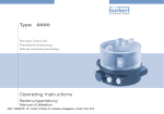
Type 7616
Micro dosing unit
Micro-Dosiereinheit
Unité de micro-dosage
Operating Instructions
Bedienungsanleitung
Manuel d‘utilisation
We reserve the right to make technical changes without notice.
Technische Änderungen vorbehalten.
Sous resérve de modification techniques.
© 2004 - 2009 Bürkert Werke GmbH & Co. KG
Operating Instructions 0906/06_EU-ML_00804671
Type 7616

Micro dosing unit Type 7616
Contents:
1. Operating Instructions....................................................................5
1.1.Symbols.......................................................................................................5
7. Installation................................................................................................ 10
7.1.Safety Instructions.............................................................................. 10
7.2.Preparatory work.................................................................................. 10
7.3.Fluid connections................................................................................. 11
2. Authorized Use..........................................................................................6
7.4.Installation............................................................................................... 11
2.1.Restrictions................................................................................................6
7.5.Electrical connection.......................................................................... 12
2.2.Predictable Misuse.................................................................................6
8. Start-Up.......................................................................................................... 12
3. Basic Safety Instructions..............................................................7
8.1.Safety Instructions.............................................................................. 12
4. General Information............................................................................8
8.2.Adjusting the stroke volume.......................................................... 12
4.1.Scope of Supply......................................................................................8
8.3.Functions.................................................................................................. 13
4.2.Warranty.......................................................................................................8
9. Dosing system (Optional)............................................................. 14
4.3.Licences.......................................................................................................8
9.1.Scope of Supply................................................................................... 14
4.4.Information on the Internet................................................................8
9.2.Connection.............................................................................................. 14
5. System Description................................................................................9
9.3.Software.................................................................................................... 15
6. Technical Specifications.................................................................9
9.4.Hardware.................................................................................................. 18
6.1.Operating Conditions............................................................................9
10. Malfunctions......................................................................................... 20
6.2.General Technical Data..................................................................... 10
11. Accessories............................................................................................ 21
english
3
Type 7616

12. Packaging and Transport......................................................... 21
13. Storage........................................................................................................ 22
14. Disposal...................................................................................................... 22
4
english
Type 7616
Operating Instructions
1.
Operating Instructions
The operating instructions describe the entire life cycle of the device.
Keep these instructions in a location which is easily accessible to
every user and make these instructions available to every new owner
of the device.
The operating instructions contain important safety information!
Failure to observe these instructions may result in hazardous
situations.
• The operating instructions must be read and understood.
1.1.
Symbols
Caution!
Warns of a possible danger!
• Failure to observe this warning may result in a medium or minor
injury.
Note!
Warns of damage to property!
• Failure to observe the warning may result in damage to the
device or the equipment.
indicates important additional information, tips and recommendations which are important for your safety and the
flawless functioning of the device.
Danger!
Warns of an immediate danger!
• Failure to observe the warning may result in a fatal or serious
injury.
Warning!
refers to information in these operating instructions or in
other documentation.
→→designates a procedure which you must carry out.
Warns of a potentially dangerous situation!
• Failure to observe the warning may result in serious injuries or
death.
english
5
Type 7616
Authorized Use
2.
Authorized Use
Non-authorized use of the dosing unit Type 7616 may be a
hazard to people, nearby equipment and the environment.
• The device is designed for the dosing of small fluid or gas
quantities. It may be used only for media listed in the chapter
"Technical specifications".
• Prior to the use of aggressive media, the resistance of the
media-wetted materials must be checked.
• Do not use the device outdoors without appropriate housing.
• Use according to the authorized data, operating conditions
and conditions of use specified in the contract documents
and operating instructions. These are described in the chapter
entitled "System description and Technical specifications".
• The device may be used only in conjunction with third-party
devices and components recommended and authorised by
Bürkert.
• Correct transportation, correct storage and installation and
careful use and maintenance are essential for reliable and
faultless operation.
• Use the device only as authorized.
6
english
2.1.
Restrictions
If exporting the System/Device, observe any existing restrictions.
2.2.
Predictable Misuse
• The micro dosing unit must not be used in potentially explosive
areas.
• Do not operate the device without suitable filtration of the input
medium.
• Do not put any loads on the housing (e.g. by placing objects on it
or standing on it).
• Do not make any external modifications to the device housings. Do
not paint the housing parts or screws.
Type 7616
Basic Safety Instructions
3.
Basic Safety Instructions
These safety instructions do not make allowance for any
• contingencies and events that may arise during the installation,
operation and maintenance of the devices.
• local safety regulations – the operator is responsible for observing
these regulations, also with reference to the installation personnel.
• After an interruption in the power supply or pneumatic supply,
ensure that the process is restarted in a defined or controlled
manner.
• The device may be operated only when in perfect condition and
in consideration of the operating instructions.
• The general rules of technology apply to application planning
and operation of the device.
Note!
Risk of burns/risk of fire if used continuously through hot
device surface!
• Keep the device away from highly flammable substances and
media and do not touch with bare hands.
General hazardous situations.
To prevent injury, ensure the following:
• Before loosening the lines and valves, turn off the pressure and
vent the lines.
• Before reaching into the device or the equipment, switch off the
power supply.
• Observe applicable accident prevention and safety regulations
for electrical equipment.
• That the system cannot be activated unintentionally.
• Installation and repair work may be carried out by authorised
technicians only and with the appropriate tools.
Electrostatic sensitive Components / Modules!
• The device contains electronic components which react sensitively
to electrostatic discharge (ESD). Contact with electrostatically
charged persons or objects is hazardous to these components.
In the worst case scenario, they will be destroyed immediately or
will fail after start-up.
• Observe the requirements in accordance with
DIN EN 61340-5-1 / 5-2 to minimise or avoid the possibility of
damage caused by sudden electrostatic discharge!
• Also ensure that you do not touch electronic components when
the power supply voltage is present!
Type 7616 was developed with due consideration given to
accepted safety rules and is state-of-the-art. Nevertheless,
dangerous situations may occur.
Failure to observe this operating manual and its operating
instructions as well as unauthorised tampering with the device
release us from any liability and also invalidte the warranty
covering the device and accessories!
english
7
Type 7616
General Information
4.
General Information
4.1.
Scope of Supply
Check immediately upon receipt of the delivery that the contents are
not damaged and that the type and scope agree with the delivery note
and packing list.
4.2.
Warranty
This document contains no promise or guarantee. Please refer to our
general terms of sales and delivery. The warranty is only valid if the
device is used as intended in accordance with the specified application
conditions.
The warranty extends only to defects in the Type 7616 and
its components.
If there are any discrepancies, please contact us immediately.
Germany
We accept no liability for any kind of collateral damage
which can occur due to failure or malfunction of the device.
Contact address:
Bürkert Fluid Control Systems
Sales Center
Chr.-Bürkert-Str. 13-17
D-74653 Ingelfingen
Tel.: +49 (0)7940 - 10 91 111
Fax: +49 (0)7940 - 10 91 448
E-mail: [email protected]
4.3.
Licences
The approval ratings on the Bürkert type plates concerns the Bürkert
products.
International
4.4.
Contact addresses can be found on the final pages of the printed
operating instructions.
The operating instructions and data sheets for Type 7616 can be found
on the Internet at:
And also on the internet at:
www.burkert.com
Type 7616
www.burkert.com
Bürkert
Company
Locations
Information on the Internet
Documentation
Manuals / Data sheets
The complete documentation is also available on CD which can be
ordered by quoting part no. 804625
8
english
Type 7616
System Description
5.
System Description
Due to the high reproducibility, the unit, which operates according to
the diaphragm pump principle, is especially suitable for the precise
dosing of very small fluid and gas quantities in the µl range.
The dosing unit can also be used for aggressive media because the
only media-wetted materials are PEEK and FFKM.
The symmetrical structure of the unit (2 x Type 6604, 1 x Type 6606,
PEEK connecting plate) allows bidirectional supply. The matching
electronic control system (RS232), including software, is available
as an option.
The supply rate of the dosing unit can be controlled via the mechanical
fine adjustment of the stroke and the frequency of the power supply
voltage. In addition to this, the supply rate depends on the viscosity of
the supplied medium as well as the flow resistances up and downstream
of the dosing unit (e.g. hose system)
6.
Technical Specifications
6.1.
Operating Conditions
Warning!
Burns, chemical burns through leaking medium.
• Prior to the use of aggressive media, the resistance of the
media-wetted parts must be checked.
You can find the chemical resistance chart for the materials on
Literature
Chemical
the internet under www.burkert.com
Resistance Chart.
If you are unsure, please contact your Bürkert Sales Centre.
Note!
Malfunction!
• Do not use Type 7616 outdoors without appropriate housing and
avoid heat sources that may cause the allowable temperature
range to be exceeded.
Allowable temperatures
Environmental temperature: 0 - +55 °C
Medium temperature:
+10 - +60 °C
Media: Aggressive, neutral gaseous and liquid media
and vapours. Check suitability according to the
chemical resistance chart.
Protection class: IP40
english
9
Type 7616
Installation
6.2.
General Technical Data
Observe the technical specifications as specified on the
type plate!
Max. delivery pressure:
2.5 bar
(overpressure towards the atmospheric
pressure)
Connections:
3 x rectangular connector
3 x stranded wire 200 mm
(other designs on request)
6.2.1. Type plate
Voltage / Type of current
Example:
Seal material
Made in Germany
Installation
7.1.
Safety Instructions
Caution!
Risk of injury from improper installation!
• Installation may be carried out by authorised technicians only
and with the appropriate tools!
• Before loosening the lines and valves, turn off the pressure and
vent the lines.
• Before reaching into the device or the equipment, switch off the
power supply and secure to prevent reactivation!
• Observe applicable accident prevention and safety regulations
for electrical equipment!
7.2.
Preparatory work
Housing material
→→Clean the connecting cables
7616 CC PK
24V DC 5W
DOSING UNIT
Output
Note!
Device designation
Malfunction due to unfiltered medium!
S/N 1050
Serial number
Crystallised medium or particles in the medium impair the
functionality of the device or result in the unit being destroyed.
Type
00202784
W16LP
Date of manufacture
(encoded)
Identification number of the
device
Fig. 1: Rating plate description
10
7.
english
→→Install upstream filter.
(Pore size 50 µm)
Type 7616
Installation
7.3.
→→Mount the hose connection as shown in the illustration.
Fluid connections
Warning!
Hose
Fitting
Burns, chemical burns through leaking medium.
• Prior to the use of aggressive media, the resistance of the
media-wetted parts must be checked. If you are unsure, please
contact your Bürkert Sales Centre.
→→Connect the fluid connections according to required
flow direction (see chart and diagram "Fluid connections").
Flow direction
Port 1
Port 2
Forward
Input
Output
Reverse
Output
Input
Ferrule
Fig. 3: Structure UNF ¼ – 28 for fluid connection
7.4.
Installation
Installation position: any position
→→Fasten the device.
Use the respective bores for M3 screws
(see figure "Installation").
Bore hole illustration:
M3
Rectangular connector
Valve 2
Port 1
Port 2
20.5
Bores forfastening
Valve 1
Valve 3
Fig. 2: Fluid connections
Fig. 4: Installation
english
11
Type 7616
Start-Up
Reversal of the flow direction
8.
Start-Up
To reverse the flow direction, exchange the control of valve 1 and
valve 3 (For valve configuration, see figure "Installation").
8.1.
Safety Instructions
7.5.
Warning!
Electrical connection
Connection type:Rectangular
connector stranded wire 200 mm
(Other designs on request).
Note the voltage as specified on the type plate!
→→Connect the device electrically.
The individual valves must be activated consecutively (refer
to the control diagram in chapter "Start-up / Functions").
Risk of injury from improper operation!
Improper operation may result in injuries as well as damage to the
device and the area around it.
• Before start-up, ensure that the operating personnel are familiar
with and completely understand the contents of the operating
instructions.
• Observe the safety instructions and intended use.
• Only adequately trained personnel may operate the equipment/
the device.
8.2.
Adjusting the stroke volume
Adjustment of the flow rate
Reduce flow rate
Increase flow rate
Turn clockwise
Turn anticlockwise
Fastening screw
Adjustment screw
Fig. 5: Adjustment stroke volume
12
english
Type 7616
Start-Up
Standard presetting: Times for maximum throughput:
Maximum stroke volume
→→Set the flow rate by turning the adjusting screw.
→→Fix the set flow rate with locking screw.
8.3.
While maintaining the times illustrated in the figure "Control
diagram" and an interval time of 0 ms, the maximum frequency
(15 Hz or 800 cycles/min) will be reached.
This corresponds to a throughput of approximately 4 ml/min with a
set maximum stroke volume.
Functions
8.3.1. Control diagram
Recommended times for maximum accuracy:
For dosing with the highest accuracy (Tolerance and reproducibility)
≤ ± 2%), the following times are recommended:
V1
ms
V2
30
0
T0
T1
50
T2
50
T3
50
T4
x
50
T5
T6
T1
This corresponds to a throughput of approximately 1.15 ml/min with
a set maximum stroke volume.
V3
10
0
ms
T0
T1
15
T2
15
T3
15
T4
0
5
T5
T6
T1
Fig. 6: Control diagram
Via the parameters (T0 – T6), the times for the valve control are set.
By changing the interval times (T6 – T1), the frequency can be
changed.
english
13
Type 7616
Dosing system (Optional)
9.
Dosing system (Optional)
9.1.
Scope of Supply
9.2.
Connection
→→Use the null modem cable to connect the dosing system (RS 232)
to the PC.
• Optional with 1 or 2 dosing unit(s) (24 V) in an aluminium housing
• 24 V power supply unit for the electrical power supply
• Null modem cable for the connection to PC (COM Port / RS 232)
• Control software
• Control electronics
→→Connect the power plug to the mains power supply.
→→Switch on the dosing system.
→→Start software ("pumpcontrol.exe").
→→Select COM Port (COM setup: Standard COM 1).
→→Begin the delivery process with "Start" of the respective dosing
unit (Pump 1 / Pump 2).
Medium connections
2 1
9.2.1. Measures in case of a malfunction
→→Check COM setup or select a different port.
→→Check the polarity of the power supply adaptor.
→→Connect the mains power cable to the dosing unit.
→→Switch on the dosing system.
→→Only start the software after the dosing system is connected
properly and turned ON.
→→Check the flow direction.
→→Check whether a null modem cable is being used.
RS 232
Power supply
Power switch
Fig. 7: Dosing system, dimensions in mm
14
english
Type 7616
Dosing system (Optional)
9.3.
Software
9.3.1. Main window
Menu description
Pump 1/2
Start
Starts the dosing unit 1 / 2
Stop
Stops the dosing unit 1 / 2
(closes all valves)
Flush
Flushing of the dosing unit 1 / 2
(opens all valves)
Both
During "Both", a synchronised control will take
place
Stop all
All dosing units will be de-energised (initial state)
Config
Definition of hardware, configuration and
parameters
COM setup
Selection of the serial connection
Reset
Settings will be reset
Exit
Quitting the programme
english
15
Type 7616
Dosing system (Optional)
9.3.2. Window "Hardware configuration"
The dosing system can be operated with or without PC.
If operation is without a PC, the control frequencies set in this
window (in fields 1-3) are used.
For this mode, additional configuration of the hardware is required.
Menu description
Panel "Pumps"
Number
Speed
[cycles/
min]
1)
2)
Selection of the dosing unit 1 / 2
1
Control frequency of pump 1 in mode A1)
1. Control frequency in mode B 2)
2
2. Control frequency in mode B 2)
3
3. Control frequency in mode B 2)
Mode A
Device is connected with PC; the control is
performed via the software.
Mode B
Device is in standalone mode.
The control takes place via the configurations that
were stored in the hardware.
The change-over of the hardware takes place via
jumpers.
Additional information on the change-over of the
hardware can be found in the following chapter
"Hardware".
Default
direction
Setting of the flow direction for dosing unit 1 / 2
(direct / reverse – forward / reverse)
Stop after xx
The respective dosing unit stops after xx cycles
cycles
Tuning
16
english
Configuration of the control diagram
Type 7616
Dosing system (Optional)
Panel "Bistable valves" / "Monostable valves"
9.3.3. Window "Pump tuning"
The settings refer to optional hardware features. Further
information on request.
OK
Save settings and close window
Cancel
Leaving window without changes
Load
Loads the device configuration from the
configuration file
Save
Saves the device configuration (including the tuning
parameters) in the configuration file.
Seven time parameters are entered here T0...T6 [ms] for the control
of the dosing units; the frequency is determined by the pause.
Pump tuning
OK
Save settings and close window
Cancel
Leaving window without changes
Defaults
Sets the time parameters back to the default
settings
See also the control diagram in chapter „Start-up /
Functions“
english
17
Type 7616
Dosing system (Optional)
9.4.
Hardware
Hardware allocation of the valve outputs (2) to the dosing units.
Dosing
unit
V0- / V0+
V1- / V1+
V2- / V2+
V3- / V3+
P11
P12
P13
-
P21
P22
P23
-
Valves (2)
1
2
Valve outputs
Pump valve
Outlet valve
Inlet valve
GND
+12 – +24 V DC
(according to the
nominal voltage of the valves)
Fig. 8: Overview, hardware allocation
18
english
Pump valve
Outlet valve
Dosing
unit 1
Dosing
unit 2
Fig. 9: Hardware allocation: Valves / Dosing unit
Valves (2)
Control (1)
Inlet valve
Type 7616
Dosing system (Optional)
Control (1) of the dosing unit based on the pre-configured
control frequencies
Control (1)
PIN
Fig. 10: Hardware allocation: Control / Dosing unit
Type
Status
Description
Error_OUT Output
high
Hardware error, stop in case of
overtemperature
Dln_0
Input
open
Dln_1
Input
open
Dln_0
Input
Ground
Dln_1
Input
open
Dln_0
Input
open
Dln_1
Input
Ground
Dln_0
Input
Ground
Dln_1
Input
Ground
Dln_2
Input
open
Dln_3
Input
open
Don_2
Input
Ground
Dln_3
Input
open
Dln_2
Input
open
Dln_3
Input
Ground
Dln_2
Input
Ground
Dln_3
Input
Ground
Z0: Operation via serial interface; both
dosing units are in standby after start-up
Z1: Operation via serial interface; both
dosing units start with default parameters
(if configured) after start-up
Z2: Operation via PIN Dln_2 ... Dln_7
(Digital inputs)
Z3: Operation via PIN Pot_0 and Pot_1
(Analogue inputs)
If Z2: Dosing unit 1 off
If Z2: Dosing unit 1 operates at its preconfigured frequency 1
(if configured)
If Z2: Dosing unit 1 operates at its preconfigured frequency 2
(if configured)
If Z2: Dosing unit 1 operates at its preconfigured frequency 3
(if configured)
english
19
Type 7616
Malfunctions
PIN
Type
Status
Dln_4
Input
open
Dln_5
Input
open
Dln_4
Input
Ground
Dln_5
Input
open
Dln_4
Input
open
Dln_5
Input
Ground
Dln_4
Input
Ground
Dln_5
Input
Ground
Description
10.
If Z2: Dosing unit 2 off
In case of malfunctions of the device
If Z2: Dosing unit 2 operates at its preconfigured frequency 1
(if configured)
If Z2: Dosing unit 2 operates at its preconfigured frequency 2
(if configured)
If Z2: Dosing unit 2 operates at its preconfigured frequency 3
(if configured)
Optional: Manually adjustable flow frequency for dosing unit 1
or 2 (22 kΩ-potentiometer)
PIN
Type
Status
Description
Pot_0
Input
22 kΩpotentiometer
ag. ground
If Z3: Analogue adjustable frequency
for dosing unit 1 via the potentiometer
Pot_1
Input
22 kΩpotentiometer
ag. ground
If Z3: Analogue adjustable frequency
for dosing unit 2 via the potentiometer
20
english
Malfunctions
→→Check the power supply.
→→Check the frequency.
→→Check the flow of the connection cables.
Type 7616
Accessories
11.
Accessories
12.
Caution!
Packaging and Transport
Note!
Risk of injury and/or damage by the use of incorrect parts!
Transport damages!
Incorrect accessories and unsuitable spare parts may cause
injuries and damage the device and the surrounding area.
• Use only original accessories and original spare parts from
Bürkert.
• During transportation protect the device against wet and dirt in
shock-resistant packaging.
Inadequately protected equipment may be damaged during
transport.
• Avoid exceeding or dropping below the allowable storage
temperature.
Auxiliary parts for micro dosing unit Type 7616
Part
Designation
Order no.
Rectangular connector
with 3 m cable
(grid 5.08 mm)
133 486
Rectangular connector
with 300 mm stranded wires 644 068
(grid 5.08 mm)
Rectangular connector
644 067
with 2 individual contacts
Fittings and hoses
see data sheet
Type 1013
english
21
Type 7616
Storage
13.
Storage
14. Disposal
→→Dispose of the device and packaging in an environmentally friendly
Note!
Incorrect storage may damage the device.
• Store the device in a dry and dust-free location!
• Storage temperature. 0 – 55 °C.
manner.
Note!
Damage to the environment caused by device components
contaminated with media.
• Observe applicable regulations on disposal and the environment.
Note:
Observe national waste disposal regulations.
22
english
Typ 7616

Micro-Dosiereinheit Typ 7616
Inhalt:
1. Die Bedienungsanleitung............................................................. 25
1.1.Darstellungsmittel............................................................................... 25
7. Installation................................................................................................ 30
7.1.Sicherheitshinweise........................................................................... 30
7.2.Vorbereitende Arbeiten..................................................................... 30
7.3.Fluidische Anschlüsse...................................................................... 31
2. Bestimmungsgemässe Verwendung.................................... 26
7.4.Einbau........................................................................................................ 31
2.1.Beschränkungen.................................................................................. 26
7.5.Elektrischer Anschluss..................................................................... 32
2.2.Vorhersehbarer Fehlgebrauch...................................................... 26
8. Inbetriebnahme....................................................................................... 32
3. Grundlegende Sicherheitshinweise.................................. 27
8.1.Sicherheitshinweise........................................................................... 32
4. Allgemeine Hinweise........................................................................... 28
8.2.Einstellung des Hubvolumens...................................................... 32
4.1.Lieferumfang.......................................................................................... 28
8.3.Funktionen............................................................................................... 33
4.2.Gewährleistung..................................................................................... 28
9. Dosiersystem (Optional)................................................................ 34
4.3.Zulassungen........................................................................................... 28
9.1.Lieferumfang.......................................................................................... 34
4.4.Informationen im Internet................................................................ 28
9.2.Anschluss................................................................................................. 34
5. Systembeschreibung........................................................................ 29
9.3.Software.................................................................................................... 35
6. Technische Daten................................................................................. 29
9.4.Hardware.................................................................................................. 38
6.1.Betriebsbedingungen........................................................................ 29
10. Störungen................................................................................................. 40
6.2.Allgemeine Technische Daten...................................................... 30
11. Zubehör....................................................................................................... 41
deutsch
23
Typ 7616

12. Verpackung, Transport............................................................... 41
13. Lagerung.................................................................................................... 42
14. Entsorgung............................................................................................. 42
24
deutsch
Typ 7616
Die Bedienungsanleitung
1.
Die Bedienungsanleitung
Die Bedienungsanleitung beschreibt den gesamten Lebenszyklus
des Gerätes. Bewahren Sie diese Anleitung so auf, dass sie für jeden
Benutzer gut zugänglich ist und jedem neuen Eigentümer des Gerätes
wieder zur Verfügung steht.
Die Bedienungsanleitung enthält wichtige Informationen zur
Sicherheit!
Das Nichtbeachten dieser Hinweise kann zu gefährlichen Situationen führen.
• Die Bedienungsanleitung muss gelesen und verstanden werden.
1.1.
Darstellungsmittel
Gefahr!
Warnt vor einer unmittelbaren Gefahr!
• Bei Nichtbeachtung sind Tod oder schwere Verletzungen die
Folge.
Vorsicht!
Warnt vor einer möglichen Gefährdung!
• Nichtbeachtung kann mittelschwere oder leichte Verletzungen
zur Folge haben.
Hinweis!
Warnt vor Sachschäden!
• Bei Nichtbeachtung kann das Gerät oder die Anlage beschädigt
werden.
bezeichnet wichtige Zusatzinformationen, Tipps und Empfehlungen, die für Ihre Sicherheit und die einwandfreie
Funktion des Gerätes wichtig sind.
verweist auf Informationen in dieser Bedienungsanleitung
oder in anderen Dokumentationen.
→→markiert einen Arbeitsschritt, den sie ausführen müssen.
Warnung!
Warnt vor einer möglicherweise gefährlichen Situation!
• Bei Nichtbeachtung drohen schwere Verletzungen oder Tod.
deutsch
25
Typ 7616
Bestimmungsgemässe Verwendung
2.
Bestimmungsgemässe
Verwendung
Bei nicht bestimmungsgemäßem Einsatz der Micro-Dosiereinheit Typ 7616 können Gefahren für Personen, Anlagen
in der Umgebung und die Umwelt entstehehen.
• Das Gerät ist für die Dosierung kleiner Flüssigkeits- und Gasmengen konzipiert. Es darf nur für die im Kapitel „Technische
Daten“ aufgeführten Medien eingesetzt werden.
• Vor Einsatz aggressiver Medien muss die Beständigkeit der
mediumsberührten Materialien geprüft werden.
• Das Gerät nicht ohne entsprechendes Gehäuse im Außenbereich einsetzen.
• Für den Einsatz die in den Vertragsdokumenten und der Bedienungsanleitung spezifizierten zulässigen Daten, Betriebs- und
Einsatzbedingungen beachten. Diese sind im Kapitel „Systembeschreibung und Technische Daten“ beschrieben sind.
• Das Gerät nur in Verbindung mit von Bürkert empfohlenen bzw.
zugelassenen Fremdgeräten und -komponenten einsetzen.
• Voraussetzungen für den sicheren und einwandfreien Betrieb
sind sachgemäßer Transport, sachgemäße Lagerung und Installation sowie sorgfältige Bedienung und Instandhaltung.
• Setzen Sie das Gerät nur bestimmungsgemäß ein.
26
deutsch
2.1.
Beschränkungen
Beachten Sie bei der Ausfuhr des Systems/Gerätes gegebenenfalls
bestehende Beschränkungen.
2.2.
Vorhersehbarer Fehlgebrauch
• Die Micro-Dosiereinheit darf nicht in explosionsgefährdeten
Bereichen eingesetzt werden.
• Betreiben Sie das Gerät nicht ohne eine geeignete Filterung des
Eingangsmediums.
• Belasten Sie das Gehäuse nicht mechanisch (z. B. durch Ablage
von Gegenständen oder als Trittstufe).
• Nehmen Sie keine äußerlichen Veränderungen an den Gerätegehäusen vor. Gehäuseteile und Schrauben nicht lackieren.
Typ 7616
Grundlegende Sicherheitshinweise
3.
Grundlegende
Sicherheitshinweise
Diese Sicherheitshinweise berücksichtigen keine
• Zufälligkeiten und Ereignisse, die bei Montage, Betrieb und Wartung
der Geräte auftreten können.
• ortsbezogenen Sicherheitsbestimmungen, für deren Einhaltung, auch
in Bezug auf das Montagepersonal, der Betreiber verantwortlich
ist.
Verbrennungsgefahr/Brandgefahr bei Dauerbetrieb durch
heiße Geräteberfläche!
• Das Gerät von leicht brennbaren Stoffen und Medien fernhalten
und nicht mit bloßen Händen berühren.
Allgemeine Gefahrensituationen.
Zum Schutz vor Verletzungen beachten:
• Vor dem Lösen von Leitungen und Ventilen den Druck abschalten und Leitungen entlüften.
• Vor Eingriffen in das Gerät oder die Anlage, Spannung
abschalten.
• Die geltenden Unfallverhütungs- und Sicherheitsbestimmungen
für elektrische Geräte beachten.
• Dass die Anlage nicht unbeabsichtigt betätigt werden kann.
• Installations- und Instandhaltungsarbeiten dürfen nur von autorisiertem Fachpersonal mit geeignetem Werkzeug ausgeführt
werden.
• Nach einer Unterbrechung der elektrischen oder pneumatischen
Versorgung ist ein definierter oder kontrollierter Wiederanlauf
des Prozesses zu gewährleisten.
• Das Gerät darf nur in einwandfreiem Zustand und unter Beachtung der Bedienungsanleitung betrieben werden.
• Für die Einsatzplanung und den Betrieb des Gerätes müssen
die allgemeinen Regeln der Technik eingehalten werden.
Hinweis!
Elektrostatisch gefährdete Bauelemente / Baugruppen!
• Das Gerät enthält elektronische Bauelemente, die gegen elektrostatische Entladung (ESD) empfindlich reagieren. Berührung
mit elektrostatisch aufgeladenen Personen oder Gegenständen
gefährdet diese Bauelemente. Im schlimmsten Fall werden sie
sofort zerstört oder fallen nach der Inbetriebnahme aus.
• Beachten Sie die Anforderungen nach DIN EN 61340-5-1 / 5-2,
um die Möglichkeit eines Schadens durch schlagartige elektrostatische Entladung zu minimieren bzw. zu vermeiden!
• Achten Sie ebenso darauf, dass Sie elektronische Bauelemente
nicht bei anliegender Versorgungsspannung berühren!
Der Typ 7616 wurde unter Einbeziehung der anerkannten
sicherheitstechnischen Regeln entwickelt und entspricht dem
Stand der Technik. Trotzdem können Gefahren entstehen.
Bei Nichtbeachtung dieser Bedinungsanleitung und ihrer
Hinweise sowie bei unzulässigen Eingriffen in das Gerät
entfällt jegliche Haftung unsererseits, ebenso erlischt die
Gewährleistung auf Geräte und Zubehörteile!
deutsch
27
Typ 7616
Allgemeine Hinweise
4.
Allgemeine Hinweise
4.1.
Lieferumfang
Überzeugen Sie sich unmittelbar nach Erhalt der Sendung, dass der
Inhalt nicht beschädigt ist und in Art und Umfang mit dem Lieferschein
bzw. der Packliste übereinstimmt.
4.2.
Diese Druckschrift enthält keine Garantiezusagen. Wir verweisen hierzu
auf unsere allgemeinen Verkaufs- und Lieferbedingungen. Voraussetzung für die Gewährleistung ist der bestimmungsgemäße Gebrauch
des Gerätes unter Beachtung der spezifizierten Einsatzbedingungen.
Die Gewährleistung erstreckt sich nur auf die Fehlerfreiheit
des Typs 7616 und seiner Bauteile.
Bei Unstimmigkeiten wenden Sie sich bitte umgehend an uns.
Für Folgeschäden jeglicher Art, die durch Ausfall oder Fehlfunktion des Gerätes entstehen könnten, wird keine Haftung
übernommen.
Deutschland
Kontaktadresse:
Bürkert Fluid Control Systems
Sales Center
Chr.-Bürkert-Str. 13-17
D-74653 Ingelfingen
Tel. : +49 (0) 7940 - 10 91 111
Fax: +49 (0) 7940 - 10 91 448
E-mail: [email protected]
4.3.
4.4.
Die Kontaktadressen finden Sie auf den letzten Seiten der
gedruckten Bedienungsanleitung.
Außerdem im Internet unter:
28
Bürkert
Company
Zulassungen
Die auf den Bürkert Typschildern aufgebrachte Zulassungskennzeichnung bezieht sich auf die Bürkert Produkte.
International
www.burkert.com
Gewährleistung
Locations
deutsch
Informationen im Internet
Bedienungsanleitungen und Datenblätter zum Typ 7616 finden Sie
im Internet unter:
Technische Daten
www.buerkert.de
blätter
Typ 7616
Betriebsanleitung / Daten-
Desweiteren steht eine komplette Dokumentation auf CD bereit, die
unter der Identnummer 804625 bestellt werden kann.
Typ 7616
Systembeschreibung
5.
Systembeschreibung
Die nach dem Membranpumpenprinzip arbeitende Einheit eignet sich
durch die hohe Reproduzierbarkeit besonders für die präzise Dosierung
kleinster Flüssigkeits- und Gasmengen im µl-Bereich.
Da die einzigen medienberührten Materialien PEEK und FFKM
sind, kann die Dosiereinheit auch für aggressive Medien eingesetzt
werden.
Der symmetrische Aufbau der Einheit (2 x Typ 6604, 1 x Typ 6606,
PEEK-Anschlussplatte) erlaubt eine bidirektionale Förderung. Die
passende Ansteuerungselektronik (RS232) inklusive Software ist
optional erhältlich.
Die Förderrate der Dosiereinheit ist beeinflussbar durch die mechanische Feineinstellung des Hubs und die Frequenz der Versorgungsspannung. Darüber hinaus ist die Förderrate abhängig von der Viskosität
des geförderten Mediums sowie den Strömungswiderständen vor und
nach der Dosiereinheit (z.B. Verschlauchung)
6.
Technische Daten
6.1.
Betriebsbedingungen
Warnung!
Verbrennung, Verätzung durch austretendes Medium.
• Vor Einsatz aggressiver Medien muss die Beständigkeit der
mediumsberührten Teile geprüft werden.
Die Bürkert-Beständigkeitstabelle der Werkstoffe finden
Dokumentation
Sie im Internet unter www.buerkert.de
Beständigkeitstabelle.
Kataloge & Broschüren
Wenden Sie sich bei Unklarheiten an Ihre BürkertVertriebsniederlassung.
Hinweis!
Funktionsausfall!
• Typ 7616 nicht ohne entsprechendes Gehäuse im Außenbereich einsetzen und Wärmequellen, die zur Überschreitung des
zulässigen Temperaturbereichs führen können, vermeiden.
Zulässigen Temperaturen
Umgebungstemperatur:
Mediumstemperatur:
0 ... +55 °C
+10 ... +60 °C
Medien: Aggressive, neutrale gasförmige und flüssige Medien
und Dämpfe. Eignung laut Beständigkeitstabelle
überprüfen.
Schutzart: IP40
deutsch
29
Typ 7616
Installation
6.2.
Allgemeine Technische Daten
Die Technischen Daten laut Typschild beachten!
7.
Installation
7.1.
Sicherheitshinweise
Vorsicht!
Max. Förderdruck:
2,5 bar
(Überdruck zum Atmosphärendruck)
3 x Recheckstecker
Anschlüsse:
3 x Litze 200 mm (andere
Ausführungen auf Anfrage
6.2.1. Typschild
Spannung / Stromart
Beispiel:
7.2.
Dichtwerkstoff
Made in Germany
Typ
7616 CC PK
24V DC 5W
DOSING UNIT
S/N 1050
00202784
W16LP
Vorbereitende Arbeiten
Gehäusewerkstoff
→→Anschlussleitungen reinigen
Leistung
Hinweis!
Gerätebezeichnung
Seriennummer
Herstellerdatum
(verschlüsselt)
Identnummer des Gerätes
Bild 1: Typschildbeschreibung
30
Verletzungsgefahr bei unsachgemäßer Installation!
• Die Montage darf nur autorisiertes Fachpersonal mit geeignetem Werkzeug durchführen!
• Vor dem Lösen von Leitungen und Ventilen den Druck abschalten und Leitungen entlüften.
• Vor Eingriffen in das Gerät oder die Anlage, Spannung abschalten und vor Wiedereinschalten sichern!
• Die geltenden Unfallverhütungs- und Sicherheitsbestimmungen
für elektrische Geräte beachten!
deutsch
Funktionsausfall durch ungefiltertes Medium!
Durch auskristallisiertes Medium oder Partikel im Medium wird das
Gerät in seiner Funktion beeinträchtigt oder fällt ganz aus.
→→Vorgelagerten Filter einbauen.
(Porengröße 50 µm)
Typ 7616
Installation
7.3.
→→Schlauchanschluss wie im Bild dargestellt montieren.
Fluidische Anschlüsse
Warnung!
Schlauch
Fitting
Verbrennung, Verätzung durch austretendes Medium.
• Vor Einsatz aggressiver Medien muss die Beständigkeit der
mediumsberührten Teile geprüft werden. Wenden Sie sich bei
Unklarheiten an Ihre Bürkert-Vertriebsniederlassung.
→→Fluidische Anschlüsse entsprechend der gewünschten
Förderrichtung anschließen (siehe Tabelle und Bild „Fluidische
Anschlüsse“).
Förderrichtung
Port 1
Port 2
vorwärts
Eingang
Ausgang
rückwärts
Ausgang
Eingang
Ferrule
Bild 3: Aufbau UNF ¼ - 28 für fluidischen Anschluss
7.4.
Einbau
Einbaulage: beliebig
→→Gerät festschrauben.
Die dafür vorgesehenen Bohrungen für Schrauben M3 benutzen
(siehe Bild „Einbau“).
Rechteckstecker
Port 1
Port 2
Bohrbild:
M3
Ventil 2
20,5
Ventil 1
Bohrungen zur
Befestigung
Ventil 3
Bild 2: Fluidische Anschlüsse
Bild 4: Einbau
deutsch
31
Typ 7616
Inbetriebnahme
Umkehren der Förderrichtung
8.
Inbetriebnahme
Zum Umkehren der Förderrichtung die Ansteuerung von Ventil 1 und
Ventil 3 tauschen (Ventilanordnung siehe Bild „Einbau“).
8.1.
Sicherheitshinweise
7.5.
Warnung!
Elektrischer Anschluss
Anschlussart:Rechteckstecker
Litze 200 mm (Andere Ausführungen auf
Anfrage).
Spannung laut Typschild beachten!
→→Gerät elektrisch anschließen.
Die einzelnen Ventile sind sequenziell anzusteuern (siehe
Steuerschema in Kapitel “Inbetriebnahme / Funktionen“).
Verletzungsgefahr bei unsachgemäßem Betrieb!
Nicht sachgemäßer Betrieb kann zu Verletzungen, sowie Schäden
am Gerät und seiner Umgebung führen.
• Vor der Inbetriebnahme muss gewährleistet sein, dass der Inhalt
der Bedienungsanleitung dem Bedienungspersonal bekannt ist
und vollständig verstanden wurde.
• Die Sicherheitshinweise und die Bestimmungsgemäße Verwendung müssen beachtet werden.
• Nur ausreichend geschultes Personal darf die Anlage/das Gerät
in Betrieb nehmen.
8.2.
Einstellung des Hubvolumens
Justierung der Durchflussmenge
Durchflussmenge
verringern
Durchflussmenge
vergrößern
Drehen im
Uhrzeigersinn
Drehen gegen den
Uhrzeigersinn
Feststellschraube
Justierschraube
Bild 5: Einstellung Hubvolumen
32
deutsch
Typ 7616
Inbetriebnahme
Standard-Voreinstellung: Maximales Hubvolumen
→→Durchflussmenge durch Drehen der Justierschraube einstellen.
→→Eingestellte Durchflussmenge mit Feststellschraube arretieren.
8.3.
Funktionen
Zeiten für maximalen Durchsatz:
Bei Beibehaltung der im Bild „Steuerschema“ dargestellen Zeiten
und einer Pausenzeit von 0 ms wird die maximale Frequenz (15 Hz
bzw. 800 Zyklen/min) erreicht.
Dies entspricht einem Durchsatz von ca. 4 ml/min bei max. eingestelltem Hubvolumen.
8.3.1. Steuerschema
Empfohlene Zeiten für höchste Präzision:
Für eine Dosierung mit höchster Präzision (Abweichung und Reproduzierbarkeit) ≤ ± 2%) werden folgende Zeiten empfohlen:
V1
ms
V2
30
0
T0
T1
50
T2
50
T3
50
T4
x
50
T5
T6
T1
Dies entspricht einem Durchsatz von ca. 1,15 ml/min bei max. eingestelltem Hubvolumen.
V3
ms
10
0
T0
T1
15
T2
15
T3
15
T4
0
5
T5
T6
T1
Bild 6: Steuerschema
Über die Parameter (T0 ... T6) werden die Zeiten für die Steuerung
der Ventile eingestellt.
Durch Verändern der Pausenzeit (T6 - T1) kann die Frequenz verändert werden.
deutsch
33
Typ 7616
Dosiersystem (Optional)
9.
Dosiersystem (Optional)
9.1.
Lieferumfang
9.2.
Anschluss
→→Dosiersystem (RS 232) mit dem Null-Modemkabel an den PC
anschließen.
• Wahlweise mit 1 oder 2 Dosiereinheit/en (24 V) in einem
Aluminium-Gehäuse
• 24 V Netzteil zur Spannungsversorgung
• Null-Modemkabel zum Anschluss am PC (COM-Port / RS 232)
• Ansteuersoftware
• Ansteuerelektronik
→→Zur Spannungsversorgung den Netzstecker einstecken.
→→Dosiersystem anschalten.
→→Software starten („pumpcontrol.exe“).
→→COM-Port wählen (COM-Setup: Standard COM 1).
→→Fördervorgang starten mit „Start“ der jeweiligen Dosiereinheit
(Pump 1 / Pump 2).
Mediumsanschlüsse
2 1
9.2.1. Maßnahmen bei Fehlfunktion
→→COM-Setup überprüfen, bzw. anderen Port wählen.
→→Polarität des Netzadapters prüfen.
→→Netzkabel am Dosiersystem anschließen.
→→Dosiersystem einschalten.
→→Die Software erst starten, wenn das Dosiersystem korrekt angeschlossen bzw. eingeschaltet ist.
→→Förderrichtung prüfen.
→→Überprüfen ob ein Nullmodemkabel verwendet wird.
RS 232
Spannungsversorgung
Netzschalter
Bild 7: Dosiersystem, Abmessungen in mm
34
deutsch
Typ 7616
Dosiersystem (Optional)
9.3.
Software
9.3.1. Hauptfenster
Menübeschreibung
Pump 1/2
Start
Startet die Dosiereinheit 1 /2
Stop
Stoppt die Dosiereinheit 1 / 2
(schließt alle Ventile)
Flush
Spülen der Dosiereinheit 1 / 2
(öffnet alle Ventile)
Both
Bei Both erfolgt eine synchrone Ansteuerung
Stop all
Schaltet alle Dosiereinheiten in den stromlosen
Zustand (Ausgangszustand)
Config
Definition von Hardware, Konfiguration und
Parametern
COM-Setup
Auswahl des seriellen Anschlusses
Reset
Zurücksetzen der Einstellungen
Exit
Verlassen des Programms
deutsch
35
Typ 7616
Dosiersystem (Optional)
9.3.2. Fenster „Hardwarekonfiguration“
Das Dosiersystem kann mit und ohne PC betrieben werden.
Bei Betrieb ohne PC werden die in diesem Fenster (in den Feldern
1-3) eingestellten Ansteuerfrequenzen verwendet.
Für diesen Modus ist eine zusätzliche Konfiguration der Hardware
erforderlich.
Menübeschreibung
Panel „Pumps“
Number
Speed
[cycles/
min]
1)
2)
Auswahl der Dosiereinheit 1 / 2
1
Ansteuerfrequenz der Pumpe 1 im Modus A1)
1. Ansteuerfrequenz im Modus B 2)
2
2. Ansteuerfrequenz im Modus B 2)
3
3. Ansteuerfrequenz im Modus B 2)
Modus A
Gerät ist mit PC verbunden, die Ansteuerung
erfolgt über die Software
Modus B
Gerät ist im Stand-Alone-Betrieb.
Die Ansteuerung erfolgt über die in der Hardware
hinterlegten Konfigurationen.
Die Umstellung der Hardware erfolgt über Jumper.
Nähere Informationen zur Hardwareumstellung im
nachfolgenden Abschnitt „Hardware“.
Default
Direction
Einstellung der Förderrichtung für Dosiereinheit 1 /
2 (direct / reverse – vorwärts / rückwärts)
Stop after xx Die entspechende Dosiereinheit stoppt nach xx
Zyklen
cycles
Tuning
36
deutsch
Konfiguration des Ansteuerschemas
Typ 7616
Dosiersystem (Optional)
Panel „Bistable Valves“ / „Monostable Valves“
9.3.3. Fenster „Pump-Tuning“
Die Einstellungen beziehen sich auf optionale Hardware-Features.
Nähere Informationen auf Anfrage.
OK
Einstellungen speichern und Fenster schließen
Cancel
Load
Fenster ohne Änderungen verlassen
Save
Lädt Gerätekonfiguration aus Konfigurationsdatei
Speichert Gerätekonfiguration (einschließlich der
Tuningparameter) in Konfigurationsdatei.
Hier erfolgt die Eingabe von sieben Zeitparametern T0...T6 [ms] zur
Steuerung der Dosiereinheiten; die Frequenz wird bestimmt durch
die Pause.
Pump Tuning
OK
Einstellungen speichern und Fenster schließen
Cancel
Fenster ohne Änderungen verlassen
Defaults
Setzt die Zeitparameter auf die Standardeinstellungen zurück
Siehe auch Steuerschema in Kapitel “Inbetriebnahme /
Funktionen“.
deutsch
37
Typ 7616
Dosiersystem (Optional)
Hardware
Hardwarezuordnung der Ventilausgänge (2) zu den
Dosiereinheiten
Steuerung (1)
Ventile (2)
Dosiereinheit
1
2
Ventilausgänge
V0- / V0+
V1- / V1+
V2- / V2+
V3- / V3+
P11
P12
P13
-
P21
P22
P23
-
Eingangsventil
Pumpventil
Ausgangsventil
Eingangsventil
Pumpventil
Ausgangsventil
GND
+12 ... +24 V DC
(entsprechend der
Nennspannung der Ventile)
Dosiereinheit 2
Bild 9: Hardwarezuordnung: Ventile / Dosiereinheit
Bild 8: Übersicht, Hardwarezuordnung
38
Dosiereinheit 1
deutsch
Ventile (2)
9.4.
Typ 7616
Dosiersystem (Optional)
Steuerung (1) der Dosiereinheit anhand der vorkonfigurierten
Ansteuerfrequenzen
Steuerung (1)
PIN
Bild 10:Hardwarezuordnung: Steuerung / Dosiereinheit
Typ
Zustand Bedeutung
Error_OUT Ausgang high
Hardwarefehler, Halt bei Übertemperatur
Dln_0
Eingang
open
Dln_1
Eingang
open
Z0: Bedienung über serielle Schnittstelle, beide Dosiereinheiten nach Einschalten im Standby
Dln_0
Eingang
Ground
Dln_1
Eingang
open
Dln_0
Eingang
open
Dln_1
Eingang
Ground
Dln_0
Eingang
Ground
Dln_1
Eingang
Ground
Dln_2
Eingang
open
Dln_3
Eingang
open
Don_2
Eingang
Ground
Dln_3
Eingang
open
Dln_2
Eingang
open
Dln_3
Eingang
Ground
Dln_2
Eingang
Ground
Dln_3
Eingang
Ground
deutsch
Z1: Bedienung über serielle Schnittstelle, beide Dosiereinheiten starten
nach Einschalten mit Default_Parametern (falls konfiguriert)
Z2: Bedienung über PIN Dln_2 ... Dln_7
(Digitaleingänge)
Z3: Bedienung über PIN Pot_0 und
Pot_1 (Analogeingänge)
Falls Z2: Dosiereinheit 1 aus
Falls Z2: Dosiereinheit 1 läuft mit ihrer
vorkonfigurierten Frequenz1
(falls konfiguriert)
Falls Z2: Dosiereinheit 1 läuft mit ihrer
vorkonfigurierten Frequenz 2
(falls konfiguriert)
Falls Z2: Dosiereinheit 1 läuft mit ihrer
vorkonfigurierten Frequenz 3
(falls konfiguriert)
39
Typ 7616
Störungen
PIN
Typ
Zustand Bedeutung
Dln_4
Eingang
open
Dln_5
Eingang
open
Dln_4
Eingang
Ground
Dln_5
Eingang
open
Dln_4
Eingang
open
Dln_5
Eingang
Ground
Dln_4
Eingang
Ground
Dln_5
Eingang
Ground
10.
Falls Z2: Dosiereinheit 2 aus
Falls Z2: Dosiereinheit 2 läuft mit ihrer
vorkonfigurierten Frequenz1
(falls konfiguriert)
Falls Z2: Dosiereinheit 2 läuft mit ihrer
vorkonfigurierten Frequenz 2
(falls konfiguriert)
Falls Z2: Dosiereinheit 2 läuft mit ihrer
vorkonfigurierten Frequenz 3
(falls konfiguriert)
Optional: Manuell einstellbare Förderfrequenz für Dosiereinheit
1 oder 2 (22 kΩ-Poti)
PIN
Typ
Zustand
Pot_0
Eingang
22kΩ-Poti g. Falls Z3: Über das Poti analog einGround
stellbare Frequenz für Dosiereinheit 1
Pot_1
Eingang
22kΩ-Poti g. Falls Z3: Über das Poti analog einGround
stellbare Frequenz für Dosiereinheit 2
40
Bedeutung
deutsch
Störungen
Bei Störungen des Gerätes
→→Spannung kontrollieren.
→→Frequenz überprüfen.
→→Durchfluss der Anschlussleitungen kontrollieren.
Typ 7616
Zubehör
11.
Zubehör
12.
Vorsicht!
Verpackung, Transport
Hinweis!
Verletzungsgefahr, Sachschäden durch falsche Teile!
Falsches Zubehör und ungeeignete Ersatzteile können Verletzungen und Schäden am Gerät und dessen Umgebung
verursachen
• Nur Originalzubehör sowie Originalersatzteile der Firma Bürkert
verwenden.
Transportschäden!
Unzureichend geschützte Geräte können durch den Transport
beschädigt werden.
• Gerät vor Nässe und Schmutz geschützt in einer stoßfesten
Verpackung transportieren.
• Eine Über- bzw. Unterschreitung der zulässigen Lagertemperatur vermeiden.
Zubehörteile für Micro-Dosiereinheit Typ 7616
Teil
Bezeichnung
Bestell-Nr.
Rechteckverbinder mit
3 m Kabel
(Raster 5,08 mm)
133 486
Rechteckverbinder mit
300 mm Litzen
(Raster 5,08 mm)
644 068
Rechteckverbinder mit
2 Einzelkontakten
644 067
Fittings und Schläuche
siehe Datenblatt Typ 1013
deutsch
41
Typ 7616
Lagerung
13.
Lagerung
14. Entsorgung
→→Entsorgen Sie das Gerät und die Verpackung umweltgerecht.
Hinweis!
Falsche Lagerung kann Schäden am Gerät verursachen.
• Gerät trocken und staubfrei lagern!
Hinweis!
Umweltschäden durch von Medien kontaminierte Geräteteile.
• Geltende Entsorgungsvorschriften und Umweltbestimmungen
einhalten.
• Lagertemperatur. 0 … 55 °C.
Hinweis:
Beachten Sie die nationalen Abfallbeseitigungsvorschriften.
42
deutsch
Type 7616

Unité de micro-dosage type 7616
7. Installation................................................................................................ 50
Sommaire:
1. Les instructions de service................................................................................45
1.1.Moyens de représentation.............................................................. 45
7.1.Consignes de sécurité...................................................................... 50
7.2.Travaux préparatoires........................................................................ 50
7.3.Raccords fluidiques............................................................................ 51
2. Utilisation conforme....................................................................... 46
7.4.Montage.................................................................................................... 51
2.1.Limitations............................................................................................... 46
7.5.Raccordement électrique................................................................ 52
2.2.Mauvaise utilisation prévisible...................................................... 46
8. Mise en service........................................................................................ 52
3. Consignes de sécurité fondamentales.......................... 47
8.1.Consignes de sécurité...................................................................... 52
4. Indications générales..................................................................... 48
8.2.Réglage du volume engendré....................................................... 52
4.1.Fourniture................................................................................................. 48
8.3.Fonctions.................................................................................................. 53
4.2.Garantie légale...................................................................................... 48
9. Système de dosage (En option)............................................... 54
4.3.Homologations...................................................................................... 48
9.1.Fourniture................................................................................................. 54
4.4.Informations sur Internet................................................................. 48
9.2.Raccordement........................................................................................ 54
5. Description du système................................................................. 49
9.3.Logiciel...................................................................................................... 55
6. Caractéristiques techniques................................................. 49
9.4.Matériel...................................................................................................... 58
6.1.Conditions d’exploitation................................................................. 49
10. Pannes........................................................................................................... 60
6.2.Caractéristiques techniques générales................................... 50
11. Accessoires............................................................................................ 61
français
43
Type 7616

12. Emballage, transport................................................................... 61
13. Stockage.................................................................................................... 62
14. Elimination................................................................................................ 62
44
français
Type 7616
Les instructions de service
1.
Les instructions de service
Les instructions de service décrivent le cycle de vie complet de l’appareil.
Conservez ces instructions de sorte qu’elles soient accessibles à tout
utilisateur et à disposition de tout nouveau propriétaire.
Les instructions de service contiennent des informations
importantes sur la sécurité !
Le non-respect de ces consignes peut entraîner des situations
dangereuses.
• Les instructions de service doivent être lues et comprises.
1.1.
Moyens de représentation
Attention !
Met en garde contre un risque possible !
• Le non-respect peut entraîner des blessures légères ou de
moyenne gravité.
Remarque !
Met en garde contre des dommages matériels !
• L’appareil ou l’installation peut être endommagé(e) en cas de
non-respect.
désigne des informations supplémentaires importantes, des
conseils et des recommandations d’importance pour votre
sécurité et le parfait fonctionnement de l’appareil.
Danger !
Met en garde contre un danger imminent !
• Le non-respect peut entraîner la mort ou de graves blessures.
renvoie à des informations dans ces instructions de service
ou dans d’autres documentations.
→→identifie une opération que vous devez effectuer.
Avertissement !
Met en garde contre une situation éventuellement dangereuse !
• Risque de blessures graves, voire la mort en cas de non-respect.
français
45
Type 7616
Utilisation conforme
2.
Utilisation conforme
L’utilisation non conforme de l’unité de micro-dosage type
7616 peut présenter des dangers pour les personnes, les
installations proches et l’environnement.
• L’appareil est conçu pour le dosage de petites quantités de
liquide et de gaz. Il ne doit être utilisé que pour les fluides repris
au chapitre « Caractéristiques techniques ».
• Avant utilisation de fluides agressifs, il convient de contrôler la
résistance des matériaux en contact avec le fluide.
• N’utilisez pas l’appareil à l’extérieur sans mesures de protection
adaptées.
• Lors de l’utilisation, il convient de respecter les données et
conditions d’utilisation et d’exploitation admissibles spécifiées
dans les instructions de service et dans les documents
contractuels. Celles-ci sont décrites au chapitre « Description
du système et caractéristiques techniques ».
• L’appareil peut être utilisé uniquement en association avec
les appareils et composants étrangers recommandés et
homologués par Bürkert.
• Les conditions pour l’utilisation sûre et parfaite sont un
transport, un stockage et une installation dans les règles ainsi
qu’une parfaite utilisation et maintenance.
• Veillez à ce que l’utilisation de l’appareil soit toujours conforme.
46
2.1.
Limitations
Lors de l’exportation du système/de l’appareil, veuillez respecter les
limitations éventuelles existantes.
2.2.
Mauvaise utilisation prévisible
• L’unité de micro-dosage ne doit pas être utilisée dans des zones
présentant des risques d’explosion.
• N’utilisez pas l’appareil sans filtration appropriée du fluide
d’entrée.
• Ne soumettez pas le corps à des contraintes mécaniques (par ex.
pour déposer des objets ou en l’utilisant comme marche).
• N’apportez pas de modifications à l’extérieur du corps de l’appareil.
Ne laquez pas les pièces du corps et les vis.
français
Type 7616
Consignes de sécurité fondamentales
3.
Consignes de sécurité
fondamentales
Ces consignes de sécurité ne tiennent pas compte
• des hasards et des événements pouvant survenir lors du montage,
de l’exploitation et de l’entretien des appareils.
• des prescriptions de sécurité locales que l’exploitant est tenu de
faire respecter par le personnel chargé du montage.
Risque de brûlures/d’incendie en fonctionnement continu dû
à des surfaces d’appareils brûlantes !
• Tenez les substances et les fluides facilement inflammables à
l’écart de l’appareil et ne touchez pas ce dernier à mains nues.
Situations dangereuses d’ordre général.
Pour prévenir les blessures, veuillez tenir compte de ce qui suit :
• Avant de desserrer les conduites et les vannes, coupez la
pression et purgez l’air des conduites.
• Avant d’intervenir dans l’appareil ou l’installation, coupez la tension.
• Veuillez respecter les réglementations en vigueur pour les
appareils électriques en matière de prévention des accidents
ainsi qu’en matière de sécurité.
• L’installation ne peut être actionnée par inadvertance.
• Les travaux d’installation et de maintenance doivent être
effectués uniquement par des techniciens qualifiés et habilités
disposant de l’outillage approprié.
français
• Après une interruption de l’alimentation électrique ou
pneumatique, un redémarrage défini ou contrôlé du processus
doit être garanti.
• L’appareil doit être utilisé uniquement en parfait état et en
respectant les instructions de service.
• Les règles générales de la technique sont d’application pour
planifier l’utilisation et utiliser l’appareil.
Remarque !
Eléments/sous-groupes sujets aux risques électrostatiques !
• L’appareil contient des éléments électroniques sensibles aux
décharges électrostatiques (ESD). Ces éléments sont affectés
par le contact avec des personnes ou des objets ayant une
charge électrostatique. Au pire, ils sont immédiatement détruits
ou tombent en panne après mise en service.
• Respectez les exigences selon DIN EN 61340-5-1 / 5-2 pour
minimiser ou éviter la possibilité d’un dommage causé par une
soudaine décharge électrostatique !
• Veillez également à ne pas toucher d’éléments électroniques
lorsqu’ils sont sous tension !
Le type 7616 a été développé dans le respect des règles
reconnues en matière de sécurité et correspond à l’état actuel de
la technique. Néanmoins, des risques peuvent se présenter.
Le non-respect de ces instructions de service avec ses consignes ainsi que les interventions non autorisées sur l’appareil
excluent toute responsabilité de notre part et entraînent la
nullité de la garantie légale concernant les appareils et les
accessoires !
47
Type 7616
Indications générales
4.
Indications générales
4.1.
Fourniture
Dès réception de l’envoi, assurez-vous que le contenu n’est pas
endommagé et correspond au bon de livraison ou à la liste de colisage
pour ce qui concerne le type et la quantité.
4.2.
Cet imprimé ne contient aucune promesse de garantie. A cet effet,
nous renvoyons à nos conditions générales de vente et de livraison. La
condition pour bénéficier de la garantie légale est l’utilisation conforme
de l’appareil dans le respect des conditions d’utilisation spécifiées.
La garantie ne couvre que l’absence de défaut du robinet à
bille synthétique du type 7616 et de ses composants.
En cas de différences, veuillez nous contacter immédiatement.
Nous déclinons toute responsabilité pour les dommages de
toute nature qui résultent de la panne ou du dysfonctionnement de l’appareil.
Allemagne
Adresse :
Bürkert Fluid Control Systems
Sales Center
Chr.-Bürkert-Str. 13-17
D-74653 Ingelfingen
Tél. : +49 (0)7940 - 10 91 111
Fax : +49 (0)7940 - 10 91 448
E-mail : [email protected]
4.3.
4.4.
Les adresses se trouvent aux dernières pages des instructions de
service imprimées.
Egalement sur internet sous :
48
Bürkert
Company
Homologations
Le marquage d’homologation apposé sur les plaques signalétiques
Bürkert se rapporte aux produits Bürkert.
International
www.burkert.com
Garantie légale
Locations
Informations sur Internet
Vous trouverez les instructions de service et les fiches techniques
concernant le type 7616 sur Internet sous :
Fiches techniques
www.buerkert.fr
d’utilisation
Type 7616
Fiches techniques/Manuel
Par ailleurs, une documentation complète est disponible sur CD, elle
peut être commandée sous le numéro d’identification 804625.
français
Type 7616
Description du système
5.
Description du système
Grâce à sa reproductibilité élevée, l’unité fonctionnant selon le principe
des pompes à membrane convient particulèrement au dosage précis
de très petites quantités de liquide et de gaz dans la plage des µl.
Etant donné que les seuls matériaux en contact avec les fluides sont
le PEEK et le FFKM, l’unité de dosage peut être utilisée également
avec des fluides agressifs.
La structure symétrique de l’unité (2 x type 6604, 1 x type 6606, plaque
de raccordement PEEK) permet un débit bidirectionnel. L’électronique
de commande adaptée (RS232), y compris le logiciel est disponible
en option.
Le débit de l’unité de dosage peut être influencé par le réglage
mécanique fin de la course et la fréquence de la tension d’alimentation.
Par ailleurs, le débit dépend de la viscosité du fluide transporté ainsi
que des résistances au débit en amont et en aval de l’unité de dosage
(par ex. tuyauterie)
6.
Caractéristiques
techniques
6.1.
Conditions d’exploitation
Avertissement !
Brûlures, brûlures par acides causées par la sortie du fluide.
• Avant utilisation de fluides agressifs, il convient de contrôler la
résistance des pièces en contact avec le fluide.
Vous trouverez le tableau de résistance des matériaux sur Internet
sous www.burkert.com Literature Chemical Resistance Chart.
En cas de doute, veuillez adresser votre filiale de distribution Bürkert.
Remarque !
Panne !
• N'utilisez pas le type 7616 à l'extérieur sans mesures de protection
adaptées et évitez les sources de chaleur susceptibles d'entraîner
un dépassement de la plage de température admissible.
Températures admissibles
Température ambiante :
Température du fluide :
0 - +55 °C
+10 - +60 °C
Fluides : Fluides liquides et fluides neutres gazeux
agressifs ainsi que vapeurs. Vérifiez si l’unité est
adaptée en vous aidant du tableau de résistance.
Type de protection : IP40
français
49
Type 7616
Installation
6.2.
Caractéristiques techniques
générales
Respectez les caractéristiques techniques figurant sur la
plaque signalétique !
Pression de refoulement maxi :2,5 bar
(Surpression par rapport à la
pression atmosphérique)
Raccordements :3 x connecteurs rectangulaires
3 x torons 200 mm (autres versions sur demande
6.2.1. Plaque signalétique
Tension/Type de courant
Exemple :
Matériau du joint
Made in Germany
Type
Matériau du boîtier
7616 CC PK
24V DC 5W
DOSING UNIT
S/N 1050
00202784
W16LP
Puissance
Désignation de l'appareil
N° de série
Date de fabrication (codée)
Numéro d'identification de
l'appareil
7.
Installation
7.1.
Consignes de sécurité
Attention !
Risque de blessures dû à un montage non conforme !
• Le montage doit être effectué uniquement par un personnel
qualifié et habilité disposant de l’outillage approprié !
• Avant de desserrer les conduites et les vannes, coupez la
pression et purgez l’air des conduites.
• Avant d'intervenir dans l'appareil ou l'installation, coupez la
tension et empêchez toute remise sous tension par inadvertance !
• Veuillez respecter les réglementations en vigueur pour les
appareils électriques en matière de prévention des accidents
ainsi qu’en matière de sécurité !
7.2.
Travaux préparatoires
→→Nettoyez les câbles de raccordement
Remarque !
Panne due au fluide non filtré !
L'appareil est gêné dans son fonctionnement ou tombe même en panne
du fait de la cristallisation du fluide ou des particules dans le fluide.
→→Montez le filtre amont.
(Taille des pores 50 µm)
Fig. 1: Description plaque signalétique
50
français
Type 7616
Installation
7.3.
→→Montez le raccord de tuyau comme cela est représenté dans la figure.
Raccords fluidiques
Avertissement !
Tuyau souple
Raccord
Brûlures, brûlures par acides causées par la sortie du fluide.
• Avant utilisation de fluides agressifs, il convient de contrôler la
résistance des pièces en contact avec le fluide. Si vous avez des
questions, veuillez contacter votre filiale de distribution Bürkert.
→→fluidiques en fonction du sens de débit souhaité (voir le tableau
et la figure « Raccords fluidiques »).
Sens de débit
Port 1
Port 2
En avant
Entrée
Sortie
En arrière
Sortie
Entrée
Ferrule
Fig. 3: Aufbau UNF ¼ – 28 für fluidischen Anschluss
7.4.
Montage
Position de montage : indifférente
→→Vissez l’appareil à fond.
Pour ce faire, utilisez les alésages pour vis M3 prévus à cet effet
(voir Fig. « Montage »).
Connecteur
rectangulaire
Port 1
Port 2
Gabarit de perçage :
M3
Vanne 2
20,5
Vanne 1
Alésages pour
la fixation
Vanne 3
Fig. 2: Raccords fluidiques
Fig. 4: Montage
français
51
Type 7616
Mise en service
Inversion du sens de débit
8.
Mise en service
Pour inverser le sens du débit, changez la commande des vannes 1
et 3 (Disposition des vannes, voir Fig. « Montage »).
8.1.
Consignes de sécurité
7.5.
Avertissement !
Raccordement électrique
Type de raccordement :Connecteur rectangulaire
Toron 200 mm
(autres versions sur demande).
Respectez la tension figurant sur la plaque signalétique !
→→Raccordez l’appareil à l’électricité.
Les différentes vannes doivent être commandées de
manière séquentielle (voir schéma de commande au
chapitre « Mise en service/Fonctions »).
Risque de blessures dû à un montage non conforme !
Une utilisation non conforme peut entraîner des blessures et
endommager l’appareil et son environnement.
• Avant la mise en service, il faut s’assurer que le contenu des
instructions de service est connu et parfaitement compris par
les opérateurs.
• Respectez les consignes de sécurité et l'utilisation conforme.
• L’appareil/l'installation doit être mis(e) en service uniquement
par un personnel suffisamment formé.
8.2.
Réglage du volume engendré
Ajustement du débit
Diminuer le débit
Augmenter le débit
Rotation dans le
sens des aiguilles
d'une montre
Rotation dans le sens
contraire des aiguilles
d'une montre
Vis d'arrêt
Vis d'ajustage
Fig. 5: Réglage du volume engendré
52
français
Type 7616
Mise en service
Préréglage standard : Durées pour le débit maximal :
Volume engendré maximal
→→Réglez le débit en tournant la vis d’ajustage.
→→Bloquez le débit réglé avec la vis d’arrêt.
8.3.
La fréquence maximale est atteinte (15 Hz ou 800 cycles/mn)
lorsque les durées représentées dans la figure « Schéma de
commande » et une durée de pause de 0 ms sont conservées.
Ceci correspond à un débit d’environ 4 ml/mn pour un volume
engendré maximal réglé.
Fonctions
8.3.1. Schéma de commande
Durées recommandées pour une précision maximale :
Pour un dosage d’une extrême précision (écart et reproductibilité)
≤ ± 2 %), les durées suivantes sont recommandées :
V1
ms
V2
30
0
T0
T1
50
T2
50
T3
50
T4
x
50
T5
T6
T1
Ceci correspond à un débit d’environ 1,15 ml/mn pour un volume
engendré maximal réglé.
V3
ms
10
0
T0
T1
15
T2
15
T3
15
T4
0
5
T5
T6
T1
Fig. 6: Schéma de commande
Les paramètres (T0 – T6) permettent de régler les durées pour la
commande des vannes.
La fréquence peut être modifiée en changeant la durée de pause
(T6 – T1).
français
53
Type 7616
Système de dosage (En option)
9.
9.1.
Système de dosage (En
option)
9.2.
Raccordement
→→Raccordez le système de dosage (RS 232) au PC avec le câble
null-modem.
Fourniture
• Au choix avec 1 ou 2 unités de dosage (24 V) dans un boîtier aluminium
• Bloc d’alimentation de 24 V pour alimentation en tension
• Câble null-modem pour le raccordement au PC (Port COM / RS 232)
• Logiciel de commande
→→Enfichez le connecteur pour l’alimentation en tension.
→→Activez le système de dosage.
→→Démarrez le logiciel (« pumpcontrol.exe »).
→→Sélectionnez le port COM (COM-Setup : standard COM 1).
→→Démarrez le débit avec « Start » de l’unité de dosage
correspondant (Pump 1 / Pump 2).
• Electronique de commande
Raccords de fluide
2 1
9.2.1. Mesures en cas de dysfonctionnement
→→Vérifiez le réglage COM (COM-Setup), resp. sélectionnez un
autre port.
→→Contrôlez la polarité de l’adaptateur au réseau.
→→Raccordez le câble réseau au système de dosage.
→→Activez le système de dosage.
→→Ne démarrez le logiciel que si le système de dosage est
correctement raccordé et activé.
→→Vérifiez le sens de débit.
→→Vérifiez si un câble null-modem est utilisé.
RS 232
Alimentation en tension
Interrupteur de réseau
Fig. 7: Système de dosage, dimensions en mm
54
français
Type 7616
Système de dosage (En option)
9.3.
Logiciel
Description du menu
Pump 1/2
9.3.1. Fenêtre principale
français
Start
Démarre l'unité de dosage 1/2
Stop
Arrête l'unité de dosage 1/2
(ferme toutes les vannes)
Flush
Rince l'unité de dosage 1/2
(ouvre toutes les vannes)
Both
Une commande synchrone est effectuée avec
« Both »
Stop all
Commute toutes les unités de dosage à l'état
sans courant (état initial)
Config
Définition du matériel, de la configuration et des
paramètres
COM-Setup
Sélection du raccord série
Reset
Rétablissement des réglages
Exit
Sortie du programme
55
Type 7616
Système de dosage (En option)
9.3.2. Fenêtre « Configuration du matériel »
Le système de dosage peut être utilisé avec et sans PC.
Lors du fonctionnement sans PC, les fréquences d’activation réglées
dans cette fenêtre (champs 1 - 3) sont utilisées.
Ce mode nécessite une configuration supplémentaire du matériel.
Description du menu
Tableau « Pumps »
Number
Speed
[cycles/
min]
1)
2)
56
Sélection de l'unité de dosage 1/2
1
Fréquence de commande de la pompe 1 en mode A1)
1ère fréquence de commande en mode B 2)
2
2ème fréquence de commande en mode B 2)
3
2ème fréquence de commande en mode B 3)
Mode A
L'appareil est relié au PC, la commande se fait via
le logiciel
Mode B
L'appareil est en mode Stand-Alone.
La commande est effectuée à partir des configurations enregistrées dans le matériel.
La modification du matériel est effectuée par cavalier.
De plus amples informations concernant la modification du matériel figurent dans le chapitre suivant
« Matériel ».
Default
Direction
Réglage du sens de débit pour l'unité de dosage
1/2 (direct / reverse – en avant / en arrière)
Stop after
xx cycles
L'unité de dosage concernée s'arrête après xx
cycles
Tuning
Configuration du schéma de commande
français
Type 7616
Système de dosage (En option)
Tableau « Bistable Valves » / « Monostable Valves »
9.3.3. Fenêtre « Pump Tuning »
Les réglages se rapportent à des caractéristiques matériel en option.
Plus d'informations sur demande.
OK
Enregistrer les réglages et fermer la fenêtre
Cancel
Quitter la fenêtre sans modifications
Load
Charger la configuration de l'appareil à partir du
fichier de configuration
Save
Enregistrer la configuration de l'appareil (y compris
les paramètres de tuning) dans le fichier de
configuration.
La saisie de sept paramètres de durée T0 à T6 [ms] pour la commande des unités de dosage se fait dans cette fenêtre. La fréquence est déterminée par la pause.
Pump Tuning
OK
Enregistrer les réglages et fermer la fenêtre
Cancel
Quitter la fenêtre sans modifications
Defaults
Rétablir les paramètres de durée aux réglages
standard
Voir aussi schéma de commande au chapitre « Mise en
service/Fonctions »
français
57
Type 7616
Système de dosage (En option)
Matériel
Affectation matériel des sorties de vanne (2) aux unités de
dosage
1
2
Sorties de vanne
V0- / V0+
V1- / V1+
V2- / V2+
V3- / V3+
P11
P12
P13
-
P21
P22
P23
-
Commande (1)
Vannes (2)
Unité de
dosage
Vanne d'entrée
Vanne de pompe
Vanne de sortie
Vanne d'entrée
TERRE (GND)
+12 à +24 V DC
(en fonction de la
tension nominale des vannes)
Vanne de pompe
Vanne de sortie
Unité de
dosage 2
Fig. 9: Affectation matériel : Vannes / Unité de dosage
Fig. 8: Vue d’ensemble, affectation du matériel
58
Unité de
dosage 1
français
Vannes (2)
9.4.
Type 7616
Système de dosage (En option)
Commande (1) de l’unité de dosage en fonction des fréquences
de commande préconfigurées
Commande (1)
Broche
Fig. 10: Affectation matériel : Commande / Unité de dosage
français
Type
Etat
Signification
Error_OUT Sortie
high
Erreur matériel, arrêt en cas de surchauffe
Dln_0
Entrée
open
Dln_1
Entrée
open
Z0 : Commande avec l'interface sérielle,
les deux unités de dosage sont en veille
après activation
Dln_0
Entrée
Ground
Dln_1
Entrée
open
Dln_0
Entrée
open
Dln_1
Entrée
Ground
Dln_0
Entrée
Ground
Dln_1
Entrée
Ground
Dln_2
Entrée
open
Dln_3
Entrée
open
Don_2
Entrée
Ground
Dln_3
Entrée
open
Dln_2
Entrée
open
Dln_3
Entrée
Ground
Dln_2
Entrée
Ground
Dln_3
Entrée
Ground
Z1 : Commande avec l'interface sérielle,
les deux unités de dosage démarrent
après activation avec des paramètres
par défaut (si configurés)
Z2 : Commande avec PIN Dln_2 à
Dln_7 (entrées numériques)
Z3 : Commande avec PIN Pot_0 et
Pot_1 (entrées analogiques)
Si Z2 : Unité de dosage 1 arrêt
Si Z2 : L'unité de dosage 1 fonctionne à
sa fréquence 1 préconfigurée
(si configurée)
Si Z2 : L'unité de dosage 1 fonctionne à
sa fréquence 2 préconfigurée
(si configurée)
Si Z2 : L'unité de dosage 1 fonctionne à
sa fréquence 3 préconfigurée
(si configurée)
59
Type 7616
Pannes
Broche
Type
Etat
Dln_4
Entrée
open
Dln_5
Entrée
open
Dln_4
Entrée
Ground
Dln_5
Entrée
open
Dln_4
Entrée
open
Dln_5
Entrée
Ground
Dln_4
Entrée
Ground
Dln_5
Entrée
Ground
Signification
10.
Si Z2 : Unité de dosage 2 arrêt
En cas de pannes de l’appareil
Si Z2 : L'unité de dosage 2 fonctionne à
sa fréquence 1 préconfigurée
(si configurée)
Pannes
→→Contrôler la tension.
→→Vérifier la fréquence.
→→Contrôler le débit des conduites de raccordement.
Si Z2 : L'unité de dosage 2 fonctionne à
sa fréquence 2 préconfigurée
(si configurée)
Si Z2 : L'unité de dosage 2 fonctionne à
sa fréquence 3 préconfigurée
(si configurée)
En option : Fréquence de débit réglable manuellement pour
l’unité de dosage 1 ou 2 (potentiomètre 22 kΩ)
Broche
Type
Etat
Signification
Pot_0
Entrée
22 kΩ-Poti
g. Ground
Si Z3 : fréquence réglable
analogiquement par le potentiomètre
pour unité de dosage 1
Pot_1
Entrée
22 kΩ-Poti
g. Ground
Si Z3 : fréquence réglable
analogiquement par le potentiomètre
pour unité de dosage 2
60
français
Type 7616
Accessoires
11.
Accessoires
12.
Attention !
Emballage, transport
Remarque !
Risque de blessures, de dommages matériels dus à de
mauvaises pièces !
De mauvais accessoires ou des pièces de rechange inadaptées
peuvent provoquer des blessures et endommager l'appareil ou
son environnement.
• Utilisez uniquement des accessoires ainsi que des pièces de
rechange d'origine de la société Bürkert.
Dommages dus au transport !
Les appareils insuffisamment protégés peuvent être endommagés
pendant le transport.
• Transportez l'appareil à l'abri de l'humidité et des impuretés et
dans un emballage résistant aux chocs.
• Evitez le dépassement vers le haut ou le bas de la température
de stockage admissible.
Accesssoires pour unité de micro-dosage type 7616
Pièce
Désignation
Réf. :
Connecteur rectangulaire
avec câble de 3 m
133 486
(trame de 5,08 mm)
Connecteur rectangulaire
avec torons de 300 mm
644 068
(trame de 5,08 mm)
Connecteur rectangulaire
644 067
avec 2 contacts isolés
Raccords et tuyaux
souples
Voir fiche
technique,
type 1013
français
61
Type 7616
Stockage
13.
Stockage
Remarque !
Un mauvais stockage peut endommager l'appareil.
• Stockez l'appareil au sec et à l'abri des poussières !
• Température de stockage : 0 – 55 °C.
14. Elimination
→→Eliminez l’appareil et l’emballage dans le respect de l’environnement.
Remarque !
Dommages à l’environnement causés par des pièces
d’appareil contaminées par des fluides.
• Respectez les prescriptions en matière d’élimination des
déchets et de protection de l’environnement en vigueur.
Remarque :
Respectez les prescriptions nationales en matière
d’élimination des déchets.
62
français