1
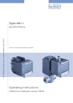
Type 8611
eCONTROL
Process controller
Prozessregler
Quickstart
We reserve the right to make technical changes without notice.
Technische Änderungen vorbehalten.
Sous resérve de modification techniques.
© 2008 Bürkert Werke GmbH & Co. KG
Operating Instructions 0810/00_EU-ML 00806149
Type 8611
Quickstart
Quickstart
Warning!
Important Safety Information!
Read Quickstart carefully and thoroughly. Study in particular the
chapters entitled General Safety Instructions and Intended Use.
• Quickstart must be read and understood.
Quickstart for the process controller eCONTROL 8611 explains, for
example, how to install and start-up the device.
A detailed description of the device can be found in the operating
instructions for the eCONTROL 8611. These instructions also include
the warranty provisions and details about the correct disposal of the
device.
The operating instructions can be found on the enclosed CD
and on the Internet at:
www.burkert.com → Documentation →
Operating Instructions → Type 8611
Symbols
The following symbols are used in these instructions.
Danger!
Warns of an immediate danger!
• Failure to observe the warning may result in a fatal or serious
injury.
Warning!
Warns of a potentially dangerous situation!
• Failure to observe the warning may result in a serious or fatal
injury.
Caution!
Warns of a possible danger!
• Failure to observe this warning may result in a medium or minor
injury.
Note!
Warns of damage to property!
Important tips and recommendations for safe and the flawless
functioning of the device.
→→designates a procedure which you must carry out.
English
3
Type 8611
Intended Use
Intended Use
Basic Safety Instructions
Non-intended use of the device can be dangerous to people,
nearby equipment and the environment.
• The eCONTROL 8611 is a process controller and may be used
to control temperature, pressure and flow-rate.
• Do not use the device outdoors.
• Use according to the authorized data, operating conditions and
conditions of use specified in the contract documents and operating instructions. These are described in the chapter entitled
Technical Data.
• The device may be used only in conjunction with third-party devices
and components recommended and authorized by Bürkert.
• Correct transportation, correct storage and installation and careful use and maintenance are essential for reliable and faultless
operation.
• Use the device only as intended.
4
English
These safety instructions do not make allowance for any
• contingencies and events which may arise during the installation,
operation and maintenance of the devices.
• local safety regulations – the operator is responsible for observing
these regulations, also with reference to the installation personnel.
General hazardous situations.
To prevent injury, ensure that:
• That the system cannot be activated unintentionally.
• Installation and repair work may be carried out by authorized
technicians only and with the appropriate tools.
• After an interruption in the power supply or pneumatic supply,
ensure that the process is restarted in a defined or controlled
manner.
• The device may be operated only when in perfect condition and
in consideration of the operating instructions.
• The general rules of technology apply to application planning and
operation of the device.
Type 8611
General Information
General Information
Note!
Electrostatic sensitive components / modules!
• The device contains electronic components which react sensitively
to electrostatic discharge (ESD). Contact with electrostatically
charged persons or objects is hazardous to these components.
In the worst case scenario, they will be destroyed immediately or
will fail after start-up.
• Observe the requirements in accordance with
DIN EN 61340-5-1/5-2 to minimise or avoid the possibility of
damage caused by sudden electrostatic discharge!
• Also ensure that you do not touch electronic components when
the power supply voltage is present!
The eCONTROL 8611 was developed with due consideration given to accepted safety rules and is state-of-the-art.
Nevertheless, dangerous situations may occur.
Failure to observe this operating manual and its operating instructions
as well as unauthorized tampering with the device release us from
any liability and also invalidate the guarantee covering the devices
and accessories!
Scope of Supply
Check immediately upon receipt of the delivery that the contents are
not damaged and that the type and scope agree with the delivery note
and packing list.
If there are any discrepancies, please contact us immediately.
Germany
Contact address:
Bürkert Fluid Control Systems
Sales Center
Chr.-Bürkert-Str. 13-17
D-74653 Ingelfingen
Tel. + 49 (0) 7940 - 10 111
Fax + 49 (0) 7940 - 10 448
E-mail: [email protected]
International
Contact addresses can be found on the final pages of these operating instructions.
And also on the internet at:
www.burkert.com
Bürkert
Company
English
Locations
5
Type 8611
Description of the Device
Guarantee
Description of the Device
This document contains no guarantees. Please refer to our general
terms of sales and delivery. The guarantee is only valid if the
eCONTROL 8611 is used as intended in accordance with the specified
application conditions.
Functions
The guarantee extends only to defects in the
eCONTROL 8611 and its components.
We accept no liability for any kind of collateral damage which
could occur due to failure or malfunction of the device.
The universal controller is linked to a control circuit. The position
set-point value of the valve is calculated from the process set-point
value and the process actual value via the control parameters
(PI controller). Electropneumatic valves (only in conjunction with a
control system), magnet control valves or electromotive valves can
be used as control valves.
4.3.Approvals
Technical Data
The approval rating on the Bürkert type plates refers to Bürkert
products.
Operating Conditions
Ambient temperature:
(operation and storage)
-20 ... +70 °C
4.4Information on the Internet
Relative humidity:
≤ 80 %, not condensed
The operating instructions and data sheets for Type 8611 can be found
on the Internet at:
Protection class:
IP65 to EN 60529
Documentation
manuals / data sheets
www.burkert.com
Type 8611
The complete operating instructions can be ordered on a CD by
quoting the following identification number: 00805612
6
English
Standard conformity CE:according to EMC Directive
EN50081.1
EN50082.2
Type 8611
Technical Data
General Technical Data
Inputs
Materials Housing, lid
Front plate film
Screws
Multipin
Wall-mounting holder
Set-point value
Standard 4 ... 20 mAMax. input impedance: 70 Ω
Resolution: 5.5 µA
PC, +20 % fibreglass
Polyester
Stainless steel
CuZn, nickel-plated
PVC
Installation:
Compact deviceAny installation position with
SO30 fitting
wall mounting
Hat-rail mounting
Display:
8-character LCD, 2 lines
Electrical connections:Multipin: 3-pin or / and
4-pin M8, 8-pin M12
Power cable:0.5 mm2 max. cross-section,
max. 100 m long,
screened
Electrical Data
Operating voltage:24 V DC ±10 %,
filtered and controlled
Standard 0 ... 10 VMax. input impedance: 11,5 kΩ
Resolution: 2.7 mV
Sensors
Standard 4 ... 20 mAMax. input impedance: 70 Ω
Resolution: 5.5 µA
Frequency
Input 1External Sensor
min: 0.25 Hz / max. 5 kHz
Input resistance: > 1kΩ
Signal types: Sine, rectangle,
triangle (> 3000 mVss, max. 30 Vss)
Input 2Internal Hall sensor
min: 0.25 Hz / max. 5 kHz
(only in conjunction with Bürkert
Type SO30 Flow-rate fitting)
Power consumption:
approx. 2 W (without valves)
Pt100 (2-wire)Measuring range: 0 °C ... 100 °C
Measured current: 1 mA
Measuring error: < 0.5 °C
Controller scanning rate:
300 Hz
Sensor supply
24 V DC, max. 1A
Binary input:Input impedance: 10 kΩ
Response threshold: 3 ... 30 V
Max. frequency: 5 kHz
English
7
Type 8611
Electrical Installation
Electrical Installation
Outputs
Continuous signalStandard signal 4 ... 20 mA
max. loop resistance: 680 Ω
Precision: 1 %
Discontinuous signal2 Transistor outputs (PNP) for PWM
signal
Control frequency: 1.2 kHz ... 20 Hz
Resolution max.: 16 Bit (frequencydependent) max. current per unit area: 2 A
Switching voltage: 24 V DC
Binary outputTransistor output (PNP) configurable
max. current per unit area: 2 A
Switching voltage: 24 V DC
Warning!
Risk of injury from incorrect installation!
Incorrect installation can damage or destroy the eCONTROL 8611.
• Installation may be carried out by authorized technicians only and
with the appropriate tools!
Pin assignment
Design versions
M12 8-pole
M12 8-pole
M12 8-pole
Total load for all outputs max. 2 A.
M8 3-pole
M8 4-pole
8
English
M8 4-pole
M8 3-pole
M8 4-pole
Type 8611
Electrical Installation
Connector diagrams
M12x1
8-pole
5
6
7
4
3
2
1
Connection power supply voltage,
set-point input, process actual value
or position set-point value output,
binary input, binary output
8
M8x1
3-pole
M8x1
4-pole
4
1
3
2
4
1
3
DIN-EN
175301
Sensor connection
(4 ... 20 mA, Pt100 or frequency)
Connection positioning device
• Proportional valve
• Process valve
Valve connection
2
1
Pin assignment
Wire colours when using standard cables (e.g. from Lumberg,
Escha)
Circular plug M12, 8-pole
Pin
Colour
Configuration
1
white
Operating voltage 24 V DC
2
Brown
Binary input 0 ... 30 V DC
3
green
GND - Operating voltage/binary input/binary
output
4
yellow
Analogue output (4 ... 20 mA)
(Process actual value or set-point value)
5
grey
Set-point value (+) (4 ... 20 mA)
6
pink
GND - Analogue output
7
blue
GND - set-point value (–)
8
red
Binary output (+)
English
9
Type 8611
Operation
Circular plug M8, 3-pole (sensor input)
Input type
Pin
Colour
4 ... 20 mA
2-wire
internally
supplied
1
3
Circular plug M8, 4-pole (set-point value output)
Configuration
Output type
Pin
Colour
Configuration
Brown
+ 24 V Transmitter supply
Brown
not used
not used
MODE=SCV
(Proportional valve)
1
blue
2
white
not used
4
black
Output Transmitter (4 ... 20 mA)
3
blue
PWM output (–)
4 ... 20 mA
3-wire
internally
supplied
1
Brown
+ 24 V Transmitter supply
4
black
PWM output (+)
1
Brown
Aaerate (+)
2
white
Aerate (–)
3
blue
Deaerate (–)
4
black
Deaerate (+)
Brown
+ 24 V supply
white
GND (4 ... 20 mA)
blue
GND (24 V)
black
+ 4 ... 20 mA
3
blue
GND
4
black
Output Transmitter (4 ... 20 mA)
4 ... 20 mA
4-wire
externally
supplied
1
Brown
not used
3
blue
GND
4
black
Output Transmitter (4 ... 20 mA)
Frequency
3-wire
internally
supplied
1
Brown
+ 24 V Transmitter supply
3
blue
GND
4
black
Frequency input (NPN)
Frequency
4-wire
externally
supplied
1
Brown
not used
3
blue
GND
4
black
Frequency input (NPN)
Pt100 2-wire
10
1
Brown
not used
3
blue
Process actual value GND
4
black
Process actual value
(power supply)
English
MODE=PCV
(Process valve)
Only for identification 1
number 182383
2
MODE = 4-20
3
(4-20 control)
4
Type 8611
Operation
Operation
Start-Up
Display elements
Operating states
The control and display element of the eCONTROL 8611 is
equipped with3 buttons and an LCD-Matrix display.
eCONTROL8611
025.5
L /M
The function of the buttons is described below.
ENTER
0..... 9
4-digit display shows process
and parameter variables
4-character text display shows,
for example, measuring units
and paramater names
10 Segment bar graph for analogue display of the position
set-point value in % (only in
MODE = SCV and 4 ... 20 mA)
Operator mode
O
u
t
ENTER
ENTER
Manual mode
>5
sec
Configuration mode
MODE
.
.
.
END
SET
PARA
VALV
ENTER
ENTER
ENTER button MANUAL/AUTOMATIC button
Red LED
Set-point value specification external
Control active/inactive
Manual mode
English
11
Type 8611
Start-Up
Display in operator mode
Configuration of the keys
050.5
Display process actual value
(unit analogous to UNIT)
050.0
Display set-point value
050.5
Display process actual value
°C
SET
Display set-point value
050.0
063.0
PRZ
1)
1)
Display set-point variable in percent or
4-20. Only for proportional valve
(MODE = SCV) or 4 ... 20 mA
positioning device (MODE = 4-20)
Only MODE = SCV or 4-20
12
English
Mode
To operate press button
Operator mode Switch display between
set-point value, actual
value and position setpoint value
Set set-point value
internally, manual
valve actuation
Configuration
mode or
manual mode
back in
menu
forwards in
menu
Enter menu item
Numeric input
Increase
value
one position Accept value
to the left
Type 8611
Start-Up
Operating structure in manual mode
ENTER
Set-point value specification
SET
ENTER
SET
ENTER
Enter set-point value
Return to operator mode
Adjustment control parameters
PARA
ENTER
KP 1
KP
2
TN
DEAD
ENTER
Control parameter KP1, KP2, TN and dead band can be optimized in the ongoing
process
Return to operator mode
Manual valve operation
VALV
ENTER
TEMP
FLOW
PRES
PRZ
Return to operator mode
continue
with TEST
0..... 9
ENTER
Open valve2)
(process value and/or positioning set-point are displayed)
Close valve2)
(process value and/or positioning set-point value are displayed)
MODE=4-20: The control of the valve is changed in steps of 0.2 mA per press of the button.
MODE=SCV: The control of the valve is changed by 1 % per press of the button.
MODE=PCV: The control is not displayed. Per press of the button, the aeration or bleed valve is actuated
for 40 ms.
2)
All MODES: If the button is pressed continuously > 80 ms, the control value is adjusted quickly.
English
13
Type 8611
Start-Up
Display Analogue Inputs/Outputs and Digital Inputs
0..... 9
TEST
ENTER
AIN1
Analogue input 1: Set-point value 4 ... 20 mA
AIN2
Analogue input 2: Set-point value 0 ... 10 V
AIN3
Analogue input 3: Sensor input 4 ... 20 mA
AIN4
Analogue input 4: Sensor input Pt100
DIN1
Digital input 1: Frequency input Hall sensor - internal
DIN2
Digital input 2: Frequency input - external
DIN3
Digital input 3: Binary input (> 3 V → Display 1,<3 V → Display 0)
AOUT
BACK
Return to operator mode
14
English
Analogue output 4-20 mA:
ENTER
Process actual value or set-point variable
Type 8611
Start-Up
Operating structure in configuration mode - overview
eCONTROL 8611
025.5
L /M
0..... 9
O
u
t
ENTER
> 5 sec
ENTER
MODE
0..... 9
Specify units, decimal point and display format
SETP
Select and scale set-point value specification
SCAL
Scale sensor input and sensor output
CALI
Calibrate analogue inputs and outputs
KFAC
Set K-factor
FILT
PARA
Set the filter of the sensor input
Specify control parameters
B IN
B_O1
Specify binary input
VALV
Valve test, adjustment Offset and CutOff
CODE
DSPL
Specify code protection
Activate background lighting
FACT
Return to delivery condition
XXXX
Display software implementation (e.g. U_01)
A XX
Return to operator mode
Select controlled variable, valve type and sensor input
UNIT
END
Specify binary output
Display software version (e.g. A_02)
ENTER
Accept set values
English
15
Type 8611
Start-Up
Select controlled variable, valve type and sensor input
> 5 sec
ENTER
MODE
Flow rate control
F
CODE 001
enter
Pressure control
P
ENTER
T+F
ENTER
Temperature control with flow-rate display
T- F
Temperature regulation
T
SCV
PCV
0..... 9
4 _ 20
ENTER
ENTER
4 _ 20
YES
no
2833
2834
2835
E_MS
B_MS
ENTER
ENTER
ENTER
Select proportional valve type or
input PWM frequency3)
Select process valve and
times for pilot valve4)
4 ... 20 mA positioning device
Sensor input - frequency
FREQ
PT
Temperature control with lower-level flow-rate control
ENTER
Sensor input - Pt100
Sensor input - 4 ... 20 mA
Save changes? (YES or no)
continue with UNIT
If the controlled variable (F, T, T-F, T+F, P) or the valve type (SCV, PCV, 4-20) changes, all parameters are reset to default values after
saving.
16
English
Type 8611
Start-Up
Select Proportional Valve and Select Control Frequency
3)
All Bürkert proportional valves are saved with the type number and can be selected. Deviating from this, however, freely selectable PWM
frequencies can be entered in the menu item FREE.
4)
Select Process Valve and Control Times for Pilot Valve
Process valves:
To operate process valves, a control block is needed for aerating and bleeding the drive
chamber.
Single, 2-x, 4-x and 6-x control blocks of the type 8810 are available as control valves.
Pilot valves:
A control time of 5 ms is needed for the type 8810 pilot valves. This is already stored in the
controller as a default value.
B_MS: Minimum control time for aeration valve in ms
E_MS: Minimum control time for bleed valve in ms
Figure: Control block 8810, single
English
17
Type 8611
Start-Up
Select units and nominal value specification
UNIT
ENTER
L/M
L/H
M3/H
ML/M
bar
Select unit
MODE = F:
MODE = P:
MODE = T:
MODE = T+F, T–F:
ENTER
1
0.1
0.01
ENTER
L/M, L/H, M3/H, ML/H, G/M, G/H
BAR, M BAR, PSI, NU
°C, °F
°C, °F, L/M, L/H, M3/H, ML/H, G/M, G/H
Select decimal point ( 1.0, 0.1, 0.01)
0..... 9
YES
no
ENTER
Display in % ? → YES or no
ENTER
SETP
INT
ENTER
EXHI
0..... 9
EXLO
ENTER
YES
no
DIRC
18
EXHI
English
Set-point value specification using keyboard and
scaling max. set-point value
Set-point value specification external (4-20 mA)
ENTER
EXT
ENTER
ENTER
ENTER
Scaling set-point value signal (EXHI, EXLO)
Effective direction between set-point value signal and process value
(no = direct, YES = inverted)
Type 8611
Start-Up
Scaling sensor input (4-20 mA), process value output (4-20 mA), calibration inputs-outputs,
input K-factor and select filter factor
Process value
input
S IN
SCAL
ENTER
0..... 9
Scaling sensor input signal
ENTER
4 MA
ENTER
Process value Select process variable*
output
ENTER
PRES
SOUT
TEMP
FLOW
20 MA
ENTER
Scaling process value
ENTER
4 MA
* Only available when MODE = T+F
ENTER
20MA
CALI
ENTER
Access code necessary
Calibration may be carried out only by trained personnel! (See Operating Instructions 8611)
0..... 9
Caution! When DP K=10 → Entered K-factor is multiplied by 10
KFAC
ENTER
0..... 9
FREE
S030
8011
8012
FILT
ENTER
02
04
06
08
10
ENTER
ENTER
ENTER
0.1
0.01
1
10
DN08
DN15
DN32
ENTER
KFAC
ENTER
ENTER
Input K-factor (freely selectable)
Select Buerkert sensor and
K-factor
Adjustment filter factor (2 ... 20)
English
19
Type 8611
Start-Up
Adjustment controller parameters
MODE = SCV
or 4-20
PARA
ENTER
KP1
Amplification factor – Scaling (% / PU)
TN
Reset time (in sec)
Dead band (absolute in selected unit UNIT)
DEAD
KP T
*)
TN T
*)
DE T
*)
INV
ZERO
Amplification factor cascaded temperature control (∆T / ∆Q)
ENTER
Reset time cascaded temperature control (in sec)
Dead band cascaded temperature control (absolute in °C)
Effective direction between sensor input signal and valve position (YES = inverted)
Zero point shut off at set-point value < 2% (only available when INV=no)
*) Only available when MODE = T+F
continue with B IN
20
English
Type 8611
Start-Up
MODE = PCV
PARA
ENTER
KP1
Amplification factor – aerate/open valve (scaling in sec/PU)
KP2
Amplification factor – bleed/close valve (scaling in sec/PU)
Cycle time for set-point value/actual value - comparison in sec
TREG
Dead band (absolute in selected unit - UNIT)
DEAD
ENTER
KP T
*)
Amplification factor cascaded temperature control (scaling ∆T / ∆Q)
TN T
*)
Reset time cascaded temperature control (in sec)
DE T
*)
Dead band cascaded temperature control (absolute in °C)
0..... 9
INV
ZERO
Effective direction between process value and valve position (YES = inverted)
Zero point shut off at set-point value < 2% (only available when INV=no)
*) Only available when MODE = T+F
continue with B_01
English
21
Type 8611
Start-Up
Adjustment binary input
0..... 9
B IN
ENTER
no
YES
STOP
CLOS
CTRL
continue with B_01
22
English
ENTER
ENTER
Binary input deactivated
HIGH
ENTER
Binary input active, when input voltage level < 3 VDC
LOW
ENTER
OPEN
CLOS
ENTER
Binary input active,
when input voltage level 3 ... 30 VDC
ENTER
Valve stops opening movement (only MODE = PCV)
Valve stops closing movement (only MODE = PCV)
Valve closes
Controller deactivated, valve remains in the last position
Type 8611
Start-Up
Adjustment binary output as alarm function
0..... 9
B_O1
YES
no
ENTER
2-P
ALRM
SETP
FLOW
PRES
TEMP
Lower hysteresis
HYLO
ENTER
Delay time
DLY
Activation binary output
ENTER
ENTER
Alarm function
ENTER
Monitoring relative to set-point value
ENTER
Monitoring relative to process value limits
Upper hysteresis
ENTER
Lower limit
PVLO
ENTER
ENTER
HYHI
Upper limit
PVHI
HIGH
LOW
ENTER
ENTER
ENTER
HIGH: Output active at 24 V
LOW: Output active at 0 V
continue with VALV
English
23
Type 8611
Start-Up
Adjustment binary output as 2-point controller
0..... 9
B_O1
YES
no
ENTER
2-P
ALRM
SETP
FLOW
PRES
TEMP
Lower hysteresis
HYLO
ENTER
Delay time
DLY
ENTER
continue with VALV
24
Activation binary output
ENTER
2-point control function
ENTER
ENTER
Control relative to set-point value
ENTER
Control relative to process value limits
Upper hysteresis
ENTER
Lower limit
PVLO
ENTER
English
HYHI
Upper limit
PVHI
YES
no
ENTER
ENTER
ENTER
Effective direction between sensor signal and valve movement
YES:Inverted control
no: Direct control
HIGH
LOW
ENTER
HIGH: Output active at 24 V
LOW: Output active at 0 V
Type 8611
Start-Up
Valve test and adjustment control area
0..... 9
VALV
TEMP
FLOW
100
PRZ
ENTER
END
MIN
MAX
ENTER
Open valve5)
process value and/or positioning set-point are displayed
0..... 9
ENTER
Close valve5)
process value and/or positioning set-point value are displayed
END - Return without saving
MIN - Set-point variable or process value is saved as MIN value
MAX- Set-point variable or process value is saved as MAX value
continue with CODE
MODE=4-20: The control of the valve is changed in steps of 0.2 mA per press of the button.
MODE=SCV: The control of the valve is changed by 1 % per press of the button.
MODE=PCV: The control is not displayed. Per press of the button, the aeration or bleed valve is actuated
for 40 ms.
5)
All MODES: If the button is pressed continuously > 80 ms, the control value is adjusted quickly.
English
25
Type 8611
Start-Up
CODE protection, background illumination, program version
0..... 9
CODE
ENTER
XXXX
ENTER
CODE 0000 - Code protection not activated
CODE xxxx -Code protection activated, code is requested when entering
configuration level
Deactivate background lighting?
DSPL
ENTER
YES
no
ENTER
YES:Deactivated, lighting switches on when button is pressed and is
switched off after 1 min if not pressed
no:
DSPL
FACT
YES
no
ENTER
YES:Return to delivery condition
no:
Return without saving
U_01
Display program version
A _xx
Display software version
END
26
ENTER
Activated, lighting switched on continuously
ENTER
Return to operator mode
English
Type 8611
Packaging and Transport
Packaging and Transport
Note!
Transport damages!
Inadequately protected equipment may be damaged during
transport.
• During transportation protect the device against wet and dirt in
shock-resistant packaging.
• Avoid exceeding or dropping below the allowable storage
temperature.
Disposal
→→Dispose of the device and packaging in an environmentally friendly
manner.
Note!
Damage to the environment caused by device components
contaminated with media.
• Observe applicable regulations on disposal and the
environment.
• Observe national waste disposal regulations.
Storage
Note!
Incorrect storage may damage the device.
• Store the device in a dry and dust-free location!
• Storage temperature. -20 …+ 70 °C.
English
27
Type 8611

28
English
Typ 8611
Der Quickstart
Der Quickstart
Warnung!
Wichtige Informationen zur Sicherheit!
Lesen Sie den Quickstart sorgfältig durch. Beachten Sie vor allem die
Kapitel Allgemeine Sicherheitshinweise und Bestimmungsgemäße
Verwendung.
• Der Quickstart muss gelesen und verstanden werden.
Der Quickstart für den Prozessregler eCONTROL 8611 erläutert
beispielhaft die Montage und Inbetriebnahme des Gerätes.
Die ausführliche Beschreibung des Gerätes finden Sie in der Bedienungsanleitung des eCONTROL 8611. Diese enthält auch die Garantiebestimmungen, sowie die Angaben zur sachgerechten Entsorgung
des Gerätes.
Die Bedienungsanleitung finden Sie auf der beigelegten CD
oder im Internet unter:
www.buerkert.de → Dokumentation →
Bedienungsanleitungen → Typ 8611
Darstellungsmittel
In dieser Anleitung werden folgende Darstellungsmittel verwendet.
Gefahr!
Warnt vor einer unmittelbaren Gefahr!
• Bei Nichtbeachtung sind Tod oder schwere Verletzungen die
Folge.
Warnung!
Warnt vor einer möglicherweise gefährlichen Situation!
• Bei Nichtbeachtung können schwere Verletzungen oder Tod die
Folge sein.
Vorsicht!
Warnt vor einer möglichen Gefährdung!
• Nichtbeachtung kann mittelschwere oder leichte Verletzungen
zur Folge haben.
Hinweis!
Warnt vor Sachschäden!
Wichtige Tipps und Empfehlungen für die Sicherheit und
einwandfreie Funktion des Gerätes.
→→markiert einen Arbeitsschritt den Sie ausführen müssen.
deutsch
29
Typ 8611
Bestimmungsgemässe Verwendung
Bestimmungsgemässe
Verwendung
Grundlegende
Sicherheitshinweise
Bei nicht bestimmungsgemäßem Einsatz des Gerätes können
Gefahren für Personen, Anlagen in der Umgebung und die
Umwelt entstehehen.
• Der eCONTROL 8611 ist ein Prozessregler und darf zur Regelung von Temperatur, Druck und Durchfluss eingesetzt werden.
• Das Gerät nicht im Außenbereich einsetzen.
• Für den Einsatz die in den Vertragsdokumenten und der Bedienungsanleitung spezifizierten zulässigen Daten, Betriebs- und
Einsatzbedingungen beachten. Diese sind im Kapitel Technische
Daten beschrieben.
• Das Gerät nur in Verbindung mit von Bürkert empfohlenen bzw.
zugelassenen Fremdgeräten und -komponenten einsetzen.
• Voraussetzungen für den sicheren und einwandfreien Betrieb sind
sachgemäßer Transport, sachgemäße Lagerung und Installation
sowie sorgfältige Bedienung und Instandhaltung.
• Setzen Sie das Gerät nur bestimmungsgemäß ein.
30
deutsch
Diese Sicherheitshinweise berücksichtigen keine
• Zufälligkeiten und Ereignisse, die bei Montage, Betrieb und
Wartung der Geräte auftreten können.
• ortsbezogenen Sicherheitsbestimmungen, für deren Einhaltung,
auch in Bezug auf das Montagepersonal, der Betreiber verantwortlich ist.
Allgemeine Gefahrensituationen.
Zum Schutz vor Verletzungen ist zu beachten:
• Dass die Anlage nicht unbeabsichtigt betätigt werden kann.
• Installations- und Instandhaltungsarbeiten dürfen nur von autorisiertem Fachpersonal mit geeignetem Werkzeug ausgeführt
werden.
• Nach einer Unterbrechung der elektrischen oder pneumatischen
Versorgung ist ein definierter oder kontrollierter Wiederanlauf des
Prozesses zu gewährleisten.
• Das Gerät darf nur in einwandfreiem Zustand und unter Beachtung
der Bedienungsanleitung betrieben werden.
• Für die Einsatzplanung und den Betrieb des Gerätes müssen die
allgemeinen Regeln der Technik eingehalten werden.
Typ 8611
Allgemeine Hinweise
Hinweis!
Elektrostatisch gefährdete Bauelemente / Baugruppen!
• Das Gerät enthält elektronische Bauelemente, die gegen elektrostatische Entladung (ESD) empfindlich reagieren. Berührung
mit elektrostatisch aufgeladenen Personen oder Gegenständen
gefährdet diese Bauelemente. Im schlimmsten Fall werden sie
sofort zerstört oder fallen nach der Inbetriebnahme aus.
• Beachten Sie die Anforderungen nach DIN EN 61340-5-1 / 5-2,
um die Möglichkeit eines Schadens durch schlagartige elektrostatische Entladung zu minimieren bzw. zu vermeiden!
• Achten Sie ebenso darauf, dass Sie elektronische Bauelemente
nicht bei anliegender Versorgungsspannung berühren!
Der eCONTROL 8611wurde unter Einbeziehung der anerkannten sicherheitstechnischen Regeln entwickelt und entspricht dem Stand der Technik. Trotzdem können Gefahren
entstehen.
Bei Nichtbeachtung dieser Bedienungsanleitung und ihrer Hinweise
sowie bei unzulässigen Eingriffen in das Gerät entfällt jegliche Haftung unsererseits, ebenso erlischt die Gewährleistung auf Geräte
und Zubehörteile!
Allgemeine Hinweise
Lieferumfang
Überzeugen Sie sich unmittelbar nach Erhalt der Sendung, dass der
Inhalt nicht beschädigt ist und in Art und Umfang mit dem Lieferschein
bzw. der Packliste übereinstimmt.
Bei Unstimmigkeiten wenden Sie sich bitte umgehend an uns.
Deutschland
Kontaktadresse:
Bürkert Fluid Control Systems
Sales Center
Chr.-Bürkert-Str. 13-17
D-74653 Ingelfingen
Tel. + 49 (0) 7940 - 10 111
Fax + 49 (0) 7940 - 10 448
E-mail: [email protected]
International
Die Kontaktadressen finden Sie auf den letzten Seiten dieser
Bedienungsanleitung.
Außerdem im Internet unter:
www.burkert.com
deutsch
Bürkert
Company
Locations
31
Typ 8611
Gerätebeschreibung
Gewährleistung
Gerätebeschreibung
Diese Druckschrift enthält keine Garantiezusagen. Wir verweisen
hierzu auf unsere allgemeinen Verkaufs- und Lieferbedingungen.
Voraussetzung für die Gewährleistung ist der bestimmungsgemäße
Gebrauch des eCONTROL 8611 unter Beachtung der spezifizierten
Einsatzbedingungen.
Funktionen
Die Gewährleistung erstreckt sich nur auf die Fehlerfreiheit
des eCONTROL 8611 und seiner Bauteile.
Für Folgeschäden jeglicher Art, die durch Ausfall oder Fehlfunktion des Gerätes entstehen könnten, wird keine Haftung
übernommen.
Der Universalregler ist in einen Regelkreis eingebunden. Aus dem
Prozess-Sollwert und dem Prozess-Istwert errechnet sich über die
Regelparameter (PI-Regler) die Stellgröße des Ventils. Als Regelventile können elektropneumatische Ventile (nur in Verbindung mit
einem Stellsystem), Magnetregelventile oder elektromotorische
Ventile eingesetzt werden.
Technische Daten
4.3Zulassungen
Betriebsbedingungen
Die auf den Bürkert Typschildern aufgebrachte
Zulassungskennzeichnung bezieht sich auf die Bürkert Produkte.
Umgebungstemperatur:
(Betrieb und Lagerung)
-20 ... +70 °C
Relative Feuchtigkeit:
≤ 80 %, nicht kondensiert
Schutzart:
IP65 nach EN 60529
4.4Informationen im Internet
Bedienungsanleitungen und Datenblätter zum Typ 8611 finden Sie
im Internet unter:
Technische Daten
Betriebsanleitung /
www.buerkert.de
Datenblätter
Typ 8611
Die komplette Bedienungsanleitung können Sie als CD unter folgender Identnummer bestellen: 00805612
32
deutsch
Normenkonformität CE:gemäß EMV-Richtlinie
EN50081.1
EN50082.2
Typ 8611
Technische Daten
Allgemeine technische Daten
Eingänge
Werkstoffe:
Gehäuse, Deckel
Frontplattenfolie
Schrauben
Multipin
Wandmontagehalter
Sollwert
Norm 4 ... 20 mAMax. Eingangsimpedanz: 70 Ω
Auflösung: 5,5 µA
PC, +20 % Glasfaser
Polyester
Edelstahl
CuZn, vernickelt
PVC
Montage:
KompaktgerätEinbaulage beliebig mit
Fitting SO30
Wandmontage
Hutschienenmontage
Anzeige:
8-Zeichen LCD, 2-zeilig
Elektrische Anschlüsse:Multipin: 3-Pin oder / und
4-Pin M8, 8-Pin M12
Stromzuleitungskabel:0,5 mm2 max. Querschnitt,
max. 100 m lang,
abgeschirmt
Elektrische Daten
Norm 0 ... 10 VMax. Eingangsimpedanz: 11,5 kΩ
Auflösung: 2,7 mV
Sensoren
Norm 4 ... 20 mAMax. Eingangsimpedanz: 70 Ω
Auflösung: 5,5 µA
Frequenz
Eingang 1Extern-Sensor
min: 0,25 Hz / max. 5 kHz
Eingangswiderstand: > 1kΩ
Signalarten: Sinus, Rechteck,
Dreieck (> 3000 mVss, max. 30 Vss)
Eingang 2Intern Hall-Sensor
min: 0,25 Hz / max. 5 kHz
(nur in Verbindung mit Bürkert
Typ SO30 Durchfluss-Fitting)
Betriebsspannung:24 V DC ±10 %,
gefiltert und geregelt
Pt100 (2-Leiter)Messbereich: 0 °C ... 100 °C
Messstromstärke: 1 mA
Messfehler: < 0,5 °C
Leistungsaufnahme:
ca. 2 W (ohne Ventile)
Sensorversorgung
Regler Abtastrate:
300 Hz
24 V DC, max. 1A
Binäreingang:Eingangsimpedanz: 10 kΩ
Ansprechschwelle: 3 ... 30 V
Max. Frequenz: 5 kHz
deutsch
33
Typ 8611
Elektrische Installation
Elektrische Installation
Ausgänge
Stetiges SignalNormsignal 4 ... 20 mA
max. Schleifenwiderstand: 680 Ω
Genauigkeit: 1 %
Unstetiges Signal2 Transistorausgänge (PNP) für PWMSignal
Ansteuerfrequenz: 1,2 kHz ... 20 Hz
Auflösung max.: 16 Bit (frequenzabhängig)
max.Strombelastung: 2 A
Schaltspannung: 24 V DC
BinärausgangTransistorausgang (PNP) konfigurierbar
max. Strombelastung: 2 A
Schaltspannung: 24 V DC
Warnung!
Verletzungsgefahr bei fehlerhafter Installation!
Unsachgemäße Installation kann den eCONTROL 8611 beschädigen oder zerstören.
• Die Installation darf nur autorisiertes Fachpersonal mit geeignetem
Werkzeug durchführen!
Anschlussbelegung
Ausführungsvarianten
M12 8-polig
Summenbelastung für alle Ausgänge max. 2 A.
M12 8-polig
M8 3-polig
M8 4-polig
34
deutsch
M8 4-polig
M12 8-polig
M8 3-polig
M8 4-polig
Typ 8611
Elektrische Installation
Steckerbilder
M12x1
8-polig
1
M8x1
3-polig
M8x1
4-polig
5
6
7
Anschlussbelegung
4
3
2
8
4
1
3
2
4
1
3
DIN-EN
175301
Anschluss Versorgungsspannung,
Sollwerteingang, ProzessIstwert- oder Stellgrößenausgang,
Binäreingang, Binärausgang
Anschluss Sensor
(4 ... 20 mA, Pt100 oder Frequenz)
Anschluss Stellgerät
• Proportionalventil
• Prozessventil
Anschluss Ventil
2
1
Adernfarben bei Verwendung von Standardkabeln (z. B. von
Fa. Lumberg, Escha)
Rundstecker M12, 8-polig
Pin
Farbe
Belegung
1
weiß
Betriebsspannung 24 V DC
2
braun
Binäreingang 0 ... 30 V DC
3
grün
GND - Betriebsspannung / Binäreingang /
Binärausgang
4
gelb
Analogausgang (4 ... 20 mA)
(Prozess-Istwert oder Stellgröße)
5
grau
Sollwert (+) (4 ... 20 mA)
6
rosa
GND - Analogausgang
7
blau
GND - Sollwert (–)
8
rot
Binärausgang (+)
deutsch
35
Typ 8611
Bedienung
Rundstecker M8, 3-polig (Sensoreingang)
Eingangstyp
Pin
Farbe
Rundstecker M8, 4-polig (Stellgrößenausgang)
Belegung
Ausgangstyp
Pin
Farbe
Belegung
MODE=SCV
(Proportionalventil)
1
braun
nicht belegt
2
weiß
nicht belegt
3
blau
PWM Ausgang (–)
4 ... 20 mA
1
2-Leiter Intern 3
versorgt
4
braun
+ 24 V Versorgung Transmitter
blau
nicht belegt
4 ... 20 mA
1
3-Leiter Intern 3
versorgt
4
braun
+ 24 V Versorgung Transmitter
blau
GND
1
braun
3
blau
4
schwarz Ausgang Transmitter (4 ... 20 mA)
4 ... 20 mA
4-Leiter
Extern
versorgt
schwarz Ausgang Transmitter (4 ... 20 mA)
4
schwarz PWM Ausgang (+)
1
braun
Belüften (+)
2
weiß
Belüften (–)
nicht belegt
3
blau
Entlüften (–)
GND
4
schwarz Entlüften (+)
Nur für Identnummer
182383
1
braun
+ 24 V Versorgung
2
weiß
GND (4 ... 20 mA)
MODE = 4-20
(4-20 Ansteuerung)
3
blau
GND (24 V)
4
schwarz + 4 ... 20 mA
schwarz Ausgang Transmitter (4 ... 20 mA)
Frequenz
1
3-Leiter Intern 3
versorgt
4
braun
+ 24 V Versorgung Transmitter
blau
GND
Frequenz
4-Leiter
Extern
versorgt
1
braun
nicht belegt
3
blau
GND
4
schwarz Frequenz-Eingang (NPN)
Pt100
2-Leiter
1
braun
nicht belegt
3
blau
Prozess-Ist GND
4
schwarz Prozess-Ist (Stromspeisung)
36
schwarz Frequenz-Eingang (NPN)
deutsch
MODE=PCV
(Prozessventil)
Typ 8611
Bedienung
Bedienung
Inbetriebnahme
Anzeigeelemente
Betriebszustände
Das Bedien- und Anzeigeelement des eCONTROL 8611 ist mit
3 Tasten und einer LCD-Matrix-Anzeige ausgestattet.
eCONTROL8611
025.5
L /M
Die Funktion der Tasten ist nachfolgend beschrieben.
0..... 9
O
u
t
ENTER
4-stellige Anzeige zeigt
Prozess- und Parametergrößen
4-stellige Textanzeige zeigt z. B.
Messeinheiten und
Parameterbezeichnungen
10-Segment-Bargraph für die
analoge Anzeige der Stellgröße
in % (nur bei MODE = SCV
und 4 ... 20 mA)
Bedienermodus
ENTER
Handmodus
ENTER
>5
sec
Konfigurationsmodus
MODE
.
.
.
END
SET
PARA
VALV
ENTER
ENTER
ENTER-Taste
HAND/AUTOMATIK-Taste
Rote LED
Sollwertvorgabe extern
Regelung aktiv / inaktiv
Handmodus
deutsch
37
Typ 8611
Inbetriebnahme
Anzeige im Bedienermodus
050.5
Anzeige Prozess-Istwert
(Einheit analog UNIT)
050.0
Anzeige Sollwert
050.5
Anzeige Prozess-Istwert
°C
Belegung der Tasten
Modus
SET
050.0
063.0
PRZ
1)
1)
Anzeige Sollwert
Bedienermodus Anzeige Umschalten
zwischen Sollwert, Istwert
und Stellgröße
Anzeige Stellgröße in PRZ oder 4-20. Nur
für Proportionalventil (MODE = SCV) oder
4 ... 20 mA Stellgerät (MODE = 4-20)
Konfigurations- im Menü
Modus oder
zurück
Handmodus
im Menü vor Einstieg in
Menüpunkt
Zahleneingabe
eine Stelle
nach links
Nur MODE = SCV oder 4-20
38
Zur Betätigung Taste drücken
deutsch
Wert
erhöhen
Einstellung Sollwert
intern. Manuelle
Ventilbetätigung
Wert übernehmen
Typ 8611
Inbetriebnahme
Bedienstruktur im Handmodus
ENTER
Sollwertvorgabe
SET
ENTER
SET
ENTER
Eingabe Sollwert
Rücksprung in Bedienermodus
Einstellung Regelparameter
PARA
ENTER
KP 1
KP
2
TN
DEAD
ENTER
Regelparameter KP1, KP2, TN und Totband können bei laufendem Prozess
optimiert werden
Rücksprung in Bedienermodus
Manuelle Ventilbetätigung
VALV
ENTER
TEMP
FLOW
PRES
PRZ
Rücksprung in Bedienermodus
weiter mit
TEST
0..... 9
ENTER
Ventil öffnen 2)
(Prozesswert und/oder Stellgröße werden angezeigt)
Ventil schließen 2)
(Prozesswert und/oder Stellgröße werden angezeigt)
MODE=4-20: Die Ansteuerung des Ventils wird je Tastendruck in Schritten von 0,2 mA geändert.
MODE=SCV: Die Ansteuerung des Ventils wird je Tastendruck um 1 % geändert.
MODE=PCV: Die Ansteuerung wird nicht angezeigt. Je Tastendruck wird das Belüftungs- oder Entlüftungsventil für
40 ms betätigt.
2)
Alle MODI: Bei kontinuierlichem Tastendruck > 80 ms erfolgt Schnellverstellung des Ansteuerwertes.
deutsch
39
Typ 8611
Inbetriebnahme
Anzeige analoge Ein-/Ausgänge und digitale Eingänge
0..... 9
TEST
ENTER
AIN1
Analogeingang 1: Sollwert 4 ... 20 mA
AIN2
Analogeingang 2: Sollwert 0 ... 10 V
AIN3
Analogeingang 3: Sensoreingang 4 ... 20 mA
AIN4
Analogeingang 4: Sensoreingang Pt100
DIN1
Digitaleingang 1: Frequenzeingang Hallsensor - intern
DIN2
Digitaleingang 2: Frequenzeingang - extern
DIN3
Digitaleingang 3: Binäreingang (> 3 V → Anzeige 1,<3 V → Anzeige 0)
AOUT
BACK
Analogausgang 4-20 mA: Prozess-Istwert oder Stellgröße
ENTER
Rücksprung in Bedienermodus
40
deutsch
Typ 8611
Inbetriebnahme
Bedienstruktur im Konfigurationsmodus - Übersicht
eCONTROL 8611
025.5
L /M
0..... 9
O
u
t
ENTER
> 5 sec
ENTER
MODE
0..... 9
Einheiten, Dezimalpunkt und Anzeigeformat festlegen
SETP
Sollwertvorgabe auswählen und skalieren
SCAL
Sensoreingang und Sensorausgang skalieren
CALI
Analoge Ein- und Ausgänge kalibrieren
KFAC
K-Faktor einstellen
FILT
PARA
Filter des Sensoreingangs einstellen
Regelparameter festlegen
B IN
B_O1
Binäreingang festlegen
VALV
Ventiltest, Einstellung Offset und CutOff
CODE
DSPL
Codeschutz festlegen
Hintergrundbeleuchtung aktivieren
FACT
Zurücksetzen in Auslieferungszustand
XXXX
Anzeige Softwareausführung (z. B. U_01)
A XX
Zurück zu
Bedienermodus
Auswahl Regelgröße, Ventiltyp und Sensoreingang
UNIT
END
Binärausgang festlegen
Anzeige Softwareverson (z. B. A_02)
ENTER
Eingestellte Werte übernehmen
deutsch
41
Typ 8611
Inbetriebnahme
Auswahl Regelgröße, Ventiltyp und Sensoreingang
> 5 sec
ENTER
MODE
Durchflussregelung
F
CODE 001
eingeben
Druckregelung
P
ENTER
T+F
ENTER
Temperaturregelung mit Durchflussanzeige
T- F
Temperaturregelung
T
SCV
PCV
0..... 9
4 _ 20
ENTER
ENTER
PT
2833
2834
2835
E_MS
B_MS
ENTER
ENTER
ENTER
Auswahl Proportionalventil Typ oder
Eingabe PWM-Frequenz 3)
Auswahl Prozessventil und
Zeiten für Pilotventil 4)
4 ... 20 mA Stellgerät
Sensoreingang - Frequenz
FREQ
ENTER
4 _ 20
YES
no
Temperaturregelung mit unterlagerter Durchflussregelung
Sensoreingang - Pt100
Sensoreingang - 4 ... 20 mA
Änderungen speichern? (YES oder no)
weiter mit UNIT
Bei Änderung der Regelgröße (F, T, T-F, T+F, P) oder des Ventiltyps (SCV, PCV, 4-20) erfolgt die Rücksetzung aller Parameter auf
Defaultwerte nach dem Abspeichern.
42
deutsch
Typ 8611
Inbetriebnahme
Auswahl Proportionalventil und Auswahl Ansteuerfrequenz
3)
Alle Bürkert Proportionalventile sind mit Typnummer abgespeichert und können ausgewählt werden. Davon abweichend können aber auch
unter dem Menüpunkt FREE frei wählbare PWM-Frequenzen eingegeben werden.
4)
Auswahl Prozessventil und Ansteuerzeiten für Pilotventil
Prozessventile:
Für das Betreiben von Prozessventilen wird zur Ansteuerung ein Ansteuerblock zum Belüften und
Entlüften der Antriebskammer benötigt.
Als Ansteuerventile stehen 1-fach, 2-fach, 4-fach und 6-fach Ansteuerblöcke vom Typ 8810 zur
Verfügung.
Pilotventile:
Für die Pilotventile vom Typ 8810 wird eine Ansteuerzeit von 5 ms benötigt. Dies ist als
Defaultwert bereits im Controller hinterlegt.
B_MS: Minimale Ansteuerzeit für Belüftungsventil in ms
E_MS: Minimale Ansteuerzeit für Entlüftungsventil in ms
Bild: Ansteuerblock 8810, 1-fach
deutsch
43
Typ 8611
Inbetriebnahme
Auswahl Einheiten und Sollwertvorgabe
UNIT
ENTER
L/M
L/H
M3/H
ML/M
bar
Auswahl Einheit
MODE = F:
MODE = P:
MODE = T:
MODE = T+F, T–F:
ENTER
1
0.1
0.01
ENTER
L/M, L/H, M3/H, ML/H, G/M, G/H
BAR, M BAR, PSI, NU
°C, °F
°C, °F, L/M, L/H, M3/H, ML/H, G/M, G/H
Auswahl Dezimalpunkt ( 1.0, 0.1, 0.01)
0..... 9
YES
no
ENTER
Anzeige in % ? → YES or no
ENTER
SETP
INT
ENTER
EXHI
0..... 9
EXLO
DIRC
44
ENTER
EXHI
YES
no
Sollwertvorgabe über Tastatur und
Skalierung max. Sollwert
Sollwertvorgabe extern (4-20 mA)
ENTER
EXT
ENTER
ENTER
ENTER
deutsch
Skalierung Sollwertsignal (EXHI, EXLO)
Wirksinn zwischen Sollwertsignal und Prozesswert
(no = Direkt, YES = Invertiert)
Typ 8611
Inbetriebnahme
Skalierung Sensoreingang (4-20 mA), Prozesswertausgang (4-20 mA), Kalibrierung EinAusgänge, Eingabe K-Faktor und Auswahl Filterfaktor
ProzesswertEingang
S IN
SCAL
ENTER
0..... 9
Skalierung Sensor Eingangssignal
ENTER
ProzesswertAusgang
SOUT
4 MA
Auswahl Prozessgröße*
ENTER
PRES
TEMP
FLOW
ENTER
20 MA
ENTER
Skalierung Prozesswert
ENTER
4 MA
* Nur bei MODE T-F oder T+F
ENTER
20MA
CALI
ENTER
Zugangscode erforderlich
Kalibrierung darf nur von geschultem Personal durchgeführt werden! (Siehe Bedienungsanleitung 8611)
0..... 9
Achtung! Bei DP K=10 → Eingegebener K-Faktor wird mit 10 multipliziert
KFAC
ENTER
0..... 9
FREE
S030
8011
8012
FILT
ENTER
02
04
06
08
10
ENTER
ENTER
ENTER
0.1
0.01
1
10
DN08
DN15
DN32
ENTER
KFAC
ENTER
ENTER
Eingabe K-Faktor (frei wählbar)
Auswahl Buerkert Sensor und
K-Faktor
Einstellung Filterfaktor (2 ... 20)
deutsch
45
Typ 8611
Inbetriebnahme
Einstellung Reglerparameter
MODE = SCV
oder 4-20
PARA
ENTER
KP1
Verstärkungsfaktor – Skalierung (% / PU)
TN
Nachstellzeit (in sec)
Totband (absolut in gewählter Einheit UNIT)
DEAD
KP T
*)
TN T
*)
DE T
*)
INV
ZERO
Verstärkungsfaktor kaskadierte Temperaturregelung (∆T / ∆Q)
ENTER
Nachstellzeit kaskadierte Temperaturregelung (in sec)
Totband kaskadierte Temperaturregelung (absolut in °C)
Wirksinn zwischen Sensoreingangssignal und Ventilstellung (YES = invertiert)
Nullpunktabschaltung bei Sollwert < 2% (nur verfügbar bei INV=no)
*) Nur verfügbar bei MODE = T+F
weiter mit B IN
46
deutsch
Typ 8611
Inbetriebnahme
MODE = PCV
PARA
ENTER
KP1
Verstärkungsfaktor – Ventil belüften/öffnen (Skalierung in sec / PU)
KP2
Verstärkungsfaktor – Ventil entlüften/schließen (Skalierung in sec / PU)
Zykluszeit für Sollwert/Istwert – Vergleich in sec
TREG
Totband (absolut in gewählter Einheit – UNIT)
DEAD
ENTER
KP T
*)
Verstärkungsfaktor kaskadierte Temperaturregelung (Skalierung ∆T / ∆Q)
TN T
*)
Nachstellzeit kaskadierte Temperaturregelung (in sec)
DE T
*)
Totband kaskadierte Temperaturregelung (absolut in °C)
0..... 9
INV
Wirksinn zwischen Prozesswert und Ventilstellung (YES = Invertiert)
ZERO
Nullpunktabschaltung bei Sollwert < 2% (nur verfügbar bei INV=no)
*) Nur verfügbar bei MODE = T+F
weiter mit B IN
deutsch
47
Typ 8611
Inbetriebnahme
Einstellung Binäreingang
0..... 9
B IN
ENTER
no
YES
STOP
CLOS
ENTER
ENTER
Binäreingang deaktiviert
HIGH
ENTER
OPEN
CLOS
Binäreingang aktiv,
wenn Eingangs-Spannungspegel 3 ... 30 VDC
Binäreingang aktiv,
wenn Eingangs-Spannungspegel < 3 VDC
LOW
ENTER
Ventil stoppt Öffnungsbewegung (nur MODE = PCV)
Ventil stoppt Schließbewegung (nur MODE = PCV)
Ventil schließt
ENTER
Regler deaktiviert, Ventil bleibt in der letzten Stellung
CTRL
weiter mit B_01
48
ENTER
deutsch
Typ 8611
Inbetriebnahme
Einstellung Binärausgang als Alarmfunktion
0..... 9
B_O1
YES
no
ENTER
2-P
ALRM
SETP
FLOW
PRES
TEMP
Untere Hysterese
HYLO
ENTER
Verzögerungszeit
DLY
Aktivierung Binärausgang
ENTER
ENTER
Alarmfunktion
ENTER
Überwachung relativ zu Sollwert
ENTER
Überwachung relativ zu Prozesswertgrenzen
Obere Hysterese
ENTER
Untere Grenze
PVLO
ENTER
ENTER
HYHI
Obere Grenze
PVHI
HIGH
LOW
ENTER
ENTER
ENTER
HIGH: Ausgang aktiv bei 24 V
LOW: Ausgang aktiv bei 0 V
weiter mit VALV
deutsch
49
Typ 8611
Inbetriebnahme
Einstellung Binärausgang als 2-Punkt-Regler
0..... 9
B_O1
YES
no
ENTER
2-P
ALRM
SETP
FLOW
PRES
TEMP
Untere Hysterese
HYLO
ENTER
Verzögerungszeit
DLY
Aktivierung Binärausgang
ENTER
2-Punkt Regelfunktion
ENTER
ENTER
Regelung relativ zu Sollwert
ENTER
Regelung relativ zu Prozesswertgrenzen
Obere Hysterese
ENTER
Untere Grenze
PVLO
ENTER
ENTER
HYHI
Obere Grenze
PVHI
YES
no
ENTER
ENTER
ENTER
weiter mit VALV
50
deutsch
Wirksinn zwischen Sensorsignal und Ventilbewegung
YES:Invertierte Regelung
no: Direkte Regelung
HIGH
LOW
ENTER
HIGH: Ausgang aktiv bei 24 V
LOW: Ausgang aktiv bei 0 V
Typ 8611
Inbetriebnahme
Ventiltest und Einstellung Regelbereich
0..... 9
VALV
TEMP
FLOW
100
PRZ
ENTER
END
MIN
MAX
ENTER
Ventil öffnen 5)
Prozesswert und/oder Stellgröße werden angezeigt
0..... 9
ENTER
Ventil schließen 5)
Prozesswert und/oder Stellgröße werden angezeigt
END - Zurück ohne Abspeichern
MIN - Stellgröße oder Prozesswert wird als MIN-Wert abgespeichert
MAX- Stellgröße oder Prozesswert wird als MAX-Wert abgespeichert
weiter mit CODE
MODE=4-20: Die Ansteuerung des Ventils wird je Tastendruck in Schritten von 0,2 mA geändert.
MODE=SCV: Die Ansteuerung des Ventils wird je Tastendruck um 1 % geändert.
MODE=PCV: Die Ansteuerung wird nicht angezeigt. Je Tastendruck wird das Belüftungs- oder Entlüftungsventil für 40 ms betätigt.
5)
Alle MODI: Bei kontinuierlichem Tastendruck > 80 ms erfolgt Schnellverstellung des Ansteuerwertes.
deutsch
51
Typ 8611
Inbetriebnahme
CODE-Schutz, Hintergrundbeleuchtung, Programmversion
0..... 9
CODE
ENTER
XXXX
ENTER
CODE 0000 - Code Schutz nicht aktiviert
CODE xxxx -Code-Schutz aktiviert, Code wird bei Einstieg in Konfigurationsebene abgefragt
Deaktivierung Hintergrundbeleuchtung?
DSPL
ENTER
YES
no
ENTER
YES:Deaktiviert, Beleuchtung schaltet bei Tastendruck ein und schaltet bei
Nichtbetätigung nach 1 min ab
no:
DSPL
FACT
YES
no
ENTER
YES:Zurücksetzen in Auslieferungszustand
no:
Zurück ohne Abspeichern
U_01
Anzeige Programmversion
A _xx
Anzeige Softwareversion
END
52
ENTER
Aktiviert, Beleuchtung kontinuierlich eingeschaltet
ENTER
Zurück in Bedienermodus
deutsch
Typ 8611
Verpackung, Transport
Verpackung, Transport
Hinweis!
Transportschäden!
Unzureichend geschützte Geräte können durch den Transport
beschädigt werden.
• Gerät vor Nässe und Schmutz geschützt in einer stoßfesten
Verpackung transportieren.
• Eine Über- bzw. Unterschreitung der zulässigen Lagertemperatur vermeiden.
Entsorgung
→→Entsorgen Sie das Gerät und die Verpackung umweltgerecht.
Hinweis!
Umweltschäden durch von Medien kontaminierte Geräteteile.
• Geltende Entsorgungsvorschriften und Umweltbestimmungen
einhalten.
• Beachten Sie die nationalen Abfallbeseitigungsvorschriften.
Lagerung
Hinweis!
Falsche Lagerung kann Schäden am Gerät verursachen.
• Gerät trocken und staubfrei lagern!
• Lagertemperatur. -20 …+ 70 °C.
deutsch
53
Typ 8611
Entsorgung
54
deutsch
www.burkert.com