1
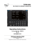
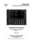
RC-9100
MULTIBAND P25 AIRBORNE TRANSCEIVER
REMOTE CONTROL
Operating Instructions
TiL Document No. 14RE509
Rev. -
MAY 2014
Technisonic Industries Limited
240 Traders Boulevard, Mississauga, Ontario L4Z 1W7
Tel: (905) 890-2113 Fax: (905) 890-5338
www.til.ca
Copyright by Technisonic Industries Limited. All rights reserved.
REVISION HISTORY
[ 14RE509 ]
REV
N/C
SECTION
- PAGE -
DESCRIPTION
Original document release
DATE
MAY 2014
Edited by
INFORMATION NOTES
ESD CAUTION
This unit contains static sensitive devices. Wear a grounded wrist strap and/or conductive gloves
when handling printed circuit boards.
FCC COMPLIANCE INFORMATION
This device complies with Part 15 of the FCC Rules. Operation is subject to the following two conditions:
(1) this device may not cause harmful interference and (2) this device must accept any interference
received, including interference that may cause undesired operation.
WARNING AND DISCLAIMER
Changes or modifications not expressly approved by Technisonic Industries could void the user’s
authority to operate the equipment.
This manual is designed to provide information about the RC-9100. Every effort has been made to make
this manual as complete and accurate as possible.
WARRANTY INFORMATION
The Model RC-9100 Remote Control Head is under warranty for one year from date of purchase. Failed
units caused by defective parts, or workmanship should be returned to:
Technisonic Industries Limited
240 Traders Boulevard
Mississauga, Ontario L4Z 1W7
Tel: (905) 890-2113
Fax: (905) 890-5338
SUMMARY OF DO-160G ENVIRONMENTAL TESTING
Summary of DO-160G Environmental Testing for Technisonic Model RC-9100 Remote Control:
Conditions
Temperature and Altitude
Category
A2, B1, C4, D1
Temperature Variation
B
Humidity
A
Operational shock and Crash Safety
A
Vibration
S, U
Magnetic Effect
Z
Power Input
B
Voltage Spike
B
Audio Frequency Susceptibility
B
Induced Signal Susceptibility
AC
Radio Frequency Susceptibility
T
Radio Frequency Emission
M
Electrostatic Discharge
A
INSTALLATION APPROVAL NOTE
Presently, no TSO standard exists for airborne FM transceivers. To make it easier for installation
agencies to provide their customers with an approved installation supported by an effective Airworthiness
Approval, Technisonic has secured Supplemental Type Certificate (STC) approval. The above referenced
DO-160G test data is also on file and available from Technisonic to support approval requirements in
airframes for which Technisonic does not possess an STC.
Approved aircraft types are listed in the attachments to the formal STC documents. These STCs are the
exclusive property of Technisonic and require the written authority of Technisonic for their use. To assist
Factory Authorized Technisonic Dealers in the certification process, we have placed copies of our
Canadian and US STCs on our web site along with a letter of authorization for their use. These
documents may be downloaded and used as support for the technical submission to FAA or Transport
Canada. Only authorized factory dealers/installers are permitted to download and make use of these
documents on behalf of their customers (end users) in support of regulatory agency approval. Please
refer to the Technisonic web site www.til.ca for the latest issue of available STCs and letter of
authorization for use.
TECHNISONIC INDUSTRIES LIMITED
www.til.ca
TABLE OF
CONTENTS
SECTION
TITLE
PAGE
SECTION 1
GENERAL DESCRIPTION
1.1
INTRODUCTION ...................................................................................................................... 1-1
1.2
DESCRIPTION ......................................................................................................................... 1-1
1.3
TECHNICAL CHARACTERISTICS .......................................................................................... 1-1
SECTION 2
OPERATING INSTRUCTIONS
2.1
GENERAL ................................................................................................................................
2.2
FRONT PANEL ........................................................................................................................
2.3
POWER ....................................................................................................................................
2.4
KNOB .......................................................................................................................................
2.5
SOFT KEYS AND HOME .........................................................................................................
2.6
BAND KEY ...............................................................................................................................
2.7
FUNC KEY ................................................................................................................................
2.8
F1 to F4 KEYS ..........................................................................................................................
2.9
MUP(4) AND MDN(7) KEYS (Memory Up and Down Keys) ....................................................
2.10
UP(5) AND DOWN(8) KEYS ....................................................................................................
2.11
BRT(6) AND DIM(9) KEYS .......................................................................................................
2.12
ESW(0) KEY (Ergo Switch Key) ...............................................................................................
2.13
TSW(*) KEY (Toggle Switch Key) ............................................................................................
2.14
DISPLAY ...................................................................................................................................
2.15
GENERAL OPERATION ..........................................................................................................
2-1
2-1
2-1
2-1
2-2
2-3
2-3
2-3
2-3
2-3
2-3
2-4
2-4
2-4
2-4
LIST OF FIGURES
FIGURE
2.1
TITLE
PAGE
Front Panel Controls – RC-9100 Remote Control..................................................................... 2-1
RC-9100 Operating Instructions
TiL 14RE509
v
TECHNISONIC INDUSTRIES LIMITED
www.til.ca
SECTION 1 - GENERAL
DESCRIPTION
1.1
INTRODUCTION
This publication provides operating and installation information on the RC-9100 remote control.
1.2
DESCRIPTION
The RC-9100 is designed to be a remote control head for the TDFM-9100 series of airborne
transceivers. It is a secondary (slave) control point and is not intended to replace the function of
the front panel of the radio.
1.3
TECHNICAL CHARACTERISTICS
Specification
Characteristic
Model Designation:
RC-9100
Physical Dimensions:
Approx. 5.75"x 3" x 1.3"
Weight:
12oz (344g)
Operating Temperature Range:
-30ºC to +60º C
Power Requirement:
Voltage:
28.0 Vdc, ± 15%
Current:
60mA minimum
150mA maximum
Communication Protocol:
RS-232
115200,N,8,1
Panel Back Lighting:
28 VDC or 5VAC
(software configurable)
RC-9100 Operating Instructions
TiL 14RE509
1-1
TECHNISONIC INDUSTRIES LIMITED
www.til.ca
This page left intentionally blank
RC-9100 Operating Instructions
TiL 14RE509
1-2
TECHNISONIC INDUSTRIES LIMITED
www.til.ca
SECTION 2 – OPERATING
INSTRUCTIONS
2.1
GENERAL
The RC-9100 is designed to be a secondary control point for the TDFM-9100 airborne
transceiver. These instructions assume a working knowledge of the TDFM-9100 transceiver.
Operation of the RC-9100 is similar to the TDFM-9100.
2.2
FRONT PANEL
Refer to the diagrams below:
FIGURE 2.1 Front Panel Controls – RC-9100 Remote Control
2.3
POWER
To switch the unit on, momentarily press the knob until the radio powers up. The unit will display
the “Technisonic” sign-on followed by the model number and current software version, along with
which RF modules are installed. The display will then show the normal display. To switch off the
transceiver at any time, press and hold the knob for 2 seconds until the display shows OFF then
release. If it is desired to have the RC unit power up with the radio master in the aircraft, an
‘always on’ mode can be set by placing a shorting jumper on J4 on the interface board inside the
unit.
2.4
KNOB
The knob is a rotary encoder, which turns endlessly. The knob also has a push button
incorporated in it so you can press the knob as well as turn it. The knob will default to control the
volume. Pressing the knob again will change its function to act as the channel selector. Another
knob press will bring you to the recall mode. In the recall mode, typing in the channel number will
bring you quickly to that channel without scrolling through many channels. Pressing the knob
RC-9100 Operating Instructions
TiL 14RE509
2-1
TECHNISONIC INDUSTRIES LIMITED
www.til.ca
again brings it back to the volume control mode. The current function of the knob is shown at the
bottom right of the display.
2.5
SOFT KEYS AND HOME
The RC unit has 3 soft keys (-) below the display. These keys assume the function shown on the
menu above them. The functions displayed depend on how the module was programmed with the
customer programming software (APX CPS)™. These menu items can be different on a channel
by channel basis. Typical menu items may include:
ZONE - Pressing this function will prompt you for a new zone number which can be entered
directly (if the keypad is in numlock mode) or scrolled using the UP(5) and DN(8)
keys.
MUTE - Selecting this function will prompt you for an on or off entry using the soft keys to
mute the tones. Tones refer to the beeps heard when pressing buttons.
PWR - Selecting PWR will allow the power output of the radio to be set to high or low.
PROG - Selecting PROG brings you to user programmable features of the radio such as
telephone numbers or scan lists. The ability for the user to program phone numbers,
scan lists, etc can be enabled or disabled by the CPS™.
VIEW - The view function is used to view lists. Lists can include scan lists, phone numbers,
call lists and or paging.
FPP - Front Panel Programming mode allows you to program at the front panel without the
customer programming software. This option is available on all standard modules.
At any time while in one of these functions, you can escape back to the normal mode by pressing
the HOME key. When programming the modules with the CPS™, it is suggested not to double up
functions. For example, programming a soft key to CHAN would be redundant since there is
already a channel function using the knob.
The six soft keys to the left of the display are used to select the active band for which the knob
and keyboard will control. If the radio is connected using the one or both of the combined inputs,
the selected band will also be selected for transmit. If you press a key on a band that is already
selected, the receive audio will be toggled off and on. This can be useful to temporarily mute
distracting traffic.
RC-9100 Operating Instructions
TiL 14RE509
2-2
TECHNISONIC INDUSTRIES LIMITED
www.til.ca
2.6
BAND KEY
This button toggles the active controls to work on either Band 1 and Band 2 as indicated by the
arrow on the left side of the display.
2.7
FUNC KEY
Pressing the FUNC key will invoke the Function menu. Pressing F1 will invoke the Configuration
Menu where the Panel Lighting voltage can be set. Use the rotary encoder to toggle between 28
VDC or 5 VAC buss lighting. Pressing Home will reboot the unit and return back to the normal
display.
2.8
F1 to F4 KEYS
Four function keys at the top of the keypad (when not programmed for quick channels as
mentioned above) provide the same actions as the three side buttons and the top button found on
the APX-7000 portable. They are as follows:
F1 – Top-side-button (purple button) on the portable.
F2 – Centre-side-button (with one dot) on the portable.
F3 – Bottom-side button (with two dots) on the portable.
F4 - Top button (orange button) on the portable.
Consult the TDFM-9100 Operating Instructions for further details.
2.9
MUP(4) AND MDN(7) KEYS (Memory Up and Down Keys)
These keys provide the same function as the rotary knob does when it is set to CHAN. These
keys can be used to scroll through the channels. A single press will step the channel by one, but
a push and hold will scroll to a desired channel number. The function of the rotary knob is
automatically set to CHAN when either of these keys is pressed.
2.10
UP(5) AND DN(8) KEYS
The keys provide the same function as the left and right arrow keys on the portable. The UP key
equates to the right arrow key and the DN is the left. These keys are used for a variety of
functions but in the normal operating mode, they are used to scroll through the soft key menus.
2.11
BRT(6) AND DIM(9) KEYS
Use these keys to dim or brighten the display. The radio powers up at full brightness for normal
use but can be dimmed for night operations.
2.12
ESW(0) KEY (Ergo Switch Key)
The ESW key provides the function of the concentric or ‘ergo’ switch on the portable. The switch
has two conditions which are represented by ‘O’ and ‘∅’. Pressing the ESW key toggles the
condition back and forth. The condition is displayed at the right hand side of the display line,
second character from the right. The ergo switch condition is saved when the unit is turned off.
There are separate conditions for each band installed. The ESW key can be programmed with
the CPS™ to a variety of functions such as low power, scan and secure or encrypted mode.
RC-9100 Operating Instructions
TiL 14RE509
2-3
TECHNISONIC INDUSTRIES LIMITED
www.til.ca
2.13
TSW(*) KEY (Toggle Switch Key)
The TSW key provides the function of the toggle switch on the portable. The switch has three
conditions which are represented by ‘A’, ‘B’ and ‘C’. Pressing the TSW key toggles the condition
A,B,C,A,B, etc. The condition is displayed at the far right hand side of the display line, last
character on the right. The toggle switch condition is saved when the unit is turned off. There are
separate conditions for each band installed. The TSW key can be programmed with the APX
CPS™ to a variety of functions such as low power, scan, zone select, or pl disabled mode.
2.14
DISPLAY
The RC-9100 has a three line, 72-character LED display. The zone number, channel name and
rotary knob function for Band 1 and Band 2 are displayed on the upper two lines. The bottom line
displays the soft key menu, the band selected, and the ESW/TSW condition. Also displayed are
letters and symbols indicating scan, direct/repeater talk around, monitor, secure, priority and call.
In addition to the character display, there are four LED indicators, 2 each on the left and right
sides. The left LEDs indicates when a signal is being received while the right LEDs indicate when
a band is transmitting. The display is always a direct copy of what is showing on the display of the
radio except when editing the brightness setting.
2.15
GENERAL OPERATION
Switch on the RC unit by momentarily pressing the knob. Select the desired band by pressing one
of the band select keys on the left of the display. Press the knob again to show CHAN on the
bottom right of the display. Rotate the knob until the desired channel or talk group is selected.
Press the knob until VOL is again shown on the display. You can adjust the volume by waiting
until a signal is received or by pressing F1 (factory programmed for monitor function) and
adjusting the rotary knob. The radio is ready to use. If the radio is installed in separate mode,
remember that the band selected by the soft keys is what menu is displayed on the screen but the
band selected by the audio panel is the band that you are transmitting and receiving on. The
numeric keypad resorts to DTMF mode while transmitting on the active (selected) band.
RC-9100 Operating Instructions
TiL 14RE509
2-4
Technisonic Industries Limited
240 Traders Blvd., Mississauga, ON Canada L4Z 1W7
Tel: (905) 890-2113 Fax: (905) 890-5338
IMPORTANT
WARRANTY
All communication equipment manufactured by Technisonic Industries Limited is
warranted to be free of defects in Material or Workmanship under normal use for a period
of one year from Date of Purchase by the end user.
Warranty will only apply to equipment installed by a factory approved and/or authorized
facility in accordance with Technisonic published installation instructions. Equipment
falling under the following is not covered by warranty:
• equipment that has been repaired or altered in any way as to affect performance,
• equipment that has been subject to improper installation,
• equipment that has been used for purposes other than intended,
• equipment that has been involved in any accident, fire, flood, immersion or subject to
any other abuse.
Expressly excluded from this warranty are changes or charges relating to the removal and
re-installation of equipment from the aircraft. Technisonic will repair or replace (at
Technisonic's discretion) any defective transceiver (or part thereof) found to be faulty
during the Warranty Period.
Faulty equipment must be returned to Technisonic (or its authorized Warranty Depot) with
transportation charges prepaid. Repaired (or replacement) equipment will be returned to
the customer with collect freight charges. If the failure of a transceiver occurs within the
first 30 days of service, Technisonic will return the repaired or replacement equipment
prepaid.
Technisonic reserves the right to make changes in design, or additions to, or
improvements in its products without obligation to install such additions and
improvements in equipment previously manufactured. This Warranty is in lieu of any and
all other warranties express or implied, including any warranty of merchantability or
fitness, and of all other obligations or liabilities on the part of Technisonic.
This Warranty shall not be transferable or assignable to any other persons, firms or
corporations.
For warranty registration please complete the on-line
Warranty Registration Form found at www.til.ca.