1
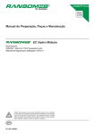
RC-7300
MULTIBAND P25 AIRBORNE TRANSCEIVER
REMOTE CONTROL
Installation and
Operating Instructions
TiL Document No. 08RE400
Rev. n/c Issue 1
NOVEMBER 2008
Technisonic Industries Limited
240 Traders Boulevard, Mississauga, Ontario L4Z 1W7
Tel: (905) 890-2113 Fax: (905) 890-5338
www.til.ca
Copyright by Technisonic Industries Limited. All rights reserved.
REVISION HISTORY
[ 08RE400 ]
REV
SECTION
- PAGE -
N/C
Issue 1
Global
1-1
3.4
DESCRIPTION
DATE
Original document release
NOV 2006
New Document template
No text information/drawings changed
Title Page layout changed
Added Revision History and Warranty page
Headers/Footers added
Baud rate changed from 115200 to 150000
Reference to IN-RC6 changed to IN-RC7
OCT 2011
i
Edited by
FM
ii
INFORMATION NOTES
ESD CAUTION
This unit contains static sensitive devices. Wear a grounded wrist strap and/or conductive
gloves when handling printed circuit boards.
FCC COMPLIANCE INFORMATION
This device complies with Part 15 of the FCC Rules. Operation is subject to the following two
conditions: (1) this device may not cause harmful interference and (2) this device must accept any
interference received, including interference that may cause undesired operation.
WARNING AND DISCLAIMER
Changes or modifications not expressly approved by Technisonic Industries could void the user’s
authority to operate the equipment.
This manual is designed to provide information about the RC-7300. Every effort has been made to
make this manual as complete and accurate as possible.
WARRANTY INFORMATION
The Model RC-7300 Remote Control Head is under warranty for one year from date of purchase.
Failed units caused by defective parts, or workmanship should be returned to:
Technisonic Industries Limited
240 Traders Boulevard
Mississauga, Ontario L4Z 1W7
Tel: (905) 890-2113
Fax: (905) 890-5338
DO-160C SUMMARY
Summary of DO-160C Environmental Qualifications for Technisonic Model RC-7300, Remote
Control Head for the Model TDFM-7300 Transceiver.
Conditions
Section
Description of Conducted Tests
Temperature and Altitude
4.0
Equipment tested to categories C4 and D1.
Vibration
8.0
Equipment is tested without shock mounts to
categories B, M and N.
Magnetic Effect
15.0
Equipment is class Z.
Power Input
16.0
Equipment tested to category B.
Voltage Spike
17.0
Equipment tested to category B.
RF Emission
21.0
Equipment tested to category Z.
TECHNISONIC INDUSTRIES LIMITED
www.til.ca
TABLE OF CONTENTS
SECTION
SECTION 1
1.1
1.2
1.3
GENERAL DESCRIPTION
1-1
1-1
1-1
OPERATING INSTRUCTIONS
GENERAL .........................................................................................................
FRONT PANEL ..................................................................................................
POWER ............................................................................................................
KNOBS ............................................................................................................
MODE KEY .......................................................................................................
F1 – F7 KEYS ...................................................................................................
FUNC KEY ........................................................................................................
DISPLAY ..........................................................................................................
GENERAL OPERATION .......................................................................................
CONFIGURATION MENU ....................................................................................
SECTION 3
3.1
3.2
3.3
3.4
3.5
3.6
3.7
PAGE
INTRODUCTION ................................................................................................
DESCRIPTION ...................................................................................................
TECHNICAL CHARACTERISTICS .........................................................................
SECTION 2
2.1
2.2
2.3
2.4
2.5
2.6
2.7
2.8
2.9
2.10
TITLE
2-1
2-1
2-1
2-1
2-2
2-2
2-2
2-2
2-2
2-2
INSTALLATION INSTRUCTIONS
GENERAL .........................................................................................................
EQUIPMENT PACKING LOG ................................................................................
RC-7300 INSTALLATION ...................................................................................
INSTALLATION KIT - CONTENTS ........................................................................
PIN LOCATIONS AND CONNECTIONS .................................................................
WIRING INSTRUCTIONS ....................................................................................
POST INSTALLATION EMI TEST .........................................................................
3-1
3-1
3-1
3-1
3-2
3-3
3-5
LIST OF FIGURES
FIGURE
TITLE
PAGE
2.1
Front Panel Controls – RC-7300 Remote Control ....................................................
2-1
3.1
3.2
Outline Drawing ................................................................................................
Wiring Connections and Notes ............................................................................
3-1
3-4
LIST OF TABLES
TABLE
3.1
3.2
TITLE
PAGE
9-Pin D-Connections (J1) ....................................................................................
9-Pin D-Connections (J4) ....................................................................................
RC-7300 Installation & Operating Instructions
3-2
3-2
TiL 08RE400 Rev n/c Issue 1
v
TECHNISONIC INDUSTRIES LIMITED
www.til.ca
RC-7300 Installation & Operating Instructions
TiL 08RE400 Rev n/c Issue 1
vi
TECHNISONIC INDUSTRIES LIMITED
www.til.ca
SECTION 1 - GENERAL DESCRIPTION
1.1
INTRODUCTION
This publication provides operating and installation information on the RC-7300 remote
control.
1.2
DESCRIPTION
The RC-7300 is designed to be a remote control head for the TDFM-7300 series of airborne
transceivers. It is a secondary (slave) control point and is not intended to replace the
function of the front panel of the radio.
1.3
TECHNICAL CHARACTERISTICS
Specification
Characteristic
Model Designation:
RC-7300
Physical Dimensions:
Approx. 5.75"x 4.5" x 1.3"
Weight:
11oz (311g)
Operating Temperature Range:
45ºC to +60º C
Power Requirement:
Voltage:
28.0 Vdc, ± 15%
Current:
85mA minimum
180mA maximum
Communication Protocol:
RS-232
150000,N,8,1
Panel Back Lighting:
28 VDC or 5VAC
(software configurable)
RC-7300 Installation & Operating Instructions
TiL 08RE400 Rev n/c Issue 1
1-1
TECHNISONIC INDUSTRIES LIMITED
www.til.ca
This page left intentionally blank
RC-7300 Installation & Operating Instructions
TiL 08RE400 Rev n/c Issue 1
1-2
TECHNISONIC INDUSTRIES LIMITED
www.til.ca
SECTION 2 – OPERATING INSTRUCTIONS
2.1
GENERAL
The RC-7300 is designed to be a secondary control point for the TDFM-7300 airborne
transceiver. These instructions assume a working knowledge of the TDFM-7300. Operation
of the RC-7300 is similar to the TDFM-7300 except for a few differences covered below.
2.2
FRONT PANEL
Refer to the diagrams below:
FIGURE 2.1 Front Panel Controls – RC-7300 Remote Control
2.3
POWER
The RC-7300 has an ON and an OFF button. Unlike the TDFM-7300 transceiver, you do not
have to hold the OFF button as it will shut off immediately.
2.4
KNOBS
The RC-7300 does not have any rotary knobs since the volume function is not required. The
volume at the remote headset should be adjusted at the remote audio panel.
RC-7300 Installation & Operating Instructions
TiL 08RE400 Rev n/c Issue 1
2-1
TECHNISONIC INDUSTRIES LIMITED
www.til.ca
2.5
MODE KEY
The MODE key has the same effect as pressing the knob on the front of the TDFM-7300.
VOL, CHAN, NUMLOCK and RECALL are the available modes.
2.6
F1-F7 KEYS
Pressing the BAND key will select the next band in sequence. A solid arrow will indicate
which band is selected. If the TDFM-7300 audio routing (see the configuration menu) is set
up in single mode, the band key also acts as the transmit select.
2.7
FUNC KEY
Pressing the function key will invoke the function menu. Functions include F1 to F4 as quick
channel keys and access to the configuration menu.
2.8
DISPLAY
The RC-7300 has a six line, 144-character LED display which always shows copy of what is
on the display of the radio except when editing the brightness setting.
2.9
GENERAL OPERATION
Switch on the RC-7300 by pressing the ON key. “TECHNISONIC” along with the firmware
version will be displayed and then the self test. If the transceiver is already on, the normal
screen will appear and the unit is ready to use. If the radio is off or is not connected, the
display will show “CONNECTING…..” until the radio is detected. If the TDFM-7300 and RC7300 are on the same power switch then the connecting message will be seen for a few
seconds as the radio takes longer to start up. The RC-7300 operates like the radio except
for the functions previously mentioned. In the case where the pilot and the remote operator
select a function at the same time, the radio panel has priority. No special settings have to
be changed on the TDFM-7300 in order for the remote to work nor does the radio care
whether the remote is present. The remote does not have to be switched on for the radio to
work.
2.10
CONFIGURATION MENU
The configuration menu can be invoked in one of two ways. Pressing the F4, ESW and TSW
keys while the unit is powered up or selecting config menu from the functions menu.
‘Configuration menu’ will be displayed at the top of the screen along with ‘Panel Lighting’.
Pressing the SEL (select) soft key will toggle the condition between 5VAC and 28VDC.
Pressing the EXIT soft key or the HOME key will save the selection and reboot the RC7300. No damage to the unit will occur if the wrong voltage is selected. Panel lighting is the
only configurable item in the RC-7300.
RC-7300 Installation & Operating Instructions
TiL 08RE400 Rev n/c Issue 1
2-2
TECHNISONIC INDUSTRIES LIMITED
www.til.ca
SECTION 3 – INSTALLATION INSTRUCTIONS
3.1
GENERAL
This section contains information and instructions for the correct installation of the RC7300 remote control.
3.2
EQUIPMENT PACKING LOG
Unpack the equipment and check for any damage that may have occurred during transit.
Save the original shipping container for returns due to damage or warranty claims. Check
that each item on the packing slip has been shipped in the container.
3.3
INSTALLATION
The RC-7300 Remote Control is designed to be Dzus mounted and should be installed in
conjunction with an IN-RC7 installation kit. See figure 3-1 for an outline drawing of the unit
with dimensions to facilitate the installation.
3.4
INSTALLATION KIT - CONTENTS
The IN-RC7 installation kit (P/N 059616-1) consists of:
1.
One 9-pin Cannon D mating connector (female) complete with crimp pins and hood.
FIGURE 3.1 Outline Drawing for Model RC-7300
RC-7300 Installation & Operating Instructions
TiL 08RE400 Rev n/c Issue 1
3-1
TECHNISONIC INDUSTRIES LIMITED
www.til.ca
3.5
INSTALLATION - PIN LOCATIONS AND CONNECTIONS
J1 (9-Pin D-Connections) - Use FEMALE Connector
Pin #
Description
Ground
Debug
Reset
+28 Volts DC
Vcc
Backlight
RX Data
TX Data
Auto ON
1
2
3
4
5
6
7
8
9
TABLE 3.1 Wire connections
J4 (9-Pin D-Connections) – Use MALE Connector
Pin #
Description
No Connection
RX Data
TX Data
No Connection
Ground
No Connection
No Connection
No Connection
No Connection
1
2
3
4
5
6
7
8
9
TABLE 3.2 Wire connections
3.6
INSTALLATION - WIRING INSTRUCTIONS
Figure 3.2 shows all required connections and recommended wire sizes for the RC-7300
Remote Control. Only J1 will be used in most installations. The second connector (J4) is
only required when the optional sat phone / position reporting equipment is installed.
3.6.1 MAIN GROUND – PIN 1, J1
Pin 1 should be connected to ground. The pin is internally connected to the chassis.
3.6.2 DEBUG - PIN 2, J1
Do not connect. This pin is used for software updates at the factory.
3.6.3 RESET - PIN 3, J1
Do not connect. This pin is also used for software updates at the factory.
RC-7300 Installation & Operating Instructions
TiL 08RE400 Rev n/c Issue 1
3-2
TECHNISONIC INDUSTRIES LIMITED
www.til.ca
3.6.4 +28 VOLTS DC - PIN 4, J1
Connect to the 28 volt DC avionics bus through a 1 amp breaker.
3.6.5 VCC - PIN 5, J1
Do not connect. This is a 5 volt output to supply the programmer for software updates at
the factory. Output current is rated at 200 mA.
3.6.6 BACKLIGHT - PIN 6, J1
Connect to the aircraft dimmer bus. Backlighting is 28 volts DC or 5 volts AC.
3.6.7 TX AND RX DATA - PINS 7 AND 8, J1
These pins are to be connected to the RS-232 pins on the TDFM-7300. TX data connects
to RX data on the radio and RX data from the remote goes to TX data on the radio.
3.6.8 AUTO ON - PIN 9, J1
Connect this pin to ground if you wish the unit to turn on with the avionics master. Leave
unconnected otherwise.
3.6.9 RX AND TX DATA - PINS 2 AND 3 (OPTIONAL), J4
Connect to the serial control port on the sat phone / position reporting equipment. Connect
RX to TX data and TX to RX data for proper operation.
3.6.10 GROUND - PIN 5 (OPTIONAL), J4
Connect to the ground on the sat phone / position reporting system serial port.
RC-7300 Installation & Operating Instructions
TiL 08RE400 Rev n/c Issue 1
3-3
TECHNISONIC INDUSTRIES LIMITED
www.til.ca
FIGURE 3.2 Wiring connections and notes for the RC-7300.
RC-7300 Installation & Operating Instructions
TiL 08RE400 Rev n/c Issue 1
3-4
TECHNISONIC INDUSTRIES LIMITED
www.til.ca
APPENDIX TO INSTALLATION INSTRUCTIONS
3.7
POST INSTALLATION EMI TEST
3.7.1
PURPOSE
The purpose of this test is to identify any interference that the RC-7300 remote control
head may cause with existing aircraft systems.
3.7.2
TEST CONDITIONS
The RC-7300 should be installed and function tested. The TDFM-7300 transceiver should
be on throughout this test.
3.7.3
METHODOLOGY
Most of the EMI tests can be accomplished on the ground.
The GPS should be operational and navigating with at least the minimum compliment of
satellites. The VHF comm should have the squelch open. VOR/DME receivers should be
selected for display. If possible, set up a DME/Transponder ramp test set and adjust the
output until the flags are out of view. The transponder and encoder should be monitored
with ramp test equipment. Set the output of the transponder test set to 3db above the
output necessary to achieve 90% reply. If possible set the ADF to a nearby navigation
station.
Switch the RC-7300 on and off as often as required.
Observe the GPS for any degradation in satellite status or availability or flags. Listen for any
noise or detected audio signals on the VHF comm(s). Listen for any noise or detected audio
signals on the VOR/LOC receiver audio; look for any moment of flags or needles on the
VOR/LOC/GS navigation display(s).
List the power plant, fuel and other electric instruments not already in the chart provided
and note any anomalies that occur due to operation of the RC-7300. Assess the results.
If the aircraft is equipped with an autopilot or a stability augmentation system, then test fly
the aircraft and verify that operation of the RC-7300 does not have adverse effects on
these systems. After checking for gross effects at a safe altitude, fly a coupled ILS
approach and look for any anomalies.
3.7.4
RESULTS
If the installed system passes all of the applicable EMI tests, then no further action is
required. If interference is observed then the interference must be assessed against the
appropriate standards of airworthiness for the system in question. A complete discussion of
all the standards of airworthiness to be applied in assessing EMI effects is beyond the scope
of this document.
RC-7300 Installation & Operating Instructions
TiL 08RE400 Rev n/c Issue 1
3-5
TECHNISONIC INDUSTRIES LIMITED
www.til.ca
3.7.5
PROCEDURE
List the power plant, fuel and other electric instruments not already included in the chart
below and note any anomalies that occur due to operation of the RC-7300. Assess the
results.
STEP
SYSTEM
1
Com 1&2
2
Transponder & Encoder
3
ADF 1 & 2
4
VG
5
Glideslope 1&2
6
VOR/LOC 1&2
7
Compass
8
Directional Gyro
9
Fuel Pressure
10
Oil Temp
11
Amps
12
Bus Voltage
PASS
RC-7300 Installation & Operating Instructions
FAIL
NOTES
TiL 08RE400 Rev n/c Issue 1
3-6
TECHNISONIC INDUSTRIES LIMITED
www.til.ca
13
Fuel %
14
Ng
15
TOT
16
Torque %
17
Enunciators
18
Digital Clock
19
Oil Pressure
20
DME 1&2
21
GPS
22
Autopilot
23
Stability Augmentation Systems
24
Coupled ILS Approach
RC-7300 Installation & Operating Instructions
TiL 08RE400 Rev n/c Issue 1
3-7
TECHNISONIC INDUSTRIES LIMITED
www.til.ca
NOTES:
RC-7300 Installation & Operating Instructions
TiL 08RE400 Rev n/c Issue 1
3-8
Technisonic Industries Limited
240 Traders Blvd., Mississauga, ON Canada L4Z 1W7
Tel: (905) 890-2113 Fax: (905) 890-5338
IMPORTANT
WARRANTY
All communication equipment manufactured by Technisonic Industries Limited is
warranted to be free of defects in Material or Workmanship under normal use for a period
of one year from Date of Purchase by the end user.
Warranty will only apply to equipment installed by a factory approved and/or authorized
facility in accordance with Technisonic published installation instructions. Equipment
falling under the following is not covered by warranty:
• equipment that has been repaired or altered in any way as to affect performance,
• equipment that has been subject to improper installation,
• equipment that has been used for purposes other than intended,
• equipment that has been involved in any accident, fire, flood, immersion or subject to
any other abuse.
Expressly excluded from this warranty are changes or charges relating to the removal and
re-installation of equipment from the aircraft. Technisonic will repair or replace (at
Technisonic's discretion) any defective transceiver (or part thereof) found to be faulty
during the Warranty Period.
Faulty equipment must be returned to Technisonic (or its authorized Warranty Depot) with
transportation charges prepaid. Repaired (or replacement) equipment will be returned to
the customer with collect freight charges. If the failure of a transceiver occurs within the
first 30 days of service, Technisonic will return the repaired or replacement equipment
prepaid.
Technisonic reserves the right to make changes in design, or additions to, or
improvements in its products without obligation to install such additions and
improvements in equipment previously manufactured. This Warranty is in lieu of any and
all other warranties express or implied, including any warranty of merchantability or
fitness, and of all other obligations or liabilities on the part of Technisonic.
This Warranty shall not be transferable or assignable to any other persons, firms or
corporations.
For warranty registration please complete the on-line
Warranty Registration Form found at www.til.ca.