1
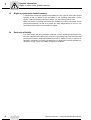
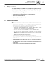
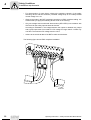
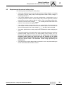
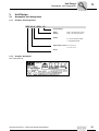
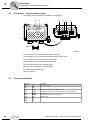
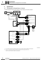
Drive Technology \ Drive Automation \ System Integration \ Services
Safety-Oriented
BST Brake Module
Edition 04/2008
16614011 / EN
Operating Instructions
SEW-EURODRIVE – Driving the world
Content
Content
1
2
General Information ............................................................................................ 5
1.1
How to use the operating instructions......................................................... 5
1.2
Structure of the safety notes ....................................................................... 5
1.3
Rights to claim under limited warranty ........................................................ 6
1.4
Exclusion of liability..................................................................................... 6
Safety Notes ........................................................................................................ 7
2.1
Preface........................................................................................................ 7
2.2
General information .................................................................................... 7
2.3
Target group ............................................................................................... 8
2.4
Designated use ........................................................................................... 8
2.5
Transport..................................................................................................... 8
2.6
Installation/assembly................................................................................... 9
2.7
Startup/operation ........................................................................................ 9
2.8
Inspection/maintenance .............................................................................. 9
2.9
Disposal ...................................................................................................... 9
3
Safety Concept .................................................................................................. 10
4
Safety Conditions.............................................................................................. 11
5
6
7
8
4.1
Installation requirements........................................................................... 11
4.2
Requirements for external safety relays ................................................... 13
4.3
Startup requirements ................................................................................ 14
4.4
Operation requirements ........................................................................... 14
Unit Design ........................................................................................................ 15
5.1
Nameplate, unit designation ..................................................................... 15
5.2
Unit design – control cabinet version ........................................................ 16
5.3
Terminal assignment................................................................................. 16
5.4
Approved unit combinations...................................................................... 17
Applications....................................................................................................... 18
6.1
Disconnection of single drives via inverter................................................ 18
6.2
Disconnection of single drives via inverter and DFS fieldbus interface .... 19
6.3
Group disconnection via inverter .............................................................. 20
Installation ......................................................................................................... 21
7.1
Mechanical Installation.............................................................................. 21
7.2
Electrical installation ................................................................................. 22
Startup/Operation.............................................................................................. 25
8.1
9
Operating status........................................................................................ 25
Inspection/Maintenance ................................................................................... 26
9.1
Inspection and maintenance intervals....................................................... 26
9.2
Checking the functionality of the brake ..................................................... 27
9.3
Service ...................................................................................................... 27
9.4
Replacing the unit .................................................................................... 27
Operating Instructions – Safety-Oriented BST Brake Module
3
Content
10
Technical Data ................................................................................................... 28
10.1 General technical data .............................................................................. 28
10.2 Dimension sheets of the BST in control cabinet design............................ 31
11
Accessories ....................................................................................................... 32
11.1 BST supply module ................................................................................... 32
12
Checklist ............................................................................................................ 33
12.1 Using the checklist .................................................................................... 33
13
Address List ...................................................................................................... 35
Index................................................................................................................... 44
4
Operating Instructions – Safety-Oriented BST Brake Module
General Information
How to use the operating instructions
1
General Information
1.1
How to use the operating instructions
1
The operating instructions are an integral part of the product and contain important information on operation and service. The operating instructions are written for all employees who assemble, install, startup, and service this product.
The operating instructions must be accessible and legible. Make sure that persons responsible for the system and its operation, as well as persons who work independently
on the unit, have read through the operating instructions carefully and understood them.
Consult SEW-EURODRIVE if you have any questions or if you require further information.
1.2
Structure of the safety notes
The safety notes in these operating instructions are structured as follows:
Symbol
SIGNAL WORD!
Nature and source of hazard.
Possible consequence(s) if disregarded.
•
Symbol
Example:
Measure(s) to avoid the hazard.
Signal word
Meaning
Consequences if disregarded
HAZARD!
Imminent hazard
Severe or fatal injuries
WARNING!
Possible hazardous situation
Severe or fatal injuries
CAUTION!
Possible hazardous situation
Minor injuries
CAUTION!
Possible damage to property
Damage to the drive system or its environment
NOTE
Useful information or tip.
Simplifies handling of the drive
system.
General hazard
Specific hazard,
e.g. electric shock
Operating Instructions – Safety-Oriented BST Brake Module
5
General Information
Rights to claim under limited warranty
1
1.3
Rights to claim under limited warranty
A requirement of fault-free operation and fulfillment of any rights to claim under limited
warranty is that you adhere to the information in the operating instructions. Consequently, read the operating instructions before you start working with the unit!
Make sure that the operating instructions are available to persons responsible for the
plant and its operation, as well as to person who work independently on the unit. You
must also ensure that the documentation is legible.
1.4
Exclusion of liability
You must comply with the information contained in these operating instructions to ensure safe operation of the BST and to achieve the specified product characteristics and
performance features. SEW-EURODRIVE assumes no liability for injury to persons or
damage to equipment or property resulting from non-observance of these operating instructions. In such cases, any liability for defects is excluded.
6
Operating Instructions – Safety-Oriented BST Brake Module
Safety Notes
Preface
2
2
Safety Notes
The following basic safety notes are intended to prevent injury to persons and damage
to property. The operator must ensure that the basic safety notes are read and observed. Make sure that persons responsible for the system and its operation, as well as
persons who work independently on the unit, have read through the operating instructions carefully and understood them. If you are unclear about any of the information in
this documentation, please contact SEW-EURODRIVE.
2.1
Preface
This document contains safety-related conditions and addendums for the operation of
BST with safe disconnection of the brake,
•
according to stop category 0 to EN 60204-1
•
Conformance with safety category 3 according to EN 954-1
•
Compliance with performance level d according to EN ISO 13849-1
•
Protection against restart in accordance with EN 1037
Also consider the supplementary safety notes in the individual sections of these operating instructions.
2.2
General information
Never install or start up damaged products. Submit a complaint to the shipping company
immediately in the event of damage.
All work related to transportation, storage, setup/mounting, connection, startup, maintenance and repair may only be carried out by qualified personnel, in strict observation of:
•
the relevant detailed operating instructions
•
the warning and safety signs
•
all other project planning documents, operating instructions and wiring diagrams
belonging to the drive
•
The specific regulations and requirements for the system
•
The national/regional regulations governing safety and the prevention of accidents
The requirements for the safety switching device and the permitted circuit variants are
specified in detail in section "Requirements for external safety switching devices" (see
page 13) and must be strictly observed.
The system/machine manufacturer must perform a system/machine-specific risk analysis. This is to take into account the BST and the mechanical brake design.
Removing covers without authorization, improper use as well as incorrect installation or
operation may result in severe injuries to persons or damage to property.
Refer to the documentation for additional information.
Operating Instructions – Safety-Oriented BST Brake Module
7
Safety Notes
Target group
2
2.3
Target group
Only qualified electricians are permitted to perform installation, startup, fault repair and
servicing (observe IEC 60364 or CENELEC HD 384 or DIN VDE 0100 and IEC 60664
or DIN VDE 0110 as well as national accident prevention regulations).
Qualified electricians in the context of these basic safety notes are persons familiar with
installation, assembly, startup and operation of the product who possess the required
qualifications.
Any activities regarding transportation, storage, operation, and disposal must be carried
out by persons who have been instructed appropriately.
2.4
Designated use
The BST safe brake module is responsible for the power supply and control of disc
brakes from SEW-EURODRIVE. The BST is intended for industrial systems and may
only be used in accordance with the information provided in SEW-EURODRIVE's technical documentation and the information given on the nameplate. For the approved combination of BST and SEW disk brake, refer to chapter "Permitted combinations" (see
page 17).
2.5
Transport
Immediately upon receipt, inspect the shipment for any damage that may have occurred
during transportation. Inform the shipping company immediately. It may be necessary to
preclude startup.
8
Operating Instructions – Safety-Oriented BST Brake Module
Safety Notes
Installation/assembly
2.6
2
Installation/assembly
Observe the notes in section "Mechanical Installation" (see page 21)!
2.7
Startup/operation
•
When the safety-related control voltage V24V safe is disconnected, the supply voltage
VZ is still present at the BST module.
•
The safety concept is only suitable for performing mechanical work on the
system/machine components.
•
All poles must be disconnected from the supply system when work is carried out on
the electrical section of the system. Dangerous voltages may still be present for up
to 10 minutes after disconnection from the power supply source.
•
You have to take into account that, in case of a fault, the application time of the connected brake is longer, thus the drive may coast.
– For the maximum application times, refer to chapter "Technical Data" of the operating instructions for the BST and the SEW disk brakes.
– Note: Should the coasting result in application-dependent hazards, you have to
provide for additional protective measures (e.g. movable covers with closure) that
cover the respective area until persons are no longer in danger.
– The additional protective covers must be designed and integrated to meet the requirements stipulated in EN ISO 12100-1 and the requirements determined for
the machine based on the risk analysis.
– After activating the stop command, access to the machine must remain blocked
until the drive has reached standstill, or the access time has to be determined to
ensure that an adequate safety distance is maintained.
2.8
Inspection/maintenance
Observe the notes in chapter "Inspection/Maintenance" (see page 26)!
2.9
Disposal
Dispose the BST in accordance with the material structure and the regulations in force
for instance as:
•
Iron
•
Copper
•
Aluminum
•
Plastic
Operating Instructions – Safety-Oriented BST Brake Module
9
Safety Concept
Disposal
3
3
Safety Concept
•
In case of danger, any potential risk resulting from a machine must be eliminated as
quickly as possible. Standstill with restart prevention is generally the safe condition
for preventing dangerous movements.
•
For drive systems, this state is achieved by activating the STO (Safe Torque Off)
function according to IEC 61800-5-2. With the BST, it is possible to use the same
safety-oriented signal that activates the STO function to provide for a safe brake
application.
•
The BST brake module is characterized by the connection option of terminal 5/6 to
an external fail-safe, prototype examined emergency stop relay. The safety switching
device disconnects the safe control voltage V24V safe when a connected control device (e.g. EMERGENCY STOP button with latching function) is activated.
•
Disconnecting the safe control voltage V24V safe means the connected brake is disconnected from the power supply. The brake cannot be released because the required power supply for creating a magnetic field is safely interrupted.
•
Instead of separating the brake control galvanically from the power supply using contactors or switches, the disconnection procedure described here prevents the power
semiconductors in the BST from being activated, thus ensuring safe disconnection.
This means that all connected brakes are de-energized although the supply voltage
is still present at the BST.
•
The requirements for the external safety switching device are clearly defined in the
following sections and must be observed.
•
Using a suitable external circuit via a safety control with
– approval to at least EN 954-1 category 3
allows for operating the BST module with safe disconnection according to
stop category 0 to EN 60204-1, fail-safe protection against restart according to
EN 1037 and fulfillment of safety category 3 to EN 954-1.
•
Using a suitable external circuit via a safety control
– approved for EN ISO 13849-1, performance level d or EN 61508, SIL 2
allows for operating the BST module with safe disconnection according to
stop category 0 to EN 60204-1, fail-safe protection against restart according to
EN 1037 and fulfillment of performance level d to EN ISO 13849-1.
•
10
The classification to category 3 according to EN 954-1, or performance level d according to EN ISO 13849-1 applies to the control not to the brake. The risk analysis
for the machine will show whether the application requires one or two brakes, for
safety reasons.
Operating Instructions – Safety-Oriented BST Brake Module
Safety Conditions
Installation requirements
4
4
Safety Conditions
The following conditions are mandatory for the installation and operation of the BST
module in applications with safe disconnection of the drive according to stop category 0
to EN 60204-1, fail-safe protection against restart to EN 1037 and conformance with
safety category 3 to EN 954-1 or performance level d to EN ISO 13849-1. The requirements are divided into the following sections:
4.1
•
Installation requirements (see page 11)
•
Requirements for external safety switching devices (see page 13)
•
Startup requirements (see page 14)
•
Operation requirements (see page 14)
Installation requirements
Observe the following notes for applications with safety-oriented disconnection of the
BST.
•
Safety-oriented control voltage V24V safe (or safety-oriented disconnection) refers to
the cable between the safety relay and the BST at terminals 5 and 6.
•
The cables must be installed according to EMC requirements:
– Outside an electrical installation space, shielded cables must be routed
permanently (fixed) and protected against external damage.
– Individual conductors can be routed inside an electrical installation space.
– The total cable length between the safety control system (e.g. safety switching
device) and the BST module is limited to a maximum length of 100 m for EMC
reasons.
– Wiring technology must comply with EN 60204-1.
•
Connect the shield to the electronics shield clamp over a large area.
•
You have to make sure that there is no transient coupling to the safety-related control
voltage V24V safe.
•
Power lines and the safety-related control cable V24V safe have to be installed in
separate cable ducts.
•
The total cable length between the BST module and the connected brake must not
exceed 200 m.
•
Do not interconnect brake cables of different brake control systems.
Operating Instructions – Safety-Oriented BST Brake Module
11
4
Safety Conditions
Installation requirements
•
For disconnection of group drives, observe the switching capacity of the safety
switching device and the maximum permitted voltage drop on the safety-related
control voltage V24V safe.
•
Observe the notes in the BST operating instructions on EMC compliant cabling. It is
essential that you apply the shielding at both ends on the housing.
•
Only use voltage sources with safe disconnection (SELV/PELV) in accordance with
VDE 0100 for the safety input at terminals 5 and 6.
According to EN 60950-1, the voltage between the outputs or between any output
and a ground part must not exceed 60 V DC voltage for longer than 0.2 s after only
one fault. The maximum DC voltage must be 120 V.
•
Adhere to the technical data of the BST module and the brake.
The following figure shows EMC compliant installation.
142874123
12
Operating Instructions – Safety-Oriented BST Brake Module
Safety Conditions
Requirements for external safety relays
4.2
4
Requirements for external safety relays
The following requirements apply to safety relays:
•
If the entire application has to meet the requirements of safety category 3 according
to EN 954-1, then the safety relay must be approved at least to safety category 3
according to EN 954-1.
•
If the entire application has to meet the requirements of performance level d
according to EN ISO 13849-1, then the safety relay must be approved at least to
performance level d according to EN ISO 13849-1 or SIL 2 according to EN 61508.
•
The safety-oriented control voltage V24V safe can be safely disconnected either at the
positive, or the positive and negative pole.
•
If the safety-oriented control voltage V24V safe is exclusively disconnected at the
positive pole and wired outside an electrical installation space, we recommend to
also route the ground of the control voltage V24V safe and lay it within the shield.
•
The values specified for the safety relays must be adhered to when designing the
circuit.
•
The switching capacity of the safety relays must correspond at least to the maximum
permitted limited output current of the safety-related control voltage V24V safe.
Observe the manufacturer's instructions for the safety relays concerning the
permitted contact loads and fusing that may be required for the safety
contacts. Unless specified otherwise, the contacts must be protected with 0.6
times the nominal value of the maximum contact rating specified by the
manufacturer.
•
The safety relays must be designed and connected in such a way that resetting the
control device itself will not lead to a restart.
Operating Instructions – Safety-Oriented BST Brake Module
13
Safety Conditions
Startup requirements
4
4.2.1
"Safety relay" sample circuit
The following figure shows the basic connection of an external safety relay (according
to the before mentioned requirements).
Observe the information in the respective manufacturer's data sheets for connection.
Approved EMERGENCY
OFF operating element
Fuses according to the
manufacturer's
specifications for the
emergency stop relay
Safety relay
with approval to at least
category 3 to EN954-1
24 V
Safety-oriented
24 V power supply of
emergency stop relay
(e.g. PNOZ...)
24 V power supply
GND
Reset button
144341643
4.3
4.4
14
Startup requirements
•
Startup must be documented and proof of the efficacy of the safety functions is
required.
•
Startup checks of the disconnecting device and the correct wiring must be basically
performed and documented for the BST module with safe disconnection of the drive
according to stop category 0 to EN 60204-1, fail-safe protection against restart to
EN 1037 and compliance with safety category 3 according to EN 954-1 or
performance level d to EN ISO 13849-1.
•
At startup, the safety-related control voltage V24V safe must be included in the
functional test.
Operation requirements
•
Operation is only allowed within the limits specified in the data sheets. This applies
to both the external safety relay as well as the BST.
•
The safety functions must be checked at regular intervals to ensure the flawless
functionality. The test intervals should be specified in accordance with the risk
analysis.
Operating Instructions – Safety-Oriented BST Brake Module
Unit Design
Nameplate, unit designation
5
Unit Design
5.1
Nameplate, unit designation
5.1.1
Example: Unit designation
5
BST 0.6 S - 400V - 00
Version/design
Brake
Voltage
Design
Rated output current
400V = AC 400 V (DC 176 V)
230V = AC 230 V (DC 96 V)
S = Control cabinet module
I = Integrated module
0.6 = DC 0.6 A
1.0 = DC 1.0 A
Series
5.1.2
Example: Nameplate
BST 0.6S-400V-00
Operating Instructions – Safety-Oriented BST Brake Module
15
Unit Design
Unit design – control cabinet version
5
5.2
Unit design – control cabinet version
Unit design of BST 0.6S-400V-00 and BST 1.0S-230V-00.
[6]
[5]
[4]
[3] [2]
13/ 14 /15 3/4 5/NC/6
[1]
1/ NC /2
[8]
[7]
142872459
[1] Terminals X1: For connecting the power supply line
[2] Terminals X2: For connecting the safety-oriented control cable
[3] Terminals X3: For connecting the control cable
[4] Terminals X4: For connecting the brake cable
[5] LED V2 for indicating the operating state
[6] LED V1 for indicating the operating state
[7] Retaining plate/shield plate
[8] PE connection
5.3
Terminal assignment
Terminal
16
Function
X1:1
X1:2
+VZ
-VZ
DC link connection
X2:5
X2:6
SVI24
SOV24
DC+24 V input "Safe stop" (safety contact)
Reference potential for DC+24 V input "Safe stop" (safety contact)
X3:3
X3:4
DBI24
DGND
Brake input
Reference potential for binary signals
X4:13
X4:14
X4:15
RD
WH
BU
Brake output
Operating Instructions – Safety-Oriented BST Brake Module
Unit Design
Approved unit combinations
5.4
5
Approved unit combinations
The following unit combinations are permitted for applications with safe disconnection
according to stop category 0 to EN 60204-1, fail-safe protection against restart to EN
1037 and compliance with safety category 3 according to EN 954-1 or performance level
d to EN ISO 13849-1.
Only approved SEW disk brakes may be connected to the BST module.
Unit designation
Part number
BST 0.6S-400V-00
1300 0772
BST 0.6I-400V-00
1270 3842
BST 1.0S-230V-00
1300 1337
BST 1.0I-230V-00
1270 5101
Operating Instructions – Safety-Oriented BST Brake Module
Approved SEW disk brakes
All brake coils with a coil voltage of AC 400 V and a coil power
≤ 95 W.
Several brake coils can be connected for redundant systems. In
this case, the total power must not exceed 95 W.
All brake coils with a coil voltage of AC 230 V and a coil power
≤ 100 W.
Several brake coils can be connected for redundant systems. In
this case, the total power must not exceed 100 W.
17
Applications
Disconnection of single drives via inverter
6
6
Applications
6.1
Disconnection of single drives via inverter
The following figure shows the block diagram for stop category 0 with brake activation.
Higher-level
control
24 V
~
Stop
=
Start
DO
DI
CPU
GND
®
MOVIDRIVE B
Emergency stop
X13:
Reset
Feedback
emergency stop
1 DIØØ
4 DIØ3
7 DCOM
/Controller inhibit
Enable/stop
Reference potential binary signals
X10:
2 DGND
3 DBØØ
Reference potential binary signals
/Brake
Safety relay
X17:
7 8
U
V
W
Reference potential binary signals
DC+24V output
Reference potential DC+24 V input
DC+24 V input
X2:
X4:
DGND
V024
S0V24
SVI24
UzUz+
PE
1
2
3
4
1)
4 5 6
M
~
Safety-oriented
brake module – BST
PE
X1:
UzN.C.
Uz+
DC link connection
DC link connection
2
2)
1
F1/F2
X2:
Reference potential DC+24 V input
DC+24 V input
S0V24
N.C.
SVI24
6
5
X3:
Reference potential binary signals
Brake input
DGND
DBI24
4
3
X4:
LED V2
LED V1
blue
white
red
BU 15
WH 14
RD 13
B
133670923
1)
2)
18
For the safe one-pole and two-pole disconnection, refer to chapter "Electrical Installation" (see page 22)
Fusing is not required if the before mentioned requirements for the supply cable are met.
Observe chapter "Electrical Installation" (see page 22).
Operating Instructions – Safety-Oriented BST Brake Module
Applications
Disconnection of single drives via inverter and DFS fieldbus interface
6.2
6
Disconnection of single drives via inverter and DFS fieldbus interface
The following figure shows the block diagram for the disconnection of single drives via inverter and DFS.
Higher-level control
24 V
=
CPU
F_CPU
GND
PROFIBUS
PROFINET
PROFIsafe
~
DI
F_DI
DO
F_DO
®
MOVIDRIVE B
X13:
1 DIØØ
7 DCOM
/Controller inhibit
Reference potential binary signals
DFS 11B/21B
X30:
X31:
1
2
3
4
5
6
F_DO_M
F_DO_P
GND
24V_LS
GND
24V_PS
1
2
3
4
DGND
V024
S0V24
SVI24
X17:
Reference potential binary signals
DC+24V output
Reference potential DC+24V input
DC+24V input
X10:
Safety-orinted
brake module – BST
Reference potential binary signals
7 8
U
V
W
X2:
/Brake
UzUz+
PE
X4:
2 DGND
3 DBØØ
4 5 6
PE
X1:
UzN.C.
Uz+
DC link connection
DC link connection
M
~
2
1
F1/F2
X2:
Reference potential DC+24V input
DC+24V input
2)
S0V24
N.C.
SVI24
6
5
X3:
Reference potential binary signals
Brake input
DGND
DBI24
4
3
X4:
LED V2
LED V1
blue
white
red
BU 15
WH 14
RD 13
B
780937611
1)
2)
For the safe one-pole and two-pole disconnection, refer to chapter "Electrical Installation" (see page 22)
Fusing is not required if the before mentioned requirements for the supply cable are met.
Observe chapter "Electrical Installation" (see page 22).
Operating Instructions – Safety-Oriented BST Brake Module
19
Applications
Group disconnection via inverter
6
6.3
Group disconnection via inverter
The following figure shows the block diagram for stop category 0 with brake activation.
Higher-level control
24 V
~
Stop
=
Start
CPU
DO
DI
GND
Reset
Feedback
emergency stop
Emergency stop
®
MOVIDRIVE B
1) Safety relay
X13:
1 DIØØ
4 DIØ3
7 DCOM
/Controller inhibit
Enable/stop
Reference potential binary signals
X10:
2 DGND
3 DBØØ
Safety-oriented
brake module – BST
Reference potential binary signals
/Brake
PE
X17:
X1:
UzN.C.
Uz+
2
S0V24
N.C.
SVI24
6
DC link connection
DC link connection
1
2
3
4
1
DGND
V024
S0V24
SVI24
Reference potential binary signals
DC+24V output
Reference potential DC+24V input
DC+24V input
X3:
Reference potential binary signals
Brake input
DGND
DBI24
7 8
U
V
W
X2:
5
X4:
DC+24V input
UzUz+
PE
X2:
Reference potential DC+24V input
4 5 6
4
3
X4:
LED V2
LED V1
blue
white
red
M
BU 15
WH 14
RD 13
~
F1/F2
2)
B
®
MOVIDRIVE B
X13:
X1:
2
X10:
1
2 DGND
3 DBØØ
X2:
Reference potential DC+24V input
DC+24V input
S0V24
N.C.
SVI24
X17:
6
1
2
3
4
5
X3:
Reference potential binary signals
Brake input
DGND
DBI24
DGND
V024
S0V24
SVI24
LED V1
BU 15
WH 14
RD 13
X4:
blue
white
red
Reference potential binary signals
DC+24V output
Reference potential DC+24V input
DC+24V input
4
3
X4:
LED V2
Reference potential binary signals
/Brake
B
7 8
U
V
W
DC link connection
Reference potential binary signals
X2:
UzN.C.
Uz+
DC link connection
/Controller inhibit
Enable/stop
1 DIØØ
4 DIØ3
7 DCOM
PE
UzUz+
PE
Safety-oriented
brake module – BST
4 5 6
F1/F2
2)
M
~
133672587
1)
2)
20
For the safe one-pole and two-pole disconnection, refer to chapter "Electrical Installation" (see page 22)
Fusing is not required if the before mentioned requirements for the supply cable are met.
Observe chapter "Electrical Installation" (see page 22).
Operating Instructions – Safety-Oriented BST Brake Module
Installation
Mechanical Installation
7
Installation
7.1
Mechanical Installation
7.1.1
DIN rail mounting
7
The BST module is mounted onto a DIN rail in the control cabinet.
137090187
•
Leave 40 mm clearance at the top, 60 mm at the bottom and 15 mm at the sides for
optimum cooling. Make sure air circulation in the clearance is not impaired by cables
or other installation equipment.
•
Ensure unobstructed cooling air supply and make sure that air heated by other units
cannot be drawn in or reused.
•
Install the units vertically only. You must not install them horizontally, tilted or upside
down.
40
Minimum clearance and mounting
position
15
60
15
137088523
Operating Instructions – Safety-Oriented BST Brake Module
21
Installation
Electrical installation
7
7.2
Electrical installation
7.2.1
Notes on electrical installation
Supply cable (terminal 1+2)
The supply cable must meet the following conditions:
•
The supply cables to the BST carry a high DC voltage (max. DC 900 V). The rated
voltage of the cable must amount to at least V0/V = 300 V / 500 V (in accordance with
DIN VDE 0298).
•
The inverter supply system must have a grounded star point (TNS/TNCS). The
operation is not permitted for IT networks or systems grounded via an outer
conductor.
•
Cable cross section: 0.75 mm2 - 2.5 mm2
•
Max. cable length: 100 m
•
All poles of the supply cable are protected with two corresponding DC fuses F1/F2
(recommended 1000 V/4 A).
NOTE
The fuses may not be required in compliance with VDE 100 part 430 and EN 60204-1
part 430 if the supply cable to the BST is protected by the input fuse located in front of
the inverter, or if the following conditions are met:
•
•
•
Control cable (terminals 3+4)
Control cable (terminals 5+6)
Brake cable (terminals 13,14,15)
22
Cable length to the BST as short as possible (max 3 m)
Cables not laid in the vicinity of inflammable substances
Risk of short circuit reduced to a minimum; use largest possible cross section
The control cable must meet the following conditions:
•
Cable cross section 0.5 - 1.5 mm2
•
Max. cable length: 100 m
The safety-oriented control cable must meet the following conditions:
•
Cable cross section 0.5 - 1.5 mm2
•
Max. cable length: 100 m
•
Cable cross section 0.75 - 2.5 mm2
•
Max. cable length: 200 m
Operating Instructions – Safety-Oriented BST Brake Module
Installation
Electrical installation
7.2.2
7
Safe single-pole disconnection
Installation space
Safety
switching device
BST
5
+U24V safe
24 V
Safety-related
voltage supply
N.C.
6
-U24V safe
133812363
Figure 1: Safe single-pole disconnection, wiring inside an electrical installation space
Installation space
Outside
installation space
Installation space
BST
Safety
switching device
5
24 V
+U24V safe
Safety-related
voltage supply
N.C.
6
-U24V safe
Figure 2: Safe single-pole disconnection, wiring outside an electrical installation space
133810699
NOTE
The safe single-pole disconnection is only permitted when short circuits in the connection cable between safety relay and BST can be ruled out (fault elimination to
EN 13849-2)
Operating Instructions – Safety-Oriented BST Brake Module
23
Installation
Electrical installation
7
7.2.3
Safe double-pole disconnection
Installation space
BST
Safety
switching device
5
+U24V safe
Safety-related
voltage supply
24 V
N.C.
6
-U24V safe
133783435
Figure 3: Safe double-pole disconnection, wiring inside an electrical installation space
Installation space
Installation space
Outside
installation space
BST
Safety
switching device
5
+U24V safe
24 V
Safety-related
voltage supply
N.C.
6
-U24V safe
Figure 4: Safe double-pole disconnection, wiring outside an electrical installation space
24
133814027
Operating Instructions – Safety-Oriented BST Brake Module
Startup/Operation
Operating status
I
8
0
8
Startup/Operation
8.1
Operating status
The brake is energized when the supply voltage VZ, the safety-oriented control voltage
V24V safe and the control voltage V24V in are present.
•
The brake is energized when the supply voltage VZ and the safety-oriented control
voltage V24V safe are present, the brake is activated via the control voltage V24V in :
V24V in = On = Brake released
V24V in = Off = Brake applied
•
If the safety-oriented control voltage V24V safe is disconnected, the brake is safely deenergized.
•
If the supply voltage VZ is disconnected, the brake is de-energized.
The brake is released via a high-speed excitation, which means that the coil section of
the brake (red – white) is supplied with the brake voltage VB for about 100 ms. Then the
complete brake coil (red – blue) is supplied with the brake voltage VB. The brake always
applies when there is a DC and AC switch-off controlled via the control voltage V24V in
or the safety-oriented control voltage V24V safe.
The response time for releasing and applying the brake results from the response time
of the BST tR ≤ 6 ms and the response or application time of the brake connected. For
the response or application times, refer to the operating instructions of the SEW disk
brakes.
8.1.1
Operating display
The LEDs indicate the operating state of the control inputs.
V24V safe
V24V in
LED V1
Off
Off
Off
Off
Brake de-energized
Off
On
Off
Off
Brake de-energized
On
Off
Lights orange
Off
Brake de-energized
On
On
Lights orange
Lights green
Brake energized when VZ is
present
Operating Instructions – Safety-Oriented BST Brake Module
LED V2
Operating status
25
Inspection/Maintenance
Inspection and maintenance intervals
9
9
Inspection/Maintenance
HAZARD!
Risk of crushing if the hoist falls.
Severe or fatal injuries.
•
•
•
•
•
•
Secure or lower hoist drives (danger of falling)
Isolate the inverter, the motor and the brake from the power supply before starting
work, safeguarding them against accidental startup.
Only use genuine spare parts in accordance with the valid parts list.
Always install a new brake controller at the same time as replacing the brake coil!
Observe the notes in the operating instructions for AC motors and brakemotors.
Only qualified personnel may perform maintenance for the brake.
HAZARD!
There may still be dangerous voltages inside the unit and at the terminal strips after the
BST has been disconnected from the power supply.
Severe or fatal injuries from electric shock.
•
Prior to maintenance or inspection work, make sure that the unit is completely deenergized.
CAUTION!
The surface temperatures on the drive can be very high during operation.
Danger of burns.
•
9.1
Let the motor cool down before you start your work.
Inspection and maintenance intervals
The required inspection/maintenance intervals must be calculated by the system manufacturer according to the specific project planning documents for individual applications, in accordance with the regionally valid standards.
26
Operating Instructions – Safety-Oriented BST Brake Module
Inspection/Maintenance
Checking the functionality of the brake
9.2
9
Checking the functionality of the brake
A functional test according to the instructions by the system manufacturer is required
after inspection/maintenance work.
9.3
Service
Please have the following information available if you require customer service assistance:
9.4
•
Nameplate data (complete)
•
Type and extent of the problem
•
Time the problem occurred and any accompanying circumstances
•
Assumed cause
Replacing the unit
Proceed as follows to replace a BST:
•
Observe the notes regarding inspection/maintenance work for the BST.
•
Compare the data on the nameplate of the BST to be replaced with the new one.
•
Remove the four connection terminals (X1 - X4).
•
Disconnect the PE and the shield clamps.
•
Push lightly on the opposite side of the connection terminals and remove the BST
from the DIN rail.
•
Install the new BST on the DIN rail. Observe chapter "Mechanical Installation".
•
Connect the PE and the shield.
•
Connect the four terminals (X1 - X4).
Operating Instructions – Safety-Oriented BST Brake Module
27
kVA
10
i
f
n
Technical Data
General technical data
P Hz
10
Technical Data
10.1
General technical data
Brake module
Part number
BST 0.6S-400V-00
(control cabinet)
BST 1.0S-230V-00
(control cabinet)
BST 0.6I-400V-00
(built-in version)
BST 1.0I-230V-00
(built-in version)
1300 0772
1300 1337
1270 3842
1270 5101
Interference resistance
according to EN 61800-3
Interference emission
with EMC-compliant
installation
according to EN 61800-3
Degree of protection
IP20
IP00
in the control cabinet on a DIN rail
MOVIPRO PHCx0Axxx unit series
Mounted on heat sink with heat sink compound
Installation
Ambient temperature
TU
Power supply
Terminals 1, 2
VZ
Supply power
Terminals 1, 2
P
Control voltage
Terminals 3, 4
V24V in
Safety-oriented control
voltage
Terminals 5, 6
V24V safe
Brake voltage
Terminals 13, 15
VB
(SEW brake type)
Rated output current
Terminals 13, 15
IN
Acceleration current
Terminals 13, 14
IB
Max. output power
Terminals 13, 15
Pab
Brake output
Terminals 13, 14, 15
28
-15°C ... +55°C at Pab
= 100%
see diagram 1
-15°C ... +45°C
-15°C ... +55°C at Pab
= 100%
see diagram 2
350 ... DC 850 V
Power consumption: 120 W, depending on brake type (holding coil)
short-term acceleration power: max. 300 W / 150 ms (accelerator coil)
Signal level according to DIN EN 61131-2 type 1 (section 5.2.3)
DC + 15V ... +30 V ( > 2 mA ) => 1 / closed contact
DC -3V ... +5 V ( < 2 mA ) => 0 / open contact
Only use voltage sources with safe disconnection (SELV/PELV) in accordance with VDE 0100
for the control input at terminals 3 and 4.
DC 24 V -15% / +20% (range: DC 20.4 V ... DC 28.8 V / < 50 mA )
according to DIN EN 61131-2 (section 5.1.1.1) DC 24 V
DC 167 V
DC 96 V
DC 167 V
DC 96 V
(AC 400 V)
(AC 230 V)
(AC 400 V)
(AC 230 V)
DC 0.6 A
DC 1.0 A
DC 0.6 A
DC 1.0 A
4 ... 8.5 times the holding current, depending on the brake type
Pab ≤ 95 W
Pab ≤ 100 W
Pab ≤ 95 W
Pab ≤ 100 W
The figures relate to the SEW standard brake coils (two-coil system)
Holding coil: Terminal 13red - 15blue
Accelerator coil: Terminal 13red - 14white
Several brake coils can be connected for redundant systems. The sum of the individual power
levels must not exceed the max. output power.
Operating Instructions – Safety-Oriented BST Brake Module
Technical Data
General technical data
Brake module
Supply cable (terminals
1+2)
BST 0.6S-400V-00
(control cabinet)
VZ
BST 1.0S-230V-00
(control cabinet)
BST 0.6I-400V-00
(built-in version)
V24V in
Cable cross section: 0.5 - 1.5 mm2
Max. cable length: 100 m
Connector: Phoenix MC 1.5/ 2-ST-3.5
Control cable
(terminals 5+6)
V24V safe
Cable cross section: 0.5 - 1.5 mm2
Max. cable length: 100 m
Connector: Phoenix MC 1.5/ 3-ST-3.5
Connector: Phoenix GIC 2.5/ 3-ST-7.62
failure per hour (MTTF
value)
P Hz
BST 1.0I-230V-00
(built-in version)
PV
Connector: Flat plug 2.8x1 + insulating housing
Max. 20 W
Performance level d according to EN ISO 13849-1
Safety category 3 according to EN 954-1
Diagnostics via an external safety relay (1oo2)
The safety relay determines the given values (MTTF, DC, CCF) for calculating the failure probability of one or several safety circuits. The BST has no effect on this.
Service life
(EN 61508)
500,000 switching cycles (brake released and brake applied) or max. 20 years
Safe status
Brake de-energized
Storage temperature
Dimensions W × H × D
Weight
10
Cable cross section 0.75 - 2.5 mm2.
Max. cable length: 200 m with min. 1.5 mm2
Brake cable
(terminals 13,14,15)
System structure
n
Connector: Flat plug 2.8x1 + insulating housing
Control cable
(terminals 3+4)
Highest possible safety
category
i
f
Rated cable voltage: min. V0 /V = 300 V / 500 V (to DIN VDE 0298)
Cable cross section: 0.75 mm2 - 2.5 mm2
Max. cable length: 100 m
Connector: Phoenix GMSTB 2.5/ 3-ST
Power loss
kVA
-20 °C...+70 °C (EN 60721-3-3, class 3K3)
134 x 70 x 135mm
121.5 X 59 x 88mm
about 730 g
about 600 g
Operating Instructions – Safety-Oriented BST Brake Module
29
10
kVA
i
f
n
Technical Data
General technical data
P Hz
10.1.1 Ambient temperature (TU) for the built-in version
Diagram 1
BST0.6I-400V-00
Pab
95W
65W
-15°C
55°C
TU
65°C
144478091
Pab = max. output power
TU = ambient temperature
Diagram 2
BST1.0I-230V-00
Pab
100W
65W
40W
-15°C
55°C
75°C
TU
65°C
144479755
Pab = max. output power
TU = ambient temperature
30
Operating Instructions – Safety-Oriented BST Brake Module
Technical Data
Dimension sheets of the BST in control cabinet design
10.2
kVA
i
f
n
10
P Hz
Dimension sheets of the BST in control cabinet design
135
99
89
135
101
70
121.5
74
133815691
Operating Instructions – Safety-Oriented BST Brake Module
31
Accessories
BST supply module
11
11
Accessories
11.1
BST supply module
Supply module for supplying the BST from a separate supply system.
Supply system
Supply system
L1
L2
L3
L1
L2
L3
1
2
3
1
2
3
Safety relay
X1:
...
...
X1:
Terminal "safe stop"
Terminal "safe stop"
X2:
Inverter
PE
UzUz+
1
2
...
...
GND
DBO
Safety-oriented
brake module – BST
PE
UzN.C.
Uz+
DC link connection
M
2 Upc in
1
X2:
DC+24 V input
4 5 6
~
X1:
DC link connection
Reference potential DC+24 V input
X2:
F1/F2
(SNR: 08295557)
without DC link connection
U
V
W
Supply module
S0V24
N.C.
SVI24
6
5
Upc in
Upc in
Upc in
X3:
Reference potential binary signals
Brake input
DGND
DBI24
U24V in
4
U24V in
3
X4:
LED V2
LED V1
BU 15
WH 14
RD 13
780890763
1)
32
Fusing is not required if the before mentioned requirements for the supply cable are met.
Observe chapter "Electrical Installation" (see page 22).
Operating Instructions – Safety-Oriented BST Brake Module
Checklist
Using the checklist
I
12
0
12
Checklist
12.1
Using the checklist
The checklist helps you perform project planning, installation and startup for the connection variants described above.
NOTE
•
Correct use of the checklists and the connection-specific addendums can
meet the requirement for documented startup and proof of the efficacy of the
safety functions.
Additional requirements may arise depending on the system.
The checklist is not exhaustive.
•
•
No.
Requirement
1
General requirements
1.1
Has a risk analysis according to EN 1050/ EN ISO 14121-1 been
performed that proved:
• that safety category 3 can be realized?
• that the performance level d can be realized?
• which stop category (0 or 1) must be realized to EN 60204-1?
2.
General demands on units and installation
2.1
Do all the DC 24 V voltage sources/power supply units used comply
with EN 60950-1?
2.2
Have the notes regarding EMC-compliant wiring been observed?
2.3
Was the safety-oriented control voltage V24V safe installed as follows?
• EMC-compliant cabling (i.e. routed separately from motor cables
and other cables carrying switched-mode signals)
• Either in cable ducts or conduits
• Or using shielded cables
• Using suitable terminal strips for the distribution.
3.
Requirements for external safety relays
3.1
Has the safety switching device in use at least approval according to
safety category 3 to EN 954-1, EN 61508 SIL 2, or performance
level d to EN ISO 13849-1?
3.2
Have the values specified for the stop relay been strictly observed in
the circuit design?
3.3
Has the switching capacity of the emergency stop relay been taken
into account and corresponding fusing been carried out?
Operating Instructions – Safety-Oriented BST Brake Module
Met
Yes
No
Comment
33
12
I
Checklist
Using the checklist
0
34
Met
No.
Requirement
4.
Startup requirements
4.1
Have you checked the connection for the signals displayed in the
connection variants?
4.2
Has a commissioning test of the disconnecting device been carried
out and the correct wiring been checked and recorded in writing?
4.3
Has the operating display been included in the functional test during
startup?
5.
Operation requirements
5.1
Can the units/components in the safety area be operated within the
limits specified in the data sheets?
5.2
Is the safety function checked at regular intervals?
Yes
No
Comment
Operating Instructions – Safety-Oriented BST Brake Module
Address List
Using the checklist
13
13
Address List
Germany
Headquarters
Production
Sales
Bruchsal
SEW-EURODRIVE GmbH & Co KG
Ernst-Blickle-Straße 42
D-76646 Bruchsal
P.O. Box
Postfach 3023 • D-76642 Bruchsal
Tel. +49 7251 75-0
Fax +49 7251 75-1970
http://www.sew-eurodrive.de
[email protected]
Service Competence Center
Central
SEW-EURODRIVE GmbH & Co KG
Ernst-Blickle-Straße 1
D-76676 Graben-Neudorf
Tel. +49 7251 75-1710
Fax +49 7251 75-1711
[email protected]
North
SEW-EURODRIVE GmbH & Co KG
Alte Ricklinger Straße 40-42
D-30823 Garbsen (near Hannover)
Tel. +49 5137 8798-30
Fax +49 5137 8798-55
[email protected]
East
SEW-EURODRIVE GmbH & Co KG
Dänkritzer Weg 1
D-08393 Meerane (near Zwickau)
Tel. +49 3764 7606-0
Fax +49 3764 7606-30
[email protected]
South
SEW-EURODRIVE GmbH & Co KG
Domagkstraße 5
D-85551 Kirchheim (near München)
Tel. +49 89 909552-10
Fax +49 89 909552-50
[email protected]
West
SEW-EURODRIVE GmbH & Co KG
Siemensstraße 1
D-40764 Langenfeld (near Düsseldorf)
Tel. +49 2173 8507-30
Fax +49 2173 8507-55
[email protected]
Electronics
SEW-EURODRIVE GmbH & Co KG
Ernst-Blickle-Straße 42
D-76646 Bruchsal
Tel. +49 7251 75-1780
Fax +49 7251 75-1769
[email protected]
Drive Service Hotline / 24 Hour Service
+49 180 5 SEWHELP
+49 180 5 7394357
Additional addresses for service in Germany provided on request!
France
Production
Sales
Service
Haguenau
SEW-USOCOME
48-54, route de Soufflenheim
B. P. 20185
F-67506 Haguenau Cedex
Tel. +33 3 88 73 67 00
Fax +33 3 88 73 66 00
http://www.usocome.com
[email protected]
Production
Forbach
SEW-EUROCOME
Zone Industrielle
Technopôle Forbach Sud
B. P. 30269
F-57604 Forbach Cedex
Tel. +33 3 87 29 38 00
Assembly
Sales
Service
Bordeaux
SEW-USOCOME
Parc d'activités de Magellan
62, avenue de Magellan - B. P. 182
F-33607 Pessac Cedex
Tel. +33 5 57 26 39 00
Fax +33 5 57 26 39 09
Lyon
SEW-USOCOME
Parc d'Affaires Roosevelt
Rue Jacques Tati
F-69120 Vaulx en Velin
Tel. +33 4 72 15 37 00
Fax +33 4 72 15 37 15
Paris
SEW-USOCOME
Zone industrielle
2, rue Denis Papin
F-77390 Verneuil I'Etang
Tel. +33 1 64 42 40 80
Fax +33 1 64 42 40 88
Additional addresses for service in France provided on request!
Operating Instructions – Safety-Oriented BST Brake Module
35
Address List
Using the checklist
13
Algeria
Sales
Alger
Réducom
16, rue des Frères Zaghnoun
Bellevue El-Harrach
16200 Alger
Tel. +213 21 8222-84
Fax +213 21 8222-84
[email protected]
Buenos Aires
SEW EURODRIVE ARGENTINA S.A.
Centro Industrial Garin, Lote 35
Ruta Panamericana Km 37,5
1619 Garin
Tel. +54 3327 4572-84
Fax +54 3327 4572-21
[email protected]
http://www.sew-eurodrive.com.ar
Melbourne
SEW-EURODRIVE PTY. LTD.
27 Beverage Drive
Tullamarine, Victoria 3043
Tel. +61 3 9933-1000
Fax +61 3 9933-1003
http://www.sew-eurodrive.com.au
[email protected]
Sydney
SEW-EURODRIVE PTY. LTD.
9, Sleigh Place, Wetherill Park
New South Wales, 2164
Tel. +61 2 9725-9900
Fax +61 2 9725-9905
[email protected]
Townsville
SEW-EURODRIVE PTY. LTD.
12 Leyland Street
Garbutt, QLD 4814
Tel. +61 7 4779 4333
Fax +61 7 4779 5333
[email protected]
Wien
SEW-EURODRIVE Ges.m.b.H.
Richard-Strauss-Strasse 24
A-1230 Wien
Tel. +43 1 617 55 00-0
Fax +43 1 617 55 00-30
http://sew-eurodrive.at
[email protected]
Minsk
SEW-EURODRIVE BY
RybalkoStr. 26
BY-220033 Minsk
Tel.+375 (17) 298 38 50
Fax +375 (17) 29838 50
[email protected]
Assembly
Sales
Service
Brüssel
SEW Caron-Vector S.A.
Avenue Eiffel 5
B-1300 Wavre
Tel. +32 10 231-311
Fax +32 10 231-336
http://www.sew-eurodrive.be
[email protected]
Service Competence Center
Industrial Gears
SEW Caron-Vector S.A.
Rue de Parc Industriel, 31
BE-6900 Marche-en-Famenne
Tel. +32 84 219-878
Fax +32 84 219-879
http://www.sew-eurodrive.be
[email protected]
Sao Paulo
SEW-EURODRIVE Brasil Ltda.
Avenida Amâncio Gaiolli, 152 – Rodovia Presidente Dutra Km 208
Guarulhos – 07251-250 - SP
SAT – SEW ATENDE – 0800 7700496
Tel. +55 11 6489-9133
Fax +55 11 6480-3328
http://www.sew.com.br
[email protected]
Argentina
Assembly
Sales
Service
Australia
Assembly
Sales
Service
Austria
Assembly
Sales
Service
Belarus
Sales
Belgium
Brazil
Production
Sales
Service
Additional addresses for service in Brazil provided on request!
Bulgaria
Sales
36
Sofia
BEVER-DRIVE GmbH
Bogdanovetz Str.1
BG-1606 Sofia
Tel. +359 2 9151160
Fax +359 2 9151166
[email protected]
Operating Instructions – Safety-Oriented BST Brake Module
Address List
Using the checklist
13
Cameroon
Sales
Douala
Electro-Services
Rue Drouot Akwa
B.P. 2024
Douala
Tel. +237 33 431137
Fax +237 33 431137
Toronto
SEW-EURODRIVE CO. OF CANADA LTD.
210 Walker Drive
Bramalea, Ontario L6T3W1
Tel. +1 905 791-1553
Fax +1 905 791-2999
http://www.sew-eurodrive.ca
[email protected]
Vancouver
SEW-EURODRIVE CO. OF CANADA LTD.
7188 Honeyman Street
Delta. B.C. V4G 1 E2
Tel. +1 604 946-5535
Fax +1 604 946-2513
[email protected]
Montreal
SEW-EURODRIVE CO. OF CANADA LTD.
2555 Rue Leger
LaSalle, Quebec H8N 2V9
Tel. +1 514 367-1124
Fax +1 514 367-3677
[email protected]
Canada
Assembly
Sales
Service
Additional addresses for service in Canada provided on request!
Chile
Santiago de
Chile
SEW-EURODRIVE CHILE LTDA.
Las Encinas 1295
Parque Industrial Valle Grande
LAMPA
RCH-Santiago de Chile
P.O. Box
Casilla 23 Correo Quilicura - Santiago - Chile
Tel. +56 2 75770-00
Fax +56 2 75770-01
http://www.sew-eurodrive.cl
[email protected]
Production
Assembly
Sales
Service
Tianjin
SEW-EURODRIVE (Tianjin) Co., Ltd.
No. 46, 7th Avenue, TEDA
Tianjin 300457
Tel. +86 22 25322612
Fax +86 22 25322611
[email protected]
http://www.sew-eurodrive.cn
Assembly
Sales
Service
Suzhou
SEW-EURODRIVE (Suzhou) Co., Ltd.
333, Suhong Middle Road
Suzhou Industrial Park
Jiangsu Province, 215021
Tel. +86 512 62581781
Fax +86 512 62581783
[email protected]
Guangzhou
SEW-EURODRIVE (Guangzhou) Co., Ltd.
No. 9, JunDa Road
East Section of GETDD
Guangzhou 510530
Tel. +86 20 82267890
Fax +86 20 82267891
[email protected]
Shenyang
SEW-EURODRIVE (Shenyang) Co., Ltd.
10A-2, 6th Road
Shenyang Economic Technological Development Area
Shenyang, 110141
Tel. +86 24 25382538
Fax +86 24 25382580
[email protected]
Assembly
Sales
Service
China
Additional addresses for service in China provided on request!
Colombia
Assembly
Sales
Service
Bogotá
SEW-EURODRIVE COLOMBIA LTDA.
Calle 22 No. 132-60
Bodega 6, Manzana B
Santafé de Bogotá
Tel. +57 1 54750-50
Fax +57 1 54750-44
http://www.sew-eurodrive.com.co
[email protected]
Zagreb
KOMPEKS d. o. o.
PIT Erdödy 4 II
HR 10 000 Zagreb
Tel. +385 1 4613-158
Fax +385 1 4613-158
[email protected]
Croatia
Sales
Service
Operating Instructions – Safety-Oriented BST Brake Module
37
Address List
Using the checklist
13
Czech Republic
Sales
Praha
SEW-EURODRIVE CZ S.R.O.
Business Centrum Praha
Lužná 591
CZ-16000 Praha 6 - Vokovice
Tel. +420 220121234
Fax +420 220121237
http://www.sew-eurodrive.cz
[email protected]
Kopenhagen
SEW-EURODRIVEA/S
Geminivej 28-30
DK-2670 Greve
Tel. +45 43 9585-00
Fax +45 43 9585-09
http://www.sew-eurodrive.dk
[email protected]
Cairo
Copam Egypt
for Engineering & Agencies
33 EI Hegaz ST, Heliopolis, Cairo
Tel. +20 2 22566-299 + 1 23143088
Fax +20 2 22594-757
http://www.copam-egypt.com/
[email protected]
Tallin
ALAS-KUUL AS
Reti tee 4
EE-75301 Peetri küla, Rae vald, Harjumaa
Tel. +372 6593230
Fax +372 6593231
[email protected]
Assembly
Sales
Service
Lahti
SEW-EURODRIVE OY
Vesimäentie 4
FIN-15860 Hollola 2
Tel. +358 201 589-300
Fax +358 3 780-6211
[email protected]
http://www.sew-eurodrive.fi
Production
Assembly
Service
Karkkila
SEW Industrial Gears OY
Valurinkatu 6
FIN-03600 Karkkila
Tel. +358 201 589-300
Fax +358 201 589-310
[email protected]
http://www.sew-eurodrive.fi
Libreville
Electro-Services
B.P. 1889
Libreville
Tel. +241 7340-11
Fax +241 7340-12
Normanton
SEW-EURODRIVE Ltd.
Beckbridge Industrial Estate
P.O. Box No.1
GB-Normanton, West- Yorkshire WF6 1QR
Tel. +44 1924 893-855
Fax +44 1924 893-702
http://www.sew-eurodrive.co.uk
[email protected]
Athen
Christ. Boznos & Son S.A.
12, Mavromichali Street
P.O. Box 80136, GR-18545 Piraeus
Tel. +30 2 1042 251-34
Fax +30 2 1042 251-59
http://www.boznos.gr
[email protected]
Hong Kong
SEW-EURODRIVE LTD.
Unit No. 801-806, 8th Floor
Hong Leong Industrial Complex
No. 4, Wang Kwong Road
Kowloon, Hong Kong
Tel. +852 2 7960477 + 79604654
Fax +852 2 7959129
[email protected]
Denmark
Assembly
Sales
Service
Egypt
Sales
Service
Estonia
Sales
Finland
Gabon
Sales
Great Britain
Assembly
Sales
Service
Greece
Sales
Service
Hong Kong
Assembly
Sales
Service
38
Operating Instructions – Safety-Oriented BST Brake Module
Address List
Using the checklist
13
Hungary
Sales
Service
Budapest
SEW-EURODRIVE Kft.
H-1037 Budapest
Kunigunda u. 18
Tel. +36 1 437 06-58
Fax +36 1 437 06-50
[email protected]
Vadodara
SEW-EURODRIVE India Private Limited
Plot No. 4, GIDC
POR Ramangamdi • Vadodara - 391 243
Gujarat
Tel. +91 265 2831086
Fax +91 265 2831087
http://www.seweurodriveindia.com
[email protected]
[email protected]
Dublin
Alperton Engineering Ltd.
48 Moyle Road
Dublin Industrial Estate
Glasnevin, Dublin 11
Tel. +353 1 830-6277
Fax +353 1 830-6458
[email protected]
http://www.alperton.ie
Tel-Aviv
Liraz Handasa Ltd.
Ahofer Str 34B / 228
58858 Holon
Tel. +972 3 5599511
Fax +972 3 5599512
http://www.liraz-handasa.co.il
[email protected]
Milano
SEW-EURODRIVE di R. Blickle & Co.s.a.s.
Via Bernini,14
I-20020 Solaro (Milano)
Tel. +39 02 96 9801
Fax +39 02 96 799781
http://www.sew-eurodrive.it
[email protected]
Abidjan
SICA
Ste industrielle et commerciale pour l'Afrique
165, Bld de Marseille
B.P. 2323, Abidjan 08
Tel. +225 2579-44
Fax +225 2584-36
Iwata
SEW-EURODRIVE JAPAN CO., LTD
250-1, Shimoman-no,
Iwata
Shizuoka 438-0818
Tel. +81 538 373811
Fax +81 538 373814
http://www.sew-eurodrive.co.jp
[email protected]
Ansan-City
SEW-EURODRIVE KOREA CO., LTD.
B 601-4, Banweol Industrial Estate
1048-4, Shingil-Dong
Ansan 425-120
Tel. +82 31 492-8051
Fax +82 31 492-8056
http://www.sew-korea.co.kr
[email protected]
Busan
SEW-EURODRIVE KOREA Co., Ltd.
No. 1720 - 11, Songjeong - dong
Gangseo-ku
Busan 618-270
Tel. +82 51 832-0204
Fax +82 51 832-0230
[email protected]
Riga
SIA Alas-Kuul
Katlakalna 11C
LV-1073 Riga
Tel. +371 7139253
Fax +371 7139386
http://www.alas-kuul.com
[email protected]
India
Assembly
Sales
Service
Ireland
Sales
Service
Israel
Sales
Italy
Assembly
Sales
Service
Ivory Coast
Sales
Japan
Assembly
Sales
Service
Korea
Assembly
Sales
Service
Latvia
Sales
Operating Instructions – Safety-Oriented BST Brake Module
39
Address List
Using the checklist
13
Lebanon
Sales
Beirut
Gabriel Acar & Fils sarl
B. P. 80484
Bourj Hammoud, Beirut
Tel. +961 1 4947-86
+961 1 4982-72
+961 3 2745-39
Fax +961 1 4949-71
[email protected]
Alytus
UAB Irseva
Naujoji 19
LT-62175 Alytus
Tel. +370 315 79204
Fax +370 315 56175
[email protected]
http://www.sew-eurodrive.lt
Brüssel
CARON-VECTOR S.A.
Avenue Eiffel 5
B-1300 Wavre
Tel. +32 10 231-311
Fax +32 10 231-336
http://www.sew-eurodrive.lu
[email protected]
Johore
SEW-EURODRIVE SDN BHD
No. 95, Jalan Seroja 39, Taman Johor Jaya
81000 Johor Bahru, Johor
West Malaysia
Tel. +60 7 3549409
Fax +60 7 3541404
[email protected]
Queretaro
SEW-EURODRIVE MEXIKO SA DE CV
SEM-981118-M93
Tequisquiapan No. 102
Parque Industrial Queretaro
C.P. 76220
Queretaro, Mexico
Tel. +52 442 1030-300
Fax +52 442 1030-301
http://www.sew-eurodrive.com.mx
[email protected]
Casablanca
Afit
5, rue Emir Abdelkader
MA 20300 Casablanca
Tel. +212 22618372
Fax +212 22618351
[email protected]
Rotterdam
VECTOR Aandrijftechniek B.V.
Industrieweg 175
NL-3044 AS Rotterdam
Postbus 10085
NL-3004 AB Rotterdam
Tel. +31 10 4463-700
Fax +31 10 4155-552
http://www.vector.nu
[email protected]
Auckland
SEW-EURODRIVE NEW ZEALAND LTD.
P.O. Box 58-428
82 Greenmount drive
East Tamaki Auckland
Tel. +64 9 2745627
Fax +64 9 2740165
http://www.sew-eurodrive.co.nz
[email protected]
Christchurch
SEW-EURODRIVE NEW ZEALAND LTD.
10 Settlers Crescent, Ferrymead
Christchurch
Tel. +64 3 384-6251
Fax +64 3 384-6455
[email protected]
Moss
SEW-EURODRIVE A/S
Solgaard skog 71
N-1599 Moss
Tel. +47 69 24 10 20
Fax +47 69 24 10 40
http://www.sew-eurodrive.no
[email protected]
Lithuania
Sales
Luxembourg
Assembly
Sales
Service
Malaysia
Assembly
Sales
Service
Mexico
Assembly
Sales
Service
Morocco
Sales
Netherlands
Assembly
Sales
Service
New Zealand
Assembly
Sales
Service
Norway
Assembly
Sales
Service
40
Operating Instructions – Safety-Oriented BST Brake Module
Address List
Using the checklist
13
Peru
Assembly
Sales
Service
Lima
SEW DEL PERU MOTORES REDUCTORES
S.A.C.
Los Calderos, 120-124
Urbanizacion Industrial Vulcano, ATE, Lima
Tel. +51 1 3495280
Fax +51 1 3493002
http://www.sew-eurodrive.com.pe
[email protected]
Lodz
SEW-EURODRIVE Polska Sp.z.o.o.
ul. Techniczna 5
PL-92-518 Łódź
Tel. +48 42 67710-90
Fax +48 42 67710-99
http://www.sew-eurodrive.pl
[email protected]
24 Hour Service
Tel. +48 602 739 739
(+48 602 SEW SEW)
[email protected]
Coimbra
SEW-EURODRIVE, LDA.
Apartado 15
P-3050-901 Mealhada
Tel. +351 231 20 9670
Fax +351 231 20 3685
http://www.sew-eurodrive.pt
[email protected]
Bucureşti
Sialco Trading SRL
str. Madrid nr.4
011785 Bucuresti
Tel. +40 21 230-1328
Fax +40 21 230-7170
[email protected]
St. Petersburg
ZAO SEW-EURODRIVE
P.O. Box 36
195220 St. Petersburg Russia
Tel. +7 812 3332522 +7 812 5357142
Fax +7 812 3332523
http://www.sew-eurodrive.ru
[email protected]
Dakar
SENEMECA
Mécanique Générale
Km 8, Route de Rufisque
B.P. 3251, Dakar
Tel. +221 338 494 770
Fax +221 338 494 771
[email protected]
Beograd
DIPAR d.o.o.
Ustanicka 128a
PC Košum, IV floor
SCG-11000 Beograd
Tel. +381 11 347 3244 / +381 11 288
0393
Fax +381 11 347 1337
[email protected]
Singapore
SEW-EURODRIVE PTE. LTD.
No 9, Tuas Drive 2
Jurong Industrial Estate
Singapore 638644
Tel. +65 68621701
Fax +65 68612827
http://www.sew-eurodrive.com.sg
[email protected]
Bratislava
SEW-Eurodrive SK s.r.o.
Rybničná 40
SK-83554 Bratislava
Tel. +421 2 49595201
Fax +421 2 49595200
[email protected]
http://www.sew-eurodrive.sk
Žilina
SEW-Eurodrive SK s.r.o.
ul. Vojtecha Spanyola 33
SK-010 01 Žilina
Tel. +421 41 700 2513
Fax +421 41 700 2514
[email protected]
Poland
Assembly
Sales
Service
Portugal
Assembly
Sales
Service
Romania
Sales
Service
Russia
Assembly
Sales
Service
Senegal
Sales
Serbia
Sales
Singapore
Assembly
Sales
Service
Slovakia
Sales
Operating Instructions – Safety-Oriented BST Brake Module
41
Address List
Using the checklist
13
Slovakia
Banská Bystrica
SEW-Eurodrive SK s.r.o.
Rudlovská cesta 85
SK-97411 Banská Bystrica
Tel. +421 48 414 6564
Fax +421 48 414 6566
[email protected]
Celje
Pakman - Pogonska Tehnika d.o.o.
UI. XIV. divizije 14
SLO - 3000 Celje
Tel. +386 3 490 83-20
Fax +386 3 490 83-21
[email protected]
Johannesburg
SEW-EURODRIVE (PROPRIETARY) LIMITED
Eurodrive House
Cnr. Adcock Ingram and Aerodrome Roads
Aeroton Ext. 2
Johannesburg 2013
P.O.Box 90004
Bertsham 2013
Tel. +27 11 248-7000
Fax +27 11 494-3104
http://www.sew.co.za
[email protected]
Capetown
SEW-EURODRIVE (PROPRIETARY) LIMITED
Rainbow Park
Cnr. Racecourse & Omuramba Road
Montague Gardens
Cape Town
P.O.Box 36556
Chempet 7442
Cape Town
Tel. +27 21 552-9820
Fax +27 21 552-9830
Telex 576 062
[email protected]
Durban
SEW-EURODRIVE (PROPRIETARY) LIMITED
2 Monaceo Place
Pinetown
Durban
P.O. Box 10433, Ashwood 3605
Tel. +27 31 700-3451
Fax +27 31 700-3847
[email protected]
Bilbao
SEW-EURODRIVE ESPAÑA, S.L.
Parque Tecnológico, Edificio, 302
E-48170 Zamudio (Vizcaya)
Tel. +34 94 43184-70
Fax +34 94 43184-71
http://www.sew-eurodrive.es
[email protected]
Jönköping
SEW-EURODRIVE AB
Gnejsvägen 6-8
S-55303 Jönköping
Box 3100 S-55003 Jönköping
Tel. +46 36 3442-00
Fax +46 36 3442-80
http://www.sew-eurodrive.se
[email protected]
Basel
Alfred lmhof A.G.
Jurastrasse 10
CH-4142 Münchenstein bei Basel
Tel. +41 61 417 1717
Fax +41 61 417 1700
http://www.imhof-sew.ch
[email protected]
Chonburi
SEW-EURODRIVE (Thailand) Ltd.
700/456, Moo.7, Donhuaroh
Muang
Chonburi 20000
Tel. +66 38 454281
Fax +66 38 454288
[email protected]
Tunis
T. M.S. Technic Marketing Service
5, Rue El Houdaibiah
1000 Tunis
Tel. +216 71 4340-64 + 71 4320-29
Fax +216 71 4329-76
[email protected]
Slovenia
Sales
Service
South Africa
Assembly
Sales
Service
Spain
Assembly
Sales
Service
Sweden
Assembly
Sales
Service
Switzerland
Assembly
Sales
Service
Thailand
Assembly
Sales
Service
Tunisia
Sales
42
Operating Instructions – Safety-Oriented BST Brake Module
Address List
Using the checklist
13
Turkey
Assembly
Sales
Service
Istanbul
SEW-EURODRIVE
Hareket Sistemleri San. ve Tic. Ltd. Sti.
Bagdat Cad. Koruma Cikmazi No. 3
TR-34846 Maltepe ISTANBUL
Tel. +90 216 4419164, 3838014,
3738015
Fax +90 216 3055867
http://www.sew-eurodrive.com.tr
[email protected]
Dnepropetrovsk
SEW-EURODRIVE
Str. Rabochaja 23-B, Office 409
49008 Dnepropetrovsk
Tel. +380 56 370 3211
Fax +380 56 372 2078
http://www.sew-eurodrive.ua
[email protected]
Production
Assembly
Sales
Service
Greenville
SEW-EURODRIVE INC.
1295 Old Spartanburg Highway
P.O. Box 518
Lyman, S.C. 29365
Tel. +1 864 439-7537
Fax Sales +1 864 439-7830
Fax Manuf. +1 864 439-9948
Fax Ass. +1 864 439-0566
Telex 805 550
http://www.seweurodrive.com
[email protected]
Assembly
Sales
Service
San Francisco
SEW-EURODRIVE INC.
30599 San Antonio St.
Hayward, California 94544-7101
Tel. +1 510 487-3560
Fax +1 510 487-6433
[email protected]
Philadelphia/PA
SEW-EURODRIVE INC.
Pureland Ind. Complex
2107 High Hill Road, P.O. Box 481
Bridgeport, New Jersey 08014
Tel. +1 856 467-2277
Fax +1 856 845-3179
[email protected]
Dayton
SEW-EURODRIVE INC.
2001 West Main Street
Troy, Ohio 45373
Tel. +1 937 335-0036
Fax +1 937 440-3799
[email protected]
Dallas
SEW-EURODRIVE INC.
3950 Platinum Way
Dallas, Texas 75237
Tel. +1 214 330-4824
Fax +1 214 330-4724
[email protected]
Ukraine
Sales
Service
USA
Additional addresses for service in the USA provided on request!
Venezuela
Assembly
Sales
Service
Valencia
SEW-EURODRIVE Venezuela S.A.
Av. Norte Sur No. 3, Galpon 84-319
Zona Industrial Municipal Norte
Valencia, Estado Carabobo
Operating Instructions – Safety-Oriented BST Brake Module
Tel. +58 241 832-9804
Fax +58 241 838-6275
http://www.sew-eurodrive.com.ve
[email protected]
[email protected]
43
Index
Index
A
R
Accessories............................................................32
Applications
Disconnection of single drives via inverter.........18
Disconnection of single drives via inverter
and DFS fieldbus interface...............................19
Group disconnection via inverter .......................20
Requirements
External safety relays ........................................13
Installation..........................................................11
Operation ...........................................................14
Startup ...............................................................14
Rights to claim under limited warranty.....................6
C
S
Checklist ................................................................33
Use.....................................................................33
Safe disconnection
Double-pole .......................................................24
Single-pole.........................................................23
Safe double-pole disconnection.............................24
Safe single-pole disconnection ..............................23
Safety concept .......................................................10
Safety conditions ...................................................11
Safety notes.............................................................7
Safety relay
Sample circuit ....................................................14
Safety relays, external
Requirements ....................................................13
Startup ................................................................... 25
Requirements ....................................................14
Structure of the safety notes....................................5
Supply module .......................................................32
D
Designated use ........................................................8
Dimension sheets ..................................................31
Disposal ...................................................................9
E
Electrical installation...............................................22
Exclusion of liability ..................................................6
External safety relays
Requirements.....................................................13
I
Inspection...............................................................26
Inspection intervals ................................................26
Installation
Electrical ............................................................22
Mechanical.........................................................21
Requirements.....................................................11
M
Maintenance ..........................................................26
Maintenance intervals ............................................26
Mechanical installation ...........................................21
T
Technical data .......................................................28
Terminal assignment .............................................16
Transport .................................................................8
U
Unit combinations ..................................................17
Unit design.............................................................16
Unit designation .....................................................15
N
Nameplate..............................................................15
O
Operation ...............................................................25
Requirements.....................................................14
44
Operating Instructions – Safety-Oriented BST Brake Module
SEW-EURODRIVE – Driving the world
Drive Technology \ Drive Automation \ System Integration \ Services
How we’re driving the world
With people who
think fast and
develop the
future with you.
With a worldwide
service network that is
always close at hand.
With comprehensive
knowledge in virtually
every branch of
industry today.
With drives and controls
that automatically
improve your productivity.
With uncompromising
quality that reduces the
cost and complexity of
daily operations.
SEW-EURODRIVE
Driving the world
With a global presence
that offers responsive
and reliable solutions.
Anywhere.
With innovative
technology that solves
tomorrow’s problems
today.
With online information
and software updates,
via the Internet, available
around the clock.
SEW-EURODRIVE GmbH & Co KG
P.O. Box 3023 · D-76642 Bruchsal / Germany
Phone +49 7251 75-0 · Fax +49 7251 75-1970
[email protected]
www.sew-eurodrive.com