1
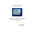
Operating Instructions Vision 5L Digital Holter Recorder Document Number: 010-1646-00 Revision: H Bothell, Washington 98021-8969 (608)-764-1919 Vision 5L Holter Recorder Caution: U.S. Federal law restricts this device to sale by or on the order of a physician. Recommended Separation Distances Refer to the following table for recommended separation distances between the Vision 5L and portable and mobile RF communications equipment. The Vision 5L is intended for use in an electromagnetic environment in which radiated RF disturbances are controlled. The user of the Vision 5L can help prevent electromagnetic interference by maintaining a minimum distance between portable and mobile RF communications equipment (transmitters) and the Vision 5L as recommended below, according to the maximum output power of the communications equipment. Rated maximum output power of transmitter Separation distance according to frequency of transmitter W 150 kHz to 80 MHz d = 1.2 √ P 80 MHz to 800 MHz d = 1.2 √ P 800 MHz to 2,5 GHz d = 2.3 √ P 0,01 0,12 0,12 0,23 0,1 0,38 0,38 0,73 1 1,2 1,2 2,3 10 3,8 3,8 7,3 100 12 12 23 For transmitters rated at a maximum output power not listed above, the recommended separation distance d in metres (m) can be estimated using the equation applicable to the frequency of the transmitter, where P is the maximum output power rating of the transmitter in watts (W) according to the transmitter manufacturer. Copyright © 2005 Cardiac Science Corp. All rights reserved. Manufactured for Cardiac Science Corp. 3303 Monte Villa Parkway Bothell, Washington 98021-8969 Authorized Representative per MDD 93/42/EEC MDSS Burckhardtstrasse 1 D-30163 Hannover, Germany NOTE1: At 80 MHz and 800 MHz, the separation distance for the higher frequency range applies. NOTE 2: These guidelines may not apply in all situations. Electromagnetic propagation is affected by absorption and reflection from structures, objects and people. (800) 426-0337 or (425) 402-2000 19 Vision 5L Holter Recorder PC Card Compatibility Vision Series Holter Analysis Systems 92500, 92501, 92502, 92503 The Vision™ 5L CompactFlash card is only compatible with the following Vision Series Holter Analysis Systems: • Windows 98 2nd Edition • Windows 2000 Professional • Windows XP Professional The CompactFlash card is guaranteed for use only in the above systems, and is not appropriate for use with any other system or computer. 18 Vision 5L Holter Recorder 17 Vision 5L Holter Recorder Vision 5L Holter Recorder Table of Contents Electromagnetic Emissions Emissions test RF emissions CISPR 11 RF emissions CISPR 11 Compliance Group 1 Class B Overview.................................................................................................. 2 Electromagnetic environment - guidance The Vision 5L uses RF energy only for its internal function. Therefore, its RF emissions are very low and are not likely to cause any interference in nearby electronic equipment. The Vision 5L is suitable for use in all establishments, including domestic establishments and those directly connected to the public low-voltage power supply network that supplies buildings used for domestic purposes. Description ...................................................................................... 2 Indications for Use .......................................................................... 2 Precautions ..................................................................................... 4 Electrode Application ...................................................................... 5 Operation ................................................................................................ 6 Initialize the CompactFlash Card .................................................... 6 How to Record ................................................................................ 6 Recording Display........................................................................... 8 Patient Event Marker ...................................................................... 8 Early Out and Real Time ECG Display........................................... 8 Session Complete ........................................................................... 8 Analyzing the ECG Data ................................................................. 8 Electromagnetic Immunity IEC 60601 Immunity test test level Compliance Electromagnetic level environment - guidance ±6 kV contact ±6 kV contact Floors should be wood, Electrostatic concrete or ceramic tile. If discharge (ESD) ±8 kV air ±8 kV air floors are covered with IEC 61000-4-2 synthetic material, the relative humidity should be at least 30%. Power frequency 3 A/m (50/60 Hz) magnetic field 3 A/m IEC 61000-4-8 Power frequency magnetic fields should be at levels characteristic of a typical location in a typical commercial or hospital environment. Service & Maintenance......................................................................... 9 Maintenance.................................................................................... 9 Cleaning .......................................................................................... 9 Service ............................................................................................ 9 Troubleshooting ............................................................................ 10 Service Items & Accessories ........................................................ 11 Specifications....................................................................................... 12 Electrode Placement ........................................................................... 13 3 Channel (5 lead) Electrode Placement ...................................... 13 3 Channel (7 lead) Electrode Placement ...................................... 14 EMC Declaration Tables ..................................................................... 15 Electromagnetic Emissions........................................................... 16 Electromagnetic Immunity............................................................. 16 Recommended Separation Distances .......................................... 19 16 1 Vision 5L Holter Recorder Overview Vision 5L Holter Recorder EMC Declaration Tables Description The Vision 5L Holter recorder is a battery operated solid state recorder designed for 24 to 48 hour continuous recording of ambulatory ECG data and the ability to detect and record pacemaker pulses in accordance with appropriate AAMI pacer detection criteria. The Vision 5L is an AAMI Type I device, which is part of a conventional AECG monitoring system where the ECG is recorded on a CompactFlash memory card installed in the Vision 5L. After the recording is complete, the CompactFlash card is removed and placed in a Card Reader connected to the Vision Series Holter Analysis system. Follow the instructions provided with your Vision Series system to down load and analyze the recorded ECG data. The Vision 5L is compatible with Windows 98SE or higher and only computers complying with EN60950 should be used. Indications for Use The Vision 5L Holter recorder is intended for patients requiring ambulatory (Holter) monitoring from 1 to 48 hours. Such monitoring is most frequently used for the indications below: 1. Evaluation of symptoms suggesting arrhythmia or myocardial ischemia. 2. Evaluation of ECG documenting therapeutic interventions in individual patients or groups of patients. 3. Evaluation of patients for ST segment changes. 4. Evaluation of a patient's response after resuming occupational or recreational activities (e.g., after M.I. or cardiac surgery.) 5. Clinical and epidemiological research studies. 6. Evaluation of patients with pacemakers. 7. Reporting of time and frequency domain heart rate variability. 8. Reporting of QT Interval. 2 WARNING: Use of accessories or cables other than those specified, with the exception of Burdick accessories and cables sold by Cardiac Science Corp. as replacement parts for internal components, may result in increased emissions or decreased immunity of the Vision 5L. CAUTION: The Vision 5L requires special precautions regarding EMC. Install and use the Vision 5L according to the guidelines of the EMC declaration tables. CAUTION: Portable and RF communications equipment may affect the Vision 5L. Always observe the recommended separation distances as defined in the EMC declaration tables. The Vision 5L is intended for use in the electromagnetic environment specified below. The customer or the user of the Vision 5L should assure that it is used in such an environment. 15 Vision 5L Holter Recorder Vision 5L Holter Recorder 3 Channel (7 lead) Electrode Placement Recorder Components Seven color-coded leadwires are utilized to create a 3 channel ECG recording. Patient Cable LCD Display 7 Lead Electrode Placement # 1 Channel 1- Color White 2 1+ Red 3 2- Black 4 5 6 7 2+ 33+ Reference Brown Blue Orange Green Placement Below left clavicle, just lateral to the midclavicular line At the fourth rib to the left of the sternal border Below right clavicle, just lateral to the midclavicular line Fifth rib at the left anterior axillary line At manubrium sterni Sixth rib at the left midclavicular line Lower right chest wall, rib 14 Left Right Up Down 3 Enter Button Vision 5L Holter Recorder Vision 5L Holter Recorder Equipment Symbols Electrode Placement Symbol Description 3 Channel (5 lead) Electrode Placement Type B equipment. Five color-coded leadwires are utilized to create a 3 channel ECG recording. Consult manual. 0086 Complies with the Medical Device Directive of the European Union. Year of Manufacture SN REF Serial Number Catalog/reorder number Complies with the North American ETL safety standards Precautions • • • • • • Patient leads must be removed from electrodes before defibrillation. When using Pacer Detect, the physician should be aware that false positive and false negative pacer detects may occur. False positives - may result from poor electrode hookup or high noise conditions. False negatives - may occur with bipolar pacers due to a weak pacer pulse signal at the patient's skin surface. When reviewing ECG data the presence of pacemaker signals in the ECG trace should not be considered true representations of the actual pacemaker stimulus amplitude. Observe local laws for disposal of alkaline batteries. Do not leave the batteries in the recorder when it is not in use. Damage from corrosion could result. For the best recording results, the patient should be instructed to avoid close proximity to heavy electrical equipment or other sources of electromagnetic interference such as electric blankets, heating pads etc. 4 5 Lead Electrode Placement # 1 Channel 3- Color White 2 3 4 5 1-, 22+, 3+ 1+ Reference Red Black Brown Green Placement Below right clavicle, just lateral to the midclavicular line Top of the sternum Eighth rib at the left midclavicular line Fifth rib at the left anterior axillary line Eighth rib at the right midclavicular line NOTE: BROWN – RED BLACK – RED BLACK – WHITE = Channel 1 = Channel 2 = Channel 3 13 Vision 5L Holter Recorder Vision 5L Holter Recorder Electrode Application Specifications • Functional Channels Resolution Recording Download interface Sample rate Frequency response Signal verification Pacemaker Detection 3 8-10 bit sampling, 4X Oversampling Programmable Full disclosure Removable CompactFlash (Non-volatile) 200/sec 0.05Hz to 60Hz, @ -3dB LCD display Memory Recording time Type Capacity 24 or 48 hours Non-volatile Flash Memory 128MB (Removable) Physical Dimensions Weight with batteries Enclosure Operating position 3.75” x 3.00” x 0.90” (95 x 76 x 23mm) 4 oz. (114 grams) Molded plastic (UL 94V-0) Any orientation Electrical Gain settings Connector Patient cable 1X 20 pin 5 or 7 lead Environmental Operating temperature Non-operating temperature Operating humidity Non-Operating humidity 10% to 95% (non-condensing) 5% to 95% (non-condensing) Battery Type Life (1) AA Alkaline IEC-LR6 48 hours • • • It is recommended that trained medical personnel handle the application of electrodes. Use only electrodes designed for longer term Holter monitoring. Proper preparation of the patient's skin is absolutely essential for obtaining a quality ECG recording. Refer to your electrode provider for instructions on skin preparation techniques. Apply electrodes per Electrode Placement diagrams on page 13 in this manual, or as instructed by the physician. 0° C (32° F) to 45° C (113° F) -20° C (-4° F) to 65°C (149° F) 12 5 Vision 5L Holter Recorder Vision 5L Holter Recorder Service Items & Accessories Operation Initialize the CompactFlash Card Refer to the Operating Instructions of your Vision Series system for the initialization procedure. NOTE: The Vision 5L Holter Recorder is only compatible with the CompactFlash card provided, part number 010-1640-00. The CompactFlash card is exclusively for use with the Vision 5L Holter Recorder, and is not compatible with other Holter recorders. Description 128 MB CompactFlash Card 3 Channel Recorder Prep Kit, with 5 electrodes 3 Channel Recorder Prep Kit, with 7 electrodes 5 Lead Patient Cable 7 Lead Patient Cable Pouch with Strap Belt Clip Operating Instructions Part Number 010-1640-00 043250 043272 010-1642-00 010-1643-00 010-1644-00 010-1645-00 010-1646-00 CAUTION: CompactFlash card must be initialized prior to recording. Otherwise, ECG data from previous recording is retained. How to Record 1. Install initialized CompactFlash card observing correct insertion direction and method. It is recommended that the CompactFlash card be installed first before installing the battery. NOTE: The Vision 5L Holter Recorder is only compatible with the CompactFlash card listed above. The CompactFlash card is exclusively for use with the Vision 5L Holter Recorder, and is not compatible with other Holter recorders. 2. Install fresh AA alkaline battery in the Vision 5L. Be sure to observe the correct battery polarity. 3. Hook up the patient to the device via the patient cable. CAUTION: Insert the patient cable in the orientation as shown in the picture on page 2. The patient cable will require a very firm squeeze on the locking clip of the cable plug in order to install or remove it from the Vision 5L. However, it only needs to be removed in the event of damage. 6 11 Vision 5L Holter Recorder Vision 5L Holter Recorder To turn on the recorder push any one of the keypad buttons. A splash screen will be displayed for a couple seconds, then the trace screen will be displayed. Troubleshooting Symptom No display Recommended Solution Ensure patient cable is connected. Ensure battery is inserted with correct polarity. Install new alkaline battery Inspect battery compartment, clean contacts if necessary. Install new alkaline battery. Ensure new alkaline battery is being used. Ensure all electrodes are securely attached to the patient. Replace the patient cable. Low battery Battery does not last 24 or 48 hours Noise artifacts on ECG signal The device will not turn on unless a cable is plugged in. 4. Push the "◄" and "►" keypad buttons to change the active screen. 5. To input Patient ID choose “Input Patient ID” from the proper screen. Scroll Numerical line for Patient ID using ◄, ►, ▲, and ▼ buttons. “ENTER” button selects each entry of Patient ID. 6. It is recommended that, after the patient hook up is complete, the device be inserted in the Vision 5L pouch to be worn by the patient either on the belt or with the shoulder strap. Screen Trace Description Displays the signal trace in real time, pacer pulse marks | if selected. There is one screen for each ECG channel. • The gain setting is the same for all channels. • Pacer pulse marks | are displayed below the trace to indicate each pacer pulse detection. Settings For setting the record time, user language, LCD contrast. To change settings, press the “ENTER” button for set mode. To change fields, push the ▲ and ▼ buttons. To change values push the ◄ and ► buttons. Push “ENTER” again to save and exit. • The default for pacer detect is OFF. It must be turned ON for each procedure in which it will be used. Date/Time About Start 10 For setting the date and clock. To set the clock, press “ENTER” for set mode. To change fields, push the ▲ and ▼ buttons. To change values push the ◄ and ► buttons. Push “ENTER” again to save and exit. Unit information and Copyright notice After configuring or reviewing all the settings, select the start screen and push the “ENTER” button. This will start the recording. 7 Vision 5L Holter Recorder Vision 5L Holter Recorder Recording Display The Vision 5L displays the current time and the remaining recording time. Service & Maintenance Patient Event Marker To register an event, push the “ENTER” button. Maintenance Cleaning Early Out and Real Time ECG Display Hold the◄ arrow button and the “ENTER” button simultaneously to access the menus for Early Out and Real Time Display. The Early-Out feature allows a trained individual to stop a recording before the selected recording time has elapsed. When viewing the Real Time Display, the user can return to the recording screen manually, or the Vision 5L will automatically return after five minutes have elapsed. Real Time mode does not interrupt recording. Caution: Do not remove CompactFlash card or battery until session is complete or Early Out procedure is finished. Session Complete Dampen a soft cloth with mild detergent and water to clean the recorder, lead wires, and belt clip. Remove the battery before cleaning the recorder. Service If there is a problem with the recorder, review the problem descriptions and solutions listed below. If additional assistance is required contact Cardiac Science Technical Support. (Contact Technical Support before returning a recorder to make shipping arrangements.) Phone: (800) 777-1777 (608) 764-1919 E-mail: [email protected] Remove the CompactFlash card, disconnect the patient leads from the electrodes, and dispose of the electrodes. The patient cable connector can remain connected to the Vision 5L for the next procedure. Remove and properly dispose of the alkaline battery according to local laws. Analyzing the ECG Data Insert the CompactFlash card into the card reader of the Vision Series system on which the ECG analysis is to be performed. Once the data transfer is complete, the previous patient’s name and any other information written on the CompactFlash card’s label should be removed. Be sure to initialize the CompactFlash card prior to next use. 8 9