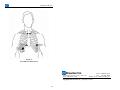
1
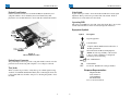
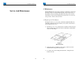
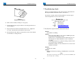
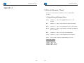
Braemar, Inc.
DL700
Operator Manual
Caution: U.S. Federal law restricts this device to sale by
or on the order of a physician.
Braemar Limited Warranty
Braemar products are warranted to be free from manufacturing and material
defects for a period of one (1) year from the date of shipment from Braemar to
the original purchaser.
Excluded from this warranty are expendable supply items including, but not
limited to, electrodes, leadwires, patient cables and batteries. This warranty does
not apply to any product that Braemar determines has been modified or damaged
by the customer.
Except for the express warranties stated above, Braemar disclaims all
warranties including implied warranties of merchantability and fitness.
The stated express warranties are in lieu of all obligations of liabilities on
the part of Braemar for damages, including but not limited to, special
indirect or consequential, arising out of or in connection with the use or
performance of Braemar products.
Any action for breach of warranty shall be commenced within one (1) year of
said breach or be forever barred. Any repairs made to the product that are not
covered by the warranty shall be billed to the customer.
Document Number: 600-0573-00
Revision: G
Date: March 2006
i
ii
Table of Contents
Product Overview .............................................................................................. 1
1. Description................................................................................................... 2
2. Specifications............................................................................................... 5
Product Operation ............................................................................................. 7
3. Recorder Preparation ................................................................................... 8
3.1 Battery Installation ................................................................................ 8
3.2 Setting the Clock .................................................................................... 8
4. Electrode Application ................................................................................ 10
4.1 Materials Needed ................................................................................. 10
4.2 Recommended Steps............................................................................. 10
5. Operation .................................................................................................. 12
5.1 Materials Needed ................................................................................. 12
5.2 To Start Recording............................................................................... 12
5.3 To Stop Recording ............................................................................... 14
5.4 Analyzing the ECG Data...................................................................... 14
Service And Maintenance................................................................................ 15
6. Maintenance............................................................................................... 16
6.1 Replacing the Clock Battery ................................................................ 16
7. Troubleshooting Guide .............................................................................. 18
7.1 Problem Description and Recommended Solution .............................. 18
8. Service Items.............................................................................................. 20
Appendix A ....................................................................................................... 21
9. Electrode Placement (7 Lead) .................................................................... 22
10. Electrode Placement (5 Lead) .................................................................. 24
iii
iv
DL700 Holter Monitor
DL700 Holter Monitor
1. Description
Product Overview
The DL700 Holter Recorder is a battery operated solid state recorder
designed for 24 hour continuous recording of ambulatory ECG data. It is an
AAMI Type I device, which is part of a conventional AECG monitoring
system where the ECG is recorded on a removable Flash memory card in the
DL700. After the ECG data has been recorded, the memory card is removed
from the DL700 and inserted in a Flash Card Reader which is part of the
Computer Analysis System on which the ECG will finally be analyzed. The
Flash memory card used in the DL700 is the same as some PCMCIA
memory cards used in laptop computers.
Batteries and Receptacle
The DL700 provides a battery compartment with secure receptacles for
inserting two standard AA alkaline batteries. A polarity guard feature is
built in to prevent damage in case the batteries are installed incorrectly.
Cover Labeling
The label on the outside of the cover provides information about the
company supplying the recorder while the label on the inside of the cover
provides Patient Hook-up and Recording Start/Stop instructional
information.
Digital Clock
A digital LCD clock is mounted into the front panel to provide both time
and date for patient convenience.
Clock Battery
The digital clock is powered by a Duracell silver oxide 392B, 1.5V battery
or its equivalent. For instructions on battery replacement, refer to the
Maintenance Section.
Clock Set Controls
The clock set controls are used to set the date and time. Time can be set in
hours and minutes.
1
2
DL700 Holter Monitor
DL700 Holter Monitor
Patient Event Button
Gain Switch
Patients should be instructed to use this Event Button anytime they feel
symptoms similar to those which they have been instructed by their
physician to note in their Patient Log along with date and time information.
A gain switch is provided to allow the medical technician to adjust signal
amplitude. Three positions are provided: 1/2X, 1X, and 2X. Position
indications are on the label above the switch.
Operating LED
This is the green LED just to the right of the gain switch (Fig 1). It provides
current status information on the recorder (See Operation Section).
Equipment Symbols
Symbol
Description
Type B equipment.
Consult manual.
0086
Complies with the Medical Device Directive of
the European Union.
Waste Electrical and Electronic Equipment
(WEEE) It is the responsibility of the end user
to dispose of this equipment at a designated
collection point for recycling.
Figure 1
DL700 Holter Recorder
Year of Manufacture
Patient Input Connector
The patient input connector provides a snug and reliable connection for the
patient electrode leads along with complete color-coding for each lead.
SN
REF
Serial Number
Not shown - DL700 is the catalogue number.
Test Jacks
Three test jacks are provided to verify that a good, reliable signal is being
obtained on each ECG channel immediately after connecting the electrodes
to the patient. This test should be done prior to allowing the patient to leave
the clinic.
3
European Representative:
CEpartner4U BV
Esdoornlaan 13
3951 DB Maarn.
The Netherlands
Tel: +31 (0) 6-516.536.26
4
DL700 Holter Monitor
DL700 Holter Monitor
2. Specifications
Functional
Channels
Resolution
Recording
Minimum Recording Time
Storage Medium
:
:
:
:
:
Download Interface
3
8-bit
Full disclosure
24 hours
Removable FLASH memory (Standard
PCMCIA-ATA card)
: PCMCIA card interface
Physical
Dimensions
Weight
Enclosure
Operating Position
Operating Temperature
Non-operating Temperature
Operating Humidity
:
:
:
:
:
:
:
6.00" x 3.50" x .95"
10 ounces with batteries
Molded plastic
Any orientation
0 C to 45 C
-40 C to 60 C
10% to 90% (non-condensing)
Electrical
Gain Settings: 1/2X, 1X, and 2X
Battery
: Two AA Alkaline (disposable)
Connector
: 7 pin (3 diff + 1 com), single lead wires
Test Jacks
: 3 channels
5
6
DL700 Holter Monitor
DL700 Holter Monitor
3. Recorder Preparation
Product Operation
3.1 Battery Installation
To ensure a full 24 hour recording it is essential to use new batteries before
each patient recording. The recommended batteries for the DL700 Holter
recorder are two AA alkaline batteries (IEC-LR6). When inserting the
batteries, follow the Start Recording procedure in the Operation section
while making sure to follow the polarity indication shown on the label in the
battery compartment.
- Note There is a built-in polarity guard feature to protect against damage to the
recorder but if the batteries are installed improperly, the unit WILL NOT
RECORD and the LED WILL NOT BLINK.
3.2 Setting the Clock
Time and Date on the digital clock can easily be set by the following
procedure using the two small access holes labeled "set" and "select". The
holes are located next to the Patient Event Button shown in Figure 1.
a)
Insert and press a pointed object into the top access hole, labeled "set",
to start the setting process.
b) Press the pointed object into the bottom access hole, labeled "select".
The digital display alternately shows the time and date.
c)
Press the bottom access hole a second time to select MONTH.
- Note Pressing the bottom access hole repeatedly, cycles the digital clock
through each selection - Month, Date, Hour, Minutes.
d) To set the current month, press the top access hole repeatedly to obtain
the desired month.
e)
7
8
Press the bottom access hole again to select DATE.
DL700 Holter Monitor
f)
To set the current date, press the top access hole repeatedly to obtain
the desired date.
DL700 Holter Monitor
4. Electrode Application
g) Press the bottom access hole to select the HOURS.
For safe and effective use, it is recommended that application of electrodes
be handled by trained medical personnel.
h) Press the top access hole repeatedly to set the correct hour in A.M. or
P.M.
i)
Press the bottom access hole to select MINUTES.
j)
Once again, press the top access hole repeatedly to set the correct
number of minutes.
Proper preparation of the patient's skin is absolutely essential to obtaining a
quality ECG recording.
- Note Without good skin preparation, both noise and artifact will frequently
degrade the patient’s ECG to the point of being unusable by the physician.
k) Press the bottom access hole to display the correct time.
4.1 Materials Needed
- Note If it is desired to have the Date and Time flash alternately - press the
bottom access hole after completing the previous step. Then, press the lower
access hole 5 times to set the colon flashing.
a)
For 3 channel recording, use seven (7) Silver-Silver chloride disposable
pre-jelled electrodes designed for 24 hour Holter monitoring. Do not
use 12-lead ECG or Stress Test Electrodes. Use electrodes designed
for longer term 24 hour monitoring.
b) 4 X 4 Prep Pads
c)
Isopropyl alcohol
4.2 Recommended Steps
a)
Select the sites for electrode application. The electrodes must be
applied over bone or cartilage. Refer to the Electrode Placement Chart
sections in Appendix A.
b) Wipe the skin in the electrode areas with an alcohol prep pad.
c)
After allowing the skin to dry thoroughly, locate the electrode
placement sites by palpation.
d) Dry shave body hair from the electrode sites.
e)
9
10
Using a small square piece of an abrasive material (220 grit sandpaper
or equivalent) and moderate pressure, abrade the skin at the electrode
sites by making 3 or 4 crossing strokes. The strokes should cross at the
chosen electrode site. Lightly brush the areas with a dry gauze pad to
DL700 Holter Monitor
DL700 Holter Monitor
remove any debris.
f)
5. Operation
Connect the color coded snap-on lead wires to the appropriate
electrodes before applying the electrodes to the patient.
5.1 Materials Needed
g) Once the backing is removed from each electrode, place it firmly on the
prepared skin surface site.
a)
h) In order to prevent the lead from tugging directly on the electrodes,
create a strain relief by looping each lead wire and placing a strip of
adhesive tape over the loop as well as on the electrode.
b) Two AA Alkaline (IEC-LR6) batteries.
c)
One Flash memory card with a storage capacity of 10 MB or larger.
The card requires no special formatting prior to its first use.
Patient Diary.
d) Recorder, either 5 or 7 lead patient cable, pouch or carrying case,
shoulder strap and belt.
5.2 To Start Recording
a)
Enter the patient’s personal data on the Flash memory card label
including the doctor's name, patient's name, and the date and start time
of the test. (A Sharpie, fine point, erasable marking pen is
recommended). This information should also be noted in the patient's
diary and the patient should then be instructed on how to fill out this
diary.
- Note Since the flash memory card is intended to be reused, the patient label
on the back side of the card has been designed to be easily erased so
that the next patient’s data can be written in the same area. Insure use
of an erasable marker.
b) Insert the Flash memory card into the recorder.
c)
The electrodes and lead wires should be attached to the patient as
specified in the previous section (Electrode Attachment). Once this has
been done, the lead wires must next be connected to the recorder
carefully following the color code above the input connector.
d) Install two fresh alkaline AA batteries.
- Caution All previous ECG patient data on the Memory card will be erased
immediately once the new batteries are inserted.
11
12
DL700 Holter Monitor
e)
The green operating LED will start to blink at a steady rate to indicate
normal operation. The LED will blink at this rate for up to 15 minutes
allowing time to verify that the signal on each channel is acceptable.
After this startup interval, the LED will begin blinking at a slower rate
to indicate that ECG recording has begun. The final blink rate will vary
somewhat depending on the storage capacity of the flash card and the
patient signal characteristics.
DL700 Holter Monitor
5.3 To Stop Recording
a)
- Warning DO NOT RE-INSERT BATTERIES after removal as this will erase the
ECG data on the Flash memory card.
- Warning If the LED is NOT BLINKING after the previous step, the unit is NOT
RECORDING. This LED is the only indicator that the recorder is
functioning properly and it should always be blinking whenever the unit
is recording. If it is not, please see the Troubleshooting Guide section.
f)
To insure that a good quality patient hookup has been achieved, a test
ECG output strip can be run on an ECG machine. To run a test strip,
connect a standard Test Box to the 3 recorder test jacks shown in Figure
1. Insert the plugs from the ECG machine into the Test Box. Run a test
output strip. Verify that there is an acceptable signal on each channel.
It may be necessary to adjust the gain by using the recorder gain switch
located next to the green LED shown in Figure 1. After selecting the
final gain setting, disconnect the Test Box from the recorder.
b) Remove the Flash memory card and patient electrodes. If it is desirable
to remove the leads from the patient input connector, then, due to their
snugness of fit in this connector, it is suggested that the medical
technician carefully grip these leads only at the base whenever
removing them. NEVER pull on the wire itself as this can easily break
the wire inside the insulation causing a noisy and intermittent ECG
recording.
5.4 Analyzing the ECG Data
a)
g) To abort the standard 15 minute startup interval once the
preparation is complete and it is desired to start the ECG recording,
hold the event pushbutton in until the LED stops blinking (usually about
5 seconds). Release the pushbutton and the LED will start blinking at a
slower rate, as described in Step e) above.
c)
Once the data transfer is complete, the previous patient’s name and any
other information written on the Flash memory card’s label should be
removed and the ECG data should be erased.
d) The Flash memory card is now free to be used for the next patient.
If there is a need to stop the recorder after the recording session has
begun, please refer to the following section “To Stop Recording”.
13
Insert the Flash memory card into the Flash card reader of the
Computer Analysis System on which the ECG analysis is to be
performed.
b) The Computer Analysis System must have special download software
installed to transfer the ambulatory ECG data from the Flash memory
card to the Analysis System.
h) Close the top cover of the recorder, place the recorder in the pouch, and
attach the recorder to the patient utilizing either the belt or the shoulder
strap. Caution the patient to avoid getting the recorder wet and to NOT
pull on the electrodes.
i)
To stop recording after 24 hours, or sooner if desired, remove the
batteries completely.
14
DL700 Holter Monitor
DL700 Holter Monitor
6. Maintenance
Service And Maintenance
The DL700 Holter Recorder requires virtually no maintenance. Ensure that
the battery contacts are clean and that the inside of the recorder is free of
dust and dirt. The case and the pouch with belt and strap can be cleaned
with a lint free towel moistened with mild soap and water. Do not use any
strong solvents. Clean as often as desired.
6.1 Replacing the Clock Battery
The digital clock uses one 1.5V silver oxide battery (Duracell 392B or its
equivalent). The battery has approximately a two year life. The battery is
accessed under the top cover.
a)
Open the top cover. Use a small jeweler's screwdriver inserted into the
exposed center screw on the back of the clock module to gently lift the
clock out of the endcap.
Figure 2
Removing Clock
b) Using the jeweler's screwdriver, remove the top small screw in the
metal holder that keeps the battery in place.
c)
15
16
Loosen the other screw holding the metal holder. Swing the metal
holder to the side.
DL700 Holter Monitor
DL700 Holter Monitor
7. Troubleshooting Guide
If there is a problem with the recorder, first review the “Typical Problem
Descriptions and Recommended Solutions” listed below.
If assistance is needed, call the following number for customer support
and/or arrangements for service of the recorder:
Braemar, Inc.
Figure 3
Replacing Clock Battery
1285 Corporate Center Drive, Suite 150
Eagan, MN 55121 USA
Phone:
800.328.2719
Fax:
651.286.8630
E-mail:
[email protected]
Web:
http://www.braemarinc.com
d) Remove the used battery and dispose of it properly.
e)
Position the new battery in place with the + side facing the direction as
shown in Figure 3.
f)
Reposition the metal holder and reinstall the first screw. Tighten the
two screws. Re-insert the clock module into the recorder.
7.1 Problem Description and Recommended Solution
Problem:
Green LED is not blinking.
Solution:
- Ensure that a Flash Memory card of at least 10 MB capacity has
been properly inserted in the recorder.
- Install a new set of AA alkaline batteries which are known to be
fully charged. New batteries MUST be used for each Holter
recording.
- Verify that the batteries are oriented according to the label in the
bottom of the battery compartment.
- Reinitialize by lifting one of the AA batteries for several seconds
and then re-inserting.
g) Reset the time and date. Refer to the Operations section of this manual
for information on setting the clock.
Problem:
Digital clock is blank
Solution:
Replace clock battery by referring to the Maintenance section in this
manual.
- Note The digital clock is independent from the operation of the DL700 and
does not affect the recording.
17
18
DL700 Holter Monitor
Problem:
Noisy ECG Recording
Solution:
- Ensure that all the electrodes are firmly and securely attached to
the patient. (Refer to “Electrode Attachment” section).
- Replace the entire lead set. (These leads are frequently broken
inside the lead insulation due to someone pulling on the leadwire
instead of at the base of the lead to remove it from the patient input
connector).
19
DL700 Holter Monitor
8. Service Items
Part Number
1
HeartStor card, 16 Mbytes
350-0147-01
2
HeartStor card, 32 Mbytes
350-0147-02
3
HeartStor card, 64 Mbytes
350-0147-03
4
Digital clock module
800-0364-01
5
Lead set, patient, 7 lead
200-1380-001
6
Lead set, patient, 5 lead
200-1380-002
7
ECG Test cable box
200-1588-001
8
Pouch with strap and belt
200-1508-001
9
Filler plugs
200-1586-001
10 Shoulder strap, pouch
100-1693-001
11 Belt strap, pouch
100-1694-001
20
DL700 Holter Monitor
DL700 Holter Monitor
Appendix A
9. Electrode Placement (7 Lead)
Seven color coded leadwires are utilized to create a 3 channel ECG
recording.
3 Channel Electrode Placement Chart:
White:
Channel 1 (-); Place on the right Manubrial border of the
Sternum.
Red:
Channel 1 (+); Place on the left Anterior Axillary line 6th rib.
Black:
Channel 2 (-); Place on the left Manubrial border of the Sternum.
Brown:
Channel 2 (+); Place at approximately 1 inch right of the Xiphoid
Process on the rib.
Blue:
Channel 3 (-); Place on the Center of the Manubrium.
Orange: Channel 3 (+); Place on the left Mid-Clavicular line 6th rib.
Green:
Ground; Place on the lower right rib margin over bone.
Channel Designation
Channel 1: White - Red
Channel 2: Black - Brown
Channel 3: Blue - Orange
21
22
DL700 Holter Monitor
DL700 Holter Monitor
10. Electrode Placement (5 Lead)
Five color coded leadwires are utilized to create a 2 channel ECG recording.
2 Channel Electrode Placement Chart:
White:
Channel 1 (-); Place on the right Manubrial border of the
Sternum.
Red:
Channel 1 (+); Place on the left Anterior Axillary line 6th rib.
Black:
Channel 2 (-); Place on the left Manubrial border of the Sternum.
Brown:
Channel 2 (+); Place at approximately 1 inch right of the Xiphoid
Process on the rib.
Green:
Ground; Place on the lower right rib margin over bone.
Channel Designation
Channel 1: White - Red
Channel 2: Black - Brown
Figure 4
7 Lead Electrode Placement
23
24
DL700 Holter Monitor
Figure 5
5 Lead Electrode Placement
Braemar Inc.
Phone: 800.328.2719
1285 Corporate Center Drive, Suite 150
Fax:
651.286.8630
Eagan, MN 55121 USA
E-Mail: [email protected]
Copyright 2006, Braemar Inc. All rights reserved
25