1
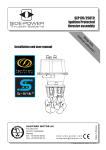
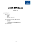
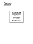
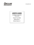
E
CARS Operating Instructions
Background: ECARS stands for Environmentally Controlled Aquatic Recirculating
Systems. They are 12 units located in room 151. Each system is made up of a double
drain tank with an external standpipe, a pump, a bubble washed bead filter, a UV sterilizer
and a temperature controller. Each system is computer controlled. There are twelve units
in this room. Access to tanks 1-6 is through the door 151a, for tanks 7-12 through door
151b. There are three boxes of relays on the wall inside room 151. These boxes hold 8
relays each and are associated with each of the three CL100's that control the ECARS in
this room.
System Description: The pump is controlled by the
Argus™ system and is plugged into a receptacle that
is wired through a relay that the Argus™ system can
turn on or off. A temperature sensor is located
directly above the pump in the outflow. This sensor
is set to alarm if the water temp rises above 25EC
(Pump Overheating Alarm). 25EC in a system
operating at 10EC would indicate that the pump is
cavitating. A cavitating pump will also cause a no
flow situation which will activate the No Flow Alarm.
If the system is to be run at higher temperature
(20EC) reset the pump overheating alarm to a higher
setting (35EC).
Magnetic Drive Pum p: NB arrow indicates
location of tem perature sensor
The pump draws water from an opening on the bottom of
the perimeter of the tank. This opening is protected by a
screen screwed into it. This screen can become clogged
by dead fish, debris and/or calcium. Situations where many
small dead fish or larger fish becoming caught on the
screen can cause a decrease in water available to the
pump. To avoid this situation the screen is sometimes mounted on a pipe that
elevates the screen into the water column.
The most commonly used pump in this room is a ¾ hp March magnetic drive pump model
TE-7R-MD. The most common problem exhibited by this pump is calcium build-up on the
ceramic spindle, which causes the impeller to stop turning. (See: Delim ing Magnetic Drive Pum p
Ceram ic Spindles and Im pellers) .
The filters: Water is pumped either through a Jacuzzi SherLok™ cartridge filter and a
bubble bead filter, just a bubble bead filter or in some instances no filter at all. The Jacuzzi
cartridge filters are installed on ECARS 7, 8 and 11. They contain pleated cartridges that
Page 1 of 22
require periodic cleaning. Pressure and flow
are monitored by Aqualab staff and recorded
in a spreadsheet on the Aqualab technicians
computer. When the pressure between the
pump and the filter rises 10 psi above the
initial (clean filter) pressure it is time to
replace the filter. (See: ECARS filter replacem ent
SOP) . The bubble bead filter acts as a biofilter
and is partially filled with floating plastic beads
water flows up through the filter and is
discharged into the UV sterilizer. The water
Jacuzzi SherLok Filter
inflow and outflow lines have swing check
valves to prevent accidental draining of the filter.
Bubble bead filter
The control / interface panel, located on
the temperature controller, is also plugged
N.B. even though the switch is turned
into a controlled receptacle. The SM12
off there is still power inside the
panel has been wired directly to the plug
control panel. Use caution when
so that it is powered even when the switch
working inside this panel.
for the control panel is turned off. The
SM12 requires power constantly to remain
in the Argus network. When the power fails
to the receptacle an Expansion Failure Alarm will sound. This alarm activates
immediately, a level 5 situation will exist
and an audible alarm will sound, the auto
The manual limit controllers in the
dialer will also be activated to notify
interface panels need to be reset after
personnel. (See Expansion Failure). The
Argus controlled environmental
Temperature Control Override for the
conditions are changed, usually at the
system is both electronic and manual. If
beginning of each new experiment.
the water temperature rises or drops
below a preset point, the control system
will cut all power to the controller.
Immediately the system will go into the highest alarm state and activate the Control
Override Alarm. An audible alarm will sound and the auto dialer will be activated to notify
personnel of the problem. Power will be restored when water temperature returns to normal
or by the Facility Manager. Operating in conjunction with the electronic control overrides
are manual temperature controllers. These manual controllers also act to cut power to the
ECARSystem during times of temperature extreme. There is one more electronic control
alarm. This is the Low Temperature Alarm, if for any reason the temperature drops below
5EC the system will enter into an alarm state. This alarm is to protect the system from
freezing and damaging the heat exchanger. There is also a Low Air Pressure Alarm on
the regenerative air system.
Power: 115V single phase: The ECARS pumps and interface panels are powered from
a single split duplex receptacle mounted in the walls or from 4 ceiling drops. Each
Page 2 of 22
receptacle is fed two circuits that are controlled by 115V 15 Amp relays (relays are found
in three boxes mounted on the north wall and labeled ARGUS). Each box controls 8
circuits or 4 ECARS. The relays are controlled by the Argus™ system. Each receptacle is
ground fault protected in the breaker panel. The circuit breaker panels are located on the
north wall in the. ECARS 1-6 are fed from the east panel and 7-12 are fed from the west
panel closest to door 151B. Please do not open this panel without proper
authorization.
250V three phase: The ECARS temperature controllers are powered by twelve 250V three
phase power cord drops. The circuit breakers for these feeds can be found in the panels
on the north wall between the doors. ECARS 1-6 are fed from the east panel and 7-12 are
fed from the west panel closest to door 151B.
Page 3 of 22
General and Daily Operational Instructions for the Use of ECARS in
Room 151
Record Keeping:
1:
2:
Daily Observation Sheets are located in a plastic sleeve mounted to the grey lid on
each ECAR unit. These sheets need to be kept up to date to reflect daily animal
care.
Mortality Sheets are also located in a plastic sleeve mounted to the grey lid on each
ECAR unit. When unexpected fish mortality occurs these sheets need to be filled
out.
Removal of Dead Stock:
1:
2:
3:
4:
5:
When mortalities occur they must be
Veterinary care is on a consultative
removed from the tank environment
basis only. Advice for the treatment of
immediately.
diseased fish may be sought from either
Deceased healthy fish may be
• Dr. John Lumsden (X54519) in the
disposed of by placing them into the
OVC Fish Pathology Lab
dead stock freezer located beside
• Dr. Roz Stevenson in the Fish Health
the walk-in freezer.
Lab in Microbiology (X52517)
Transfer dead fish to the freezer in a
• Dr. Marcus Litman (X58856) the staff
bucket labeled DEAD STOCK
veterinarian.
ONLY. Never carry dead fish
Prescriptions for the treatment of disease
through halls with a dip net. This
can be received from Dr. Lumsden or Dr.
practice promotes the transfer of
Litman.
disease.
If disease is suspected a post
mortem examination is necessary.
Please notify the Aqualab Manager of any concerns regarding disease.
Unexpected mass mortalities will require you to fill out an Animal Incident Report
and filing it with both the Aqualab Manager and the Animal Care Committee. Animal
Incident Report Forms are available for download on both the Aqualab Website and
the Animal Care website.
Daily Animal Care:
1:
Animals must be checked daily, this is an animal care requirement. If you are not
able to check animals on the weekends Aqualab offer a weekend checking service.
This checking can be facilitated by contacting Aqualab Staff and inquiring about
becoming involved in the program. There will be a cost associated with program
Page 4 of 22
2:
3:
4:
5:
6:
involvement.
Animals do not need to be fed daily.
Before or after feeding, the drain line to the tank needs to be flushed. This is
accomplished by opening the blade valve located on the floor between the two black
plastic upright pipes emptying into the trench. Open this valve by pulling the T
handle up and waiting about 5-10 secs. Watch the water flowing into the trench until
it runs clear. If this is done on a regular basis the whole process should not take
more than 5 sec. Once the water is clear close the valve by pressing down until the
valve is seated. If you are unclear of the proper actions to be taken contact
Aqualab staff for a demonstration.
Cleaning these tanks is not necessary on a daily or weekly basis. Due to the nature
of the tank and the flow within it, these tanks are self cleaning. The circular action
of the water flow, caused by the position of the return port at the top of the tank and
water lift caused by the airstone at the center, act to carry particulate wastes along
the bottom of the tank towards the center where it is sucked into the main drain line.
Due to this action the main drain must be periodically flushed. This is best
accomplished at the time of feeding.
Check water flow, water level, aeration and the bulb each time you check your
animals. If any of these this do not appear to be functioning properly contact
Aqualab Staff.
Check the UV sterilizer panel to ensure that the UV light is operational. Any power
fluctuation within the building will cause the UV bulbs to shut off. The units will
appear to be functioning properly, however the middle light labeled hrs will be
flashing. Press the green button located on the lower half of the panel to turn the
bulb back on.
At the beginning of an experiment:
Researcher responsibility:
1:
ECARS are flexible units for holding fish under predetermined environmental
conditions.
2:
It is the responsibility of the researcher to notify Aqualab staff of your intent to use
an ECAR unit. The cost is $5.00/day, $150/mo or $1500/yr.
3:
Environmental conditions that need to be set include: photoperiod, light intensity,
temperature, volume or intensity of flow, volume of make-up water, water depth.
4:
It is the responsibility of the researcher to ensure that these conditions are in place.
5:
Discuss with Aqualab staff alarm features and the parameters the alarms will be set
to. The researcher is responsible for any problems that arise if alarms are
disabled at their request.
6.
Under no conditions is the researcher authorized, required or expected to turn
components of the ECAR unit off (pumps, refrigeration unit, water valves, UV
sterilizer), unless they are properly trained by Aqualab staff. Training can only
be done by Aqualab’s permanent full time staff and must be recorded in the
training records.
Page 5 of 22
Failure to comply may result in damage to the equipment which will result in
replacement or repair of damaged equipment at the researchers cost.
Aqualab staff responsibility:
1:
Record start date.
2:
Set environmental conditions, photoperiod, light intensity, temperature, volume or
intensity of flow, volume of make-up water, water depth. (See ECARS initial Start-up, page
10)
3:
Enable all alarms: water temp deviation alarm, flow problems alarm, pump
overheating alarm, low water temp alarm.
4:
Set alarm parameters that are appropriate to experimental conditions. Temperature
deviations should be ±2EC. Flow problems should be 50%-25% of measured flow
at tank start-up. Pump overheating should be set to either 25EC when tank
temperatures are below 20EC and 35EC when tank temperatures exceed 20EC. Low
water temp should be set no lower than 5EC under normal conditions. In low
temperature conditions (below 5EC) consult the Aqualab Manager. Never disable
the low temperature alarm.
5:
Power the ECAR units on.
6:
Ensure the ECAR unit is in proper working order.
7:
Adust valves for researcher desired flow.
8:
Set manual limit thermostats within the ECARS Interface panel to ±8-10EC of the
Argus temperature setpoint.
9:
Record or reset hours on the UV sterilizer.
At the end of the experiment:
Researcher responsibility:
1:
Notify Aqualab staff where the experiment ends
2:
The researcher, in conjunction with the Aqualab staff, is responsible for cleaning
and disinfecting the system they are using.
3:
The researcher is responsible for disposal of experimental animals.
4:
The researcher is responsible for removing daily inspection and mortality records.
5:
The researcher is not responsible for turning the ECAR unit off.
Aqualab staff responsibility:
1:
Record the end date.
2:
Shut down ECAR unit in preparation for draining and cleaning (See ECARS Cleaning
page 11 and ECARS Final Shutdown, page 12 ).
3:
Disable alarms with the exception of the low temperature alarm.
4:
Reset manual limit thermostats within the ECARS Interface panel to -5EC and 20EC.
5:
Restart system for cleaning, disinfection and/or acid deliming.
6:
Flush, drain and turn unit off.
7:
Record hours of use on the UV sterilizer unit
Page 6 of 22
ECARS Maintenance
Deliming Magnetic Drive Pump Ceramic Spindles and Impellers
Equipment Required: 7/16" nut driver, aluminum punch, hammer, sink, acid bath, gloves,
eye protection,
1.
2.
3.
4.
5.
6.
7.
8.
9.
10.
Unplug the pump. Close the valves before and after the pump to stop water draining
out of the tank.
Using a 7/16" nut driver, remove the stainless bolts holding the face plate onto the
front of the pump.
Once the face plate is removed, insect the impeller to see if it move s freely on the
spindle.
If not, carefully pull the ceramic spindle with the attached impeller out of the face
plate.
Take the impeller, spindle, ceramic thrust washer and rear housing into the
workshop.
Using an aluminum punch and hammer carefully drive the ceramic spindle out of
the impeller.
Take the impeller, spindle, forward thrust washer and the rear housing and place
them into the acid delimer bath located in the workshop sink.
C
Be careful, acid delimer is corrosive.
C
Use gloves and eye protection.
Once the parts are completely delimed thoroughly rinse them in clear running tap
water.
Reassemble the pump. Open the valves that were closed previously. Plug the pump
back into the receptacle.
Make sure the pump is operating properly.
Deliming the Signet Paddlewheel Flow Sensors
The spindles of the paddlewheel flow sensors often
become calcified causing the paddlewheel to slow
or stop. To clean them you must first:
1.
Turn the water supply off.
C
On make-up lines you only need to
close the manual supply valve.
C
For the recirculation line you have to
unplug the pump and close the valve
located below the sensor.
2.
Carefully remove the sensor from the fitting,
there may be pressure behind the sensor
and you could get very wet.
C
If the water must be turned back on
Page 7 of 22
immediately, replace the sensor with a blank plug from the workshop.
3.
4.
5.
6.
7.
Carefully pry the paddlewheel out of the housing.
Without dropping either the paddle wheel or the spindle place them into a small cup
of acid delimer, and wait until it stops bubbling.
C
Be careful, acid delimer is a corrosive.
C
Use gloves and eye protection.
Once the paddlewheel and spindle are completely free of calcium rinse them in
clean fresh water and carefully replace the paddlewheel and spindle in the housing
without breaking the housing or losing the spindle.
Replace the sensor into the water line fitting making sure that the small arrows, on
the top of the sensor, are pointing in the direction of water flow (UP).
Restore the water flow.
ECARS Inline Filter Element Replacement and Cleaning
The Jacuzzi cartridge filters that are installed on ECARS 7, 8 and 11 contain pleated
cartridges that require periodic cleaning. Pressure and flow are monitored by Aqualab staff
and recorded in a spreadsheet on the Aqualab technicians computer. When the pressure
between the pump and the filter rises 10 psi above the initial pressure (clean filter) it is time
to replace the filter with a clean one and clean the dirty one.
A. Equipment Required:
- 1 small pair of channel lock pliers
- 1 replacement filter; kept in Rm.139 on top of the
black worm cooler
- 1bucket large enough to transport the dirty filter
N.B. It is not necessary to disable any alarms
because you will be bypassing the filter not shutting
off the pump.
B. Procedure:
Removal of the filter element:
1.
2.
Bypass water flow into the filter. Locate the
bypass ball valve. It is the only valve of the
three around the filter that is not immediately
connected to it. Fully open that valve and fully
close the other two valves. The filter should
now be isolated from the system and water
should not be flowing through the filter. Check
the tank to make sure water is still flowing.
Open pressure relief valve. Locate the yellow
drain valve on the top of the filter. Carefully
Page 8 of 22
Jacuzzi SherLok Filter: Red arrow
indicates bypass valve. Blue arrow
indicates location of pressure relief valve.
Green arrow indicates location of the drain
plug
rotate the valve counter clock-wise to release the pressure in the unit. Once the gauge
reads zero p.s.i., you are ready to drain the filter of water.
3.
Remove drain plug. At the base of the filter
look for a small black plug with a square head. Turn
the drain plug (with the channel lock pliers) counter
clockwise to loosen and slowly drain the filter
of water. Without removing the plug all the
way, let the rest of the water drain out
completely (it should take a couple of minutes).
4.
Remove locking ring. Locate the black
locking ring around the middle of the filter.
Depress the yellow tab on the lock ring to
unscrew the black ring in a counter clockwise
direction and lift it off the unit.
5.
Open the filter unit. Now the top half of the
unit shell can be removed. Gently (but firmly)
lift it up to reveal the filter element.
6.
Remove the filter element. Lift out the filter
element and put in the transport bucket. Make
sure that the black water distribution insert was
not removed with the dirty filter. If it was,
extricate it from the dirty filter and put it back
into the middle of the bottom section of the
filter body.
Open Filter: Red arrow indicates locking
ring N.B. yellow tab. Green arrow indicates
filter elem ent
Replacing and re-introducing the unit back into the
system:
1.
Replace the filter. Place the clean filter
element over the black water distribution unit.
2.
Put the filter back together. Carefully replace
the top half of the unit, and ensure that the oring is still in place around the base section of
the filter body. Slide the locking ring down
around the top half of the unit and rotate
clockwise until you hear a ‘click’. Do not over
tighten the lock ring.
3.
Fully disassem bled: Red arrow indicates
water distribution insert
Replace the drain plug. With the slip jaw pliers, replace the drain plug in the base
of the unit. Do not over tighten the plug.
Page 9 of 22
4.
Fill the filter with water. Locate, and slowly open, the ball valve between the tank
and the filter unit. This will begin to fill the inline filter with water. Allow a couple of
minutes for it to fill; water will flow out of the top of the yellow valve opening when
the unit is filled. Tighten the yellow valve to seal the unit and allow pressure to build
up in it again.
5.
Bring the filter online. Locate, and open, the ball valve between the inline filter and
the biofilter. You can now fully close the bypass ball valve. Water should now be
flowing though the filter. Check for leaks and that there is flow in the tank. Adjust
the flow with the pump side ball valve as is necessary for biological relevance of
what is in the specific ECARS.
6.
Establish pressure baseline. Once optimal flow is reached, record the initial
pressure of the filter from the gauge on the upper shell section. Aqualab staff will
monitor this pressure so that we know when it is time to change the filter.
Cleaning and storage of dirty filters. Take the dirty filter element in its bucket to Rm.
174. Take it outside and using the power washer, spray the filter element with domestic
water until it is clean. Make sure there is no waste trapped in the hollow core of the filter
element. After the unit is cleaned of debris place the filter element into a chlorine bath for
disinfection. Allow it to sit in chlorine for a minimum of 24 hrs before flushing. Once the unit
is flushed leave it out to dry (completely) and return it to its storage space above the black
worm cooler in Rm.139.
ECARS Initial Start-up, Disinfection and Final Shutdown Protocol
The purpose of this procedure is to provide supplemental information to Aqualab staff
trained in the procedure of starting up, cleaning and shutting down ECAR units. This SOP
is not to be used in place of personalized training.
ECARS Initial Start-up
1:
2:
Fill tank with water.
C
Go to the user screen in Argus and set make-up valve from Manual Off to
Manual On.
C
Check the manual raw water valve above the ECAR unit is open.
C
Make sure blade valve on drain line is closed.
Once tank is full, start pump.
C
Plug pump into controlled receptacle.
C
Check system ball valves are open.
C
Go to the user screen in Argus and set pump from Manual Off to Manual
On.
C
Check flow sensor.
C
Check flow in ECARS.
Page 10 of 22
3:
4:
5:
6:
7:
8:
9:
Set make-up water to Automatic.
C
Go to the user screen in Argus and set make-up valve from Manual On to
Automatic.
C
Set Volume to be Added to System. This volume needs to be experiment
specific.
Open chilled water valves to the refrigeration unit. There is a valve on each of the
chilled water supply and return lines. These need to be open prior to refrigeration
start-up.
Turn on refrigeration system.
C
Once flow is established the refrigeration system can be turned on by turning
the red switch located on the cover of the interface panel to the on position.
C
After the thermostats have cycled through the start-up phase check to
ensure appropriate high and low level limits are set.
C
This will also enable the incandescent lights.
If inline filters are to be used and are installed on the system, open filter valves and
close bypass valve.
Turn on UV sterilizer.
Turn on air to the tank.
On the Argus system:
C
Enable all alarms. Set appropriate temperature limits: ±2EC from setpoint for
deviation alarm.
C
Check photoperiod and intensity preference with researcher. Set
incandescent lights to Automatic and set intensity to a value that is
acceptable (see Set Intensity for Incandescent Lights).
C
Set Pump from Manual On to Automatic.
ECARS Cleaning
This protocol is for the purpose of supplementing the training procedure of acid washing
ECAR units. This SOP is not to be used in place of personalized training.
Acid Deliming system:
1:
2:
3:
4:
5:
6:
Before proceeding discuss procedure with Matt Cornish.
Open specific ECARS maintenance record and record shutdown date, volume of
foamtrol and acid added, initial pH, time acid in.
With the system full and running (see ECARS Start-up and Shutdown Protocol: Start-up) add 100
mls of Foamtrol and slowly add 4L of GE Betz KLEEN AC9513.
C
KLEEN is a strong acid, handle with care.
C
in tanks that have heavy deposits of calcium check for foaming, add
Foamtrol as required up to another 100 mls.
Set make-up water control to Manual Off.
Track pH over time.
Run ECAR unit until either the pH rises to 6 or until all calcium deposits have been
Page 11 of 22
7:
8:
9:
10:
11.
dissolved.
If necessary add acid in 1L increments until all calcium is dissolved.
Once calcium is removed check pH. If the pH is below 5 add sodium bicarbonate
to neutralize acid until pH is between 5-8.
Dump b of the water in the tank.
Set make-up water to Manual On and flush system for a minimum of 24 hrs.
Shutdown ECAR unit (see ECARS Start-up and Shutdown Protocol: Final Shutdown)
Disinfection with Chlorine Bleach:
1:
2:
3:
4:
4:
5:
6:
7:
Before proceeding discuss procedure with Matt Cornish.
Open specific ECARS maintenance record and record shutdown date, volume of
bleach added and rinse duration.
With the system full and running (see ECARS Start-up and Shutdown Protocol: Start-up) add
approximately ½ bottle of commercial Javex bleach.
Set Make-up water to Manual Off.
Allow system to run for a minimum of 4 hrs.
Dump b of the water in the tank.
Set make-up water to Manual On and flush system for a minimum of 24 hrs.
Shutdown ECAR unit (see ECARS Start-up and Shutdown Protocol: Final Shutdown).
ECARS Final Shutdown
Prior to final shutdown ECAR unit must be cleaned and disinfected. (See ECARS Cleaning)
1:
2:
3:
4:
5:
6:
7:
8:
9:
On the Argus User Screen:
C
Disable the Temperature Deviation Alarm, the Flow Problems Alarm and the
Pump Overheating Alarm. Do not disable the Low Temperature Alarm.
C
Reset the intensity of the incandescent lighting back to 50 if it was changed
(see Set Intensity for Incandescent Lights).
C
Set the make-up water to Manual Off.
Turn off the refrigeration system.
C
Set high limit thermostat to 20EC and low limit thermostat to 5EC.
C
The refrigeration system can be turned off by turning the red switch located
on the cover of the interface panel to the off position.
C
This will also disable the incandescent lights.
Turn off the air
Turn off the UV sterilizer.
Close the chilled water supply and return valves.
Unplug the Pump
Open the blade valve on the ABS drain line and drain the tank, leave blade valve
open.
If an inline filter is in place in this system close valves and open bypass. Drain filter.
Drain biofilter.
C
From the User screen open the waste valve.
Page 12 of 22
10:
C
Turn the refrigeration system On until the waste valve opens.
C
Once the valve is open turn the refrigeration system Off.
Set Pump from Automatic or Manual On to Manual Off.
Page 13 of 22
ECARS Alarm Situations
Water Temperature Deviation Alarm
There are 12 ECARS located in room 151. Each unit uses a compressor, a computer
controlled hot gas bypass valve and a heat exchanger to control water temperature. Chilled
water is used to dissipate excess heat from the control process.
Normal Operation:
There are two TN 6 thermistors
mounted in the system, one directly
on the pump outflow and one on the
heat exchanger outflow. The sensor
on the heat exchanger outflow is
used to control, monitor and alarm
the temperature within the tank.
During normal operation the heat
exchanger outflow is within ±2EC of
the setpoint temperature.
Alarm Situation:
If the temperature leaving the heat
exchanger deviates more than ±2EC
from the setpoint temperature for more than 15
min an alarm situation will occur. At 15 minutes
a Level 1 alarm will be activated and the alarm
within the building will start to sound. At 30
minutes a level 5 alarm situation will be
activated and the control system will start to call
numbers on the modem list. If the temperature
continues to either rise or fall the manual
overrides will be activated. The manual
overrides will either, shutdown the main
contactor for the ECARS (high temperature), or
shutdown the compressor, leaving the lights on
(if they were on) (low temperature).
What to do:
First check: How many units are in alarm? Is
the unit displaying other alarms? If several units
are in alarm, then there is a high likelihood that
there has been a chilled water or power failure,
Orange arrow indicates reset button
Page 14 of 22
in which case you will need to check and reset all of the ECARS and all of the chambers.
If there are other alarms, this alarm could be caused by a no flow situation. In which case
fixing the other alarms may fix this one too.
If only one unit is in alarm
you will need to check the
compressor.
The
compressors are located
behind the tanks. There
are two reset buttons that
may need to be pressed.
Press the white button
(orange arrow). This
should reset the
compressor, if there has
been a chilled water
failure. If this reset doesn’t
work, try the other reset
button this one can be
found inside the interface
panel on a manual
thermostat beside the high
and low limit thermostats
(green arrow). If this fails to start the compressor, then you will need to check the manual
overrides located inside the CTC interface panel.
Normal Operation (yellow arrow): the
indicator light on the front panel of the
A419 controller is ON.
If the lights for the chambers are not in the
normal position for the chamber, then the
temperature within the chamber is outside
of the normal operating parameters and
the chamber will not start until conditions
change. It is possible to change the upper
and lower limits of these controllers.
For the A419 controllers, the water
temperature in the heat exchanger
is displayed on the front of the
control panel (red arrow). Press
the menu button twice to display
the setpoint of the controller. To
change the setpoint press the up
Page 15 of 22
arrow (for the high limit) or down arrow (for the low limit). Set the limit ±5EC from the
room temperature. Press the menu button once to exit. The light should come on.
If the unit does not start up then you will have to check the Argus controls. For each ECAR
unit there is an Argus controller that also acts to limit the temperature deviation in the
water. This controller’s screen can be accessed through each rooms Output Equipment
Control menu.
To get to this menu select Factory Screens from the home page. Then select the
controller of choice e.g. C10 #151 1-4. Then select the unit that is having problems
e.g. ECARS #1. This will give you access to the unit’s Output Equipment Control
menu.
Selecting Output Equipment Control will give you a screen that shows all of the device
programs for that room. The output state for the Panel Control should read Manual On.
If the unit is off and the output state is Manual On you will need to call the Aqualab
Manager @ (519) 831-1671.
Pump Overheating Alarm
There are 12 ECARS located within Room 151. The recirculation system is composed of
a magnetic drive pump, a bubble washed bead filter and an ultraviolet sterilizer. The pump
is controlled by Argus. These pumps are thermally protected with TN6 thermistors installed
in the pipe close to the outflow of the pumps.
Normal operation
In normal operation the pump
temperature sensor (yellow arrow) will
read the tank water temperature. The
pump operates when temperature at this
sensor is within the normal operating
temperature range of the system i.e. the
water temperature is below 20EC for a
system running at 10EC. If normal
operating tank water temperature is
higher, then this sensor’s operating
temperature will be raised (but no higher
than 30EC). Water temperature is
controlled and also monitored by another
sensor located on the outflow of the heat
exchanger. This alarm is to protect the Magnetic Drive Pump
pump from damage caused by
overheating due to operating without water flow.
Page 16 of 22
Alarm Situation
If the recirculation pump gets vapour-locked, the intake pipe is blocked or the valves have
been turned off and water is no longer being pumped, the pump will heat up. As the
pump’s impellor spins without pumping water it will heat the water up inside the pump.
When the water temperature rises above 20EC (normal) - 30EC (maximum), an alarm
situation will exist. If this happens the pump will immediately shut down and a Pump
Overheating Alarm will be initiated, a secondary alarm the Low Flow Alarm will also be
initiated. Level one will occur after 5 minutes and will result in an audible alarm sounding
in the building. Level five will occur after 15 minutes and will result in the Argus system
activating the automatic dialer and modem list one.
What to do
If this situation occurs water flow must be restored to reduce the temperature in the pump.
Is this the only alarm? Try to find out why the pump is overheating.
1.
The pump lost prime and became vapour-locked.
If the pump has lost prime, you need to find out why?
•
low water level in the ECARS, these tanks are not protected with a
level sensor that will turn the pump off in the event of a low water
situation. Check the tank water level and the drain line valve. Also
check for any leaks in the system.
•
a leak in the inflow pipe can cause air to be sucked into the pump
resulting in the pump cavitating (this is an unlikely situation as the
pumps are below water level and should remain flooded at all times.
•
a blockage of the inflow line.
2
The intake pipe is blocked. Check the blue inflow screen in the tank and clean if
necessary.
One of the valves in the system is closed. Check all valves in the system, open as
necessary.
3
Once the problem is solved you may need to manually start the pump from the Argus
control system. This will cool the sensor enough for normal operation to resume. Once
water flow is restored this alarm (and any others e.g. Temperature Deviation, Flow
Problems) should reset.
If all of these options fail to restore flow you will need to contact the Aqualab Manager @
(519) 831-1671.
Flow Problems or No Flow Alarm
There are 12 ECARS located within Room 151. This alarm monitors the recirculation
paddlewheel flow sensor. The recirculation system is composed of a magnetic drive pump,
Page 17 of 22
a bubble washed bead filter, a temperature controller and an ultraviolet sterilizer. The pump
is controlled by Argus. Argus monitors a paddlewheel flow sensor mounted on the tank on
the return water line for the recirculation system. Water flow is vital for the survival of the
animals in the system, it removes waste products and uneaten food, and it maintains
temperature. Short durations of no flow are acceptable provided the low pressure air is on
and the tank has aeration.
Normal operation
Water is pumped from each tank into a cartridge filter (if one is inline)
and then a bead filter. The pump is controlled by the Argus system
and a manual override switch for Argus is located on the wall in the
corridor outside the room. The flow is monitored by a paddle wheel
flow sensor located on the side of the tank immediately prior to the tank
inlet. The alarm is set to wait 15 minutes before it activates to avoid
nuisance alarms.
Alarm Situation
An alarm situation will occur if flow past the sensor drops below 5
Paddlewheel flow sensor
L/min. A level one alarm will occur after 15 minutes and will result in an
audible alarm sounding in the building. A level five alarm situation will occur after 30
minutes of no flow and will result in the Argus system activating the automatic dialer and
modem list one.
What to do
The problem here could be one of many, first determine if the is pump is running or not.
Second if the pump is running is water flowing or not, always check. If the pump is running
and no water is flowing there is a high risk of the pump overheating and setting off another
alarm (Pump Overheating). If the pump is not operating, the damage may have already
been done or the pump has been shutdown by the pump temperature sensor.
Pump running:
1.
2.
3.
4.
5.
Flow may be cut off by closed valve. Check the valves in the system.
A valve may be closed within the filter loop.
C
Check the valves before and after the pump.
C
Check the valves before and after any inline filters.
C
Check the valve on the return line to the tank.
The pump may have lost prime and became vapour locked (i.e. air got into the
pump).
The intake pipe on the inside of the tank is blocked.
The flow sensor may be stuck, clogged with calcium (this happens in warm water
situations).
Page 18 of 22
6.
These pumps have magnetic drives and use a ceramic spindle as an axle for the
impeller, the spindle of the pump may have built-up calcium preventing the impeller
from turning.
Pumps not running
1.
The pump power circuit may be tripped. Open the grey breaker panel on the wall
and reset the breaker by switching it completely off then on again. The number for
the breaker is written on the receptacle the pump is plugged into.
2.
The pump may have overheated and seized, not all of the motors are thermally
protected. This will require complete replacement of the pump.
The major cause of this alarm is calcification of the pump spindle or the paddlewheel flow
sensor. The second most common cause of this alarm is that the intake line for the pump
inside the tanks is blocked or clogged.
If the problem is the paddle wheel flow sensor (see: Cleaning Paddlewheel Flow Sensors:
Signet on page 7).
If it is the impeller, you will need to replace the impeller, spindle and the inner
housing as quickly as possible. There are usually clean impellers in the workshop
or on the shelf in the storage room. If no clean impellers are available (see: Deliming
Magnetic Drive Pump Ceramic Spindles and Impellers on page 7).
If all of these options fail to restore flow you will need to contact the Aqualab Manager @
(519) 831-1671.
Expansion Failure Alarm
Argus is a network of smaller computers (CL100s) and one master computer. The master
computer is found in the Aqualab Office on the wall. This computer and all of the others
in the network is accessed by a desktop computer also located in the office. This computer
Page 19 of 22
is running Argus software version 3, the network edition. This version allows access to the
main server via the internet, however you must be running Argus ver 3 on your remote
computer to access the server. Each CL100 has a subnet composed of EX -16s and SM
-12s.
Normal Operation:
Under normal conditions these panels are supplied with 24V AC power. This power is
supplied by a class 2 transformer located in the interface panel. The communication
network for each panel can be checked the appropriate screen in the Argus program.
Alarm Situation:
If either the SM -12s or the EX -16s
loose power or these panels fail to
communicate an alarm situation will
occur. This will result in an immediate
Level 5 alarm and will result in the
Argus system activating the automatic
dialer and modem list one.
What To Do:
There are a number of likely causes for
power or communications loss that
results in an expansion failure.
Power loss:
•
Check the transformer feeding the panel (located inside the interface panel and
labeled Argus).
•
Check the power cord for the interface panel it should be plugged in.
•
Check the breaker to see if it is tripped, the breaker # is labeled on the receptacle
that the panel and the pump are plugged into.
•
Check Argus to see if the panel control is on.
To check the transformer, take a multimeter set for AC voltage and touch one probe to
ground and the other probe to a terminal on the transformer. You should get a reading of
~12+ Volts. Check the other terminal, the reading should be similar. If the readings are
below 12 Volts (e.g. 3 Volts) the transformer has failed and needs to be replaced.
To check Argus, log onto the server or another computer that can run Argus and:
Select Factory Screens from the home page.
Select the controller of choice e.g. C10 #151 1-4.
Select the ECAR unit that is in alarm e.g. ECARS #1.
Page 20 of 22
Select Output Equipment Control.
Selecting Output Equipment Control will give you a screen that shows all of the device
programs for that room. The output state for the Panel Control should read Manual On.
If it doesn’t, left click on the Manual Off or Auto Off and change it to Manual On.
If none of the above methods restores the alarm to normal function then the problem is
within the communications between the networked panels.
Communications loss
To check the status of the panel:
Select Factory Screens from the home page.
Select the controller of choice e.g. C10 #151 1-4.
Select Installation & Service Settings.
Select Device Network Communications.
The screen that will come up will indicate the devices on the network. The unit that has
failed will display not communicating in the status column and the timer will read 255.
There are a limited number of situations that can occur:
•
There is a problem with the wire between panels
•
The panel that is in alarm has failed
•
The panel before it in the network has failed
Page 21 of 22
Check the plug connections into and out of the panels, check the wires are in the correct
places e.g. the white or black wires are connected to the same terminals on both panels.
If all of these things have been checked and the problem still exists then it is probably the
panel that has failed. Replace the panel that is in alarm. If that still does not correct the
situation, replace the panel before it in the network.
If all of these options fail to start restore communications, you will need to contact the
Aqualab Manager @ (519) 831-1671.
Page 22 of 22