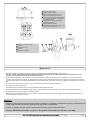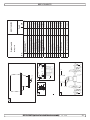
1
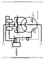
SIDE-POWER Thruster Systems is rd th a p bo ee n K al o u an m Installation and user manual SEP170/250TC Ignition Protected thruster assembly P.O. Box 519 N-1612 Fredrikstad Norway Tel: +47 69 30 00 60 Fax: +47 69 30 00 70 w w w. s i d e - p o w e r. c o m s i d e p o w e r @ s l e i p n e r. n o Made in Norway ! SLEIPNER MOTOR AS © Sleipner Motor AS version 1.0 - 2011 Contents Contents Technical specifications ......................................................... 2 Technical&specifications.............................................................. Planning important precautions ......................................... 32 Planning & important precautions.............................................. Stern thruster installation considerations ............................. 33 Stern thruster installation considerations................................... Bolt on installation .................................................................. 43 Bolt onon installation ..................................................................... Mould installation ............................................................... 54 Mould on installation .................................................................. Gearhouse and motorbracket ................................................ 65 Gearhouse and motorbracket. . ................................................... Oil tank & propellers .............................................................. 76 Oil tank & propellers.................................................................. Electromotor IP assembly ...................................................... 87 Electromotor IP assembly. .......................................................... 98 Electrical installation ............................................................... Electrical installation .................................................................. Control panel and control-leads .......................................... 109 Controlwiring panel diagram and control-leads............................................... 10 Visual ........................................................... 11 Visual wiring diagram............................................................... 11 Technical wiring diagram ..................................................... 12 Technical installation wiring diagram ......................................................... 12 Electrical of stern thruster systems ................... 12 Electrical installation of stern thruster systems ........................12 Checklist ............................................................................... 13 Checklist................................................................................... 13 Important user precautions .................................................. 14 Important user precautions. . ..................................................... 14 How to use Sidepower thrusters ......................................... 15 How to use Sidepower thrusters.............................................. 16 15 Maintenance .......................................................................... Maintenance............................................................................. 16 Troubleshooting .................................................................... 17 Troubleshooting. . ...................................................................... 17 Warranty statement ............................................................... 18 Warranty statement ................................................................. 19 18 Parts list ................................................................................ Parts list. . .................................................................................. 19 Service centres ...................................................................... 20 Service centres ........................................................................ 20 DECLARATION OF DECLARATION OFCONFORMITY CONFORMITY We, Sleipner Motor AS We, P.O. Sleipner Box Motor 519 AS N-1612 P.O. Box 519 Fredrikstad, Norway N-1612 Fredrikstad, declare that this product withNorway accompanying declare that thiscontrol productsystems with accompanying standard remote complies with the standardhealth remote control complies with the essential and safetysystems requirements according essential health and safety requirements according to the Directive 89/336/EEC of 23 May 1989 to the Directive 89/336/EEC of 23 May 1989 amended by 92/31/EEC and 93/68/EEC. amended by 92/31/EEC and 93/68/EEC. Technical specifications Technical specifications Motor: Motor: Gearhouse: Custom made reversible DC-motor. Custom made reversible Seawater resistant bronze.DC-motor. Ballbearing at propellershaft; combination of ballbearing and slide bearing at driveshaft. Seawater resistant bronze. Angular contact ball bearing at propellershaft and combination of ball bearing and needle bearing at driveshaft. Seawaterresistant aluminium. Propeller: Batteries: Batteries: Symmetrical 4 blade kaplan propellers, composite. Minimum recommended battery capacity fibreglass (cold crankreinforced capacity by DIN standard) SP 75 Ti IP 12V : 500 CCA DIN / 24V : 250 CCA DIN Minimum recommended battery capacity (cold crank capacity by DIN standard) SEP : 500 CCA CCA SAE SP 95170/250 Ti IP 12V24V : 700 CCA DINDIN/950 / 24V : 350 CCA DIN Max.use: use: Max. Safety: Safety: Up=to3continuous run7-10% time depending on load. run time shown onprotected control panel. S2 min. or appr. within a limited timeRemaining frame. All electromotors are against overheating. Electronic time-lapse device protects against sudden change of drive direction. Electric thermal cut-off switch in Electronic time-lapse device protects against sudden change of drive direction. Electric thermal cut-off electromotor protects against overheating (auto reset when electromotor cools down). switch in electromotor protects against over heating (auto reset when electro motor cools down). Flexible coupling between electro-motor and driveshaft protects electromotor and gearsystem if propeller gets Flexible jammed.coupling between electro-motor and driveshaft protects electromotor and gearsystem if propeller gets jammed. PJC panel shuts of automatically 5 minutes after last use (factory default). This interval can be adjusted in 5 min steps up to 60 minutes or turned off completly. The PPC Speed Control unit wil turn off motor power each time Ifmain original Sidepower panel is used, the panel shuts off for automatically 6 minutes afterinlast solenoids is activated. This removes any possibility solenoid lock in. Any fault the use. main solenoids will give feed back to the panel and turn off power to the electric motor. Integrated microprocessor monitors solenoids, reducing wear and risk of solenoid lock-in. Auto-stop of thruster in case of accidental solenoid lock-in or if run signal is continous for more than 3 minutes. Gearhouse: Motor bracket: Motor bracket: Seawaterresistant aluminium. Ignition protection: Conforms to ISO 8846 Ignition protection: Symmetrical Conforms to4ISO 8846 Propeller: blade kaplan propeller, fibreglass reinforced composite. Measure ments ref. SEP170/250TC SP75 Ti IP IP mm / inch 390mm 15.4" 299mm / /11,77" A 256mm / /10,08" B 340mm 13.4" 200mm / 7,87" 250mm 9.8" C 337mm / 13,3" D 350mm 13.8" ø300mm / /11,8" E ø300mm 11.8" ø200mm / /7,84" ø200mm 7.84" F 6xø10.5mm ø10,5mm // 0,41" G 6x 0.41" ø129mm 5.08" ø129mm / /5,08" H Inside 250mm 9.8" 185mm / 7,28" tunnel dia. Max. 60mm 54mm// 2.36" 2,13" stern thickness Motor 4,4 KW / 6 HP 8kW / 10.7HP output 12 / 24 Volt Voltage W.L. SP95 Ti IP B 407mm / 16,02" 256mm / 10,08" 200mm / 7,87" 337mm / 13,3" ø300mm / 11,8" ø200mm / 7,84" 6x ø10,5mm / 0,41" ø129mm / 5,08" C D 185mm / 7,28" 60° 54mm / 2,13" 4,4 KW / 6 HP Bolt holes dia: G Bolt position radius: H 12 / 24 Volt A Cut out in stern: F Outside of flange: E SP75Ti / SP95Ti ignition protected thruster assembly SEP170/250TC Ignition Protected thruster assembly Optional support (customer supplied) 1.2.1 - 2007 1.0 - 2011 2 2 Planning and important precautions Prior to installation, it is important that the installer reads this guide to ensure necessary acquaintance with this product. The thruster must NOT be installed in compartments that require ignition proof electric equipment. If necessary, make a separate compartment. The electromotor will generate some carbon dust so that any storage compartment must be separated from the thruster to prevent the stored items from becoming dusty/dirty. If you are installing the Sidepower in a small room /compartment, it should be ventilated to ensure cooling of the electromotor. If the height in the room you are installing the Sidepower is limited, the Sidepower can be installed horizontally or at any angle in between. - If the electro motor is positioned more than 30° off vertical, it must be supported separately. - The electromotor must be handled carefully. Do not lift it by the internal connections/main terminals or put it down on the driveshaft. - Beware to keep installation within advised measurements. No part of the propeller or gearhouse must be outside the tunnel. The electromotor, its components, contacts / plugs or other joints in the control cables must be mounted so that they will keep dry at all times. We advice to paint the gearhouse and propellers with antifouling. PS! Do not paint the anodes, sealings or propellershafts. Do not finish the inside of the tunnel with a layer of gelcoat / topcoat or similar. It is only room for a thin layer of primer and two layers of anti-fouling between the tunnel and the props. With the boat on land, only run the thruster for a fraction of a second, as without resistance it will accelerate very fast to a damaging rpm. Also, while the thruster is in air, make sure that the propellers have come to a complete stop before performing a directions change of the thruster, as it might cause damage to the thruster. The PPC Power control unit should be installed in a dry, ventilated place - cable connections facing down. Mount unit with battery positive cable branching out at unit terminal, not at thruster motor. Allow free space at min 200mm over and min 100mm in front and at sides.Take into consideration that a 5 m multicable shall be plugged in between thruster motor and PPC unit. This manual is intended to support educated/experienced staff and is therefore not sufficient in all details for the correct installation. Don’t install the electromotor at close range to easily flammable objects as it will reach over 100°C before the temperature switch is activated. Do not store items close to the thruster motor as it gets hot as well as any loose items near the thruster motor can cause problems with electrical wiring coming loose and short-circuiting. When installed in boats approved or classified according to international or special national rules, the installer is responsible for following the demands in accordance with these regulations / classification rules. The instructions in this guide can not be guaranteed to comply with all different regulations/classification rules. These instructions are only general instruction. If you are not skilled to do this work, please contact professional installers for assistance. NB! Faulty installation of the tunnel, thruster, PPC Power Control unit or panel will render all warranty given by Sleipner Motor AS void. Stern thruster installation considerations To achieve maximum effect, reliability and durability from your Sidepower stern thruster, a correct installation is very important. Please follow the instructions carefully, and make sure that all checkpoints are carefully controlled. Additional considerations for positioning of the stern thruster Make sure that the stern-tunnel does not disturb the waterflow under the hull Ensure that when installed the thruster does not foul exisiting equipment inside the boat like steerage links etc. Make sure that the water flow from the thruster are not intereferred to much by sterndrives, trimtabs etc. as this will reduce the thrust considerably. It is possible to mount the tunnel off the boat’s centre line if necessary. If the stern thickness is to much for the thruster in question you can easily remove hull material in the necessary area to fit the thruster. You only have to reduce the stern thickness down to the max. thickness measurement in the drawing. SEP170/250TC Ignition Protected thruster assembly 1.0 - 2011 3 SEALANT Fig. 2 Fig. 1 WASHERS LOCKNUT OR DOUBLE NUTS SEALANT Bolt on installation of the stern tunnel 1. Make sure that there are enough space both inside and outside the transom of the boat. 2. Once the place for the installation has been decided, hold the tunnel in place in the horizontal position and mark the bolt holes. Remove the tunnel and it is then possible to calculate and mark the centre. 3. It is important that the tunnel flange sits flush on the transom. If this is not so, then the area on the transom will have to be flattened to ensure a snug fit. PS ! Take care with grinders as it is very easy to remove to much in fibreglass At this time, cut out the centre hole and the transom to the same internal diameter as the tunnel flange and drill the bolt holes. Before bolting on the stern tunnel, the prepared area must be sealed with a gelcoat or similar to ensure there is no water ingress into the hull. If a bow thruster is also installed, we strongly advice to use separate battery banks for the two thrusters to avoid extreme voltage drop if both thrusters are to be used at the same time. Refer to the thruster manuals for adviced battery capacity and cable sizes for each thruster. Also ensure that you do not have direct connections of both + and - if you have built together controls for both thrusters to avoid current leakage between separate battery banks. If you are installing the standard Sidepower dual joystick panel this is already secured. 4. Before fitting the tunnel to the transom, fit the lower gear leg to the tunnel as described on page 6. We recommend that you fit the oil feed pipe also before the tunnel is bolted to the transom. 5. When fitting the tunnel, ensure that there is ample sealant (Sikaflex or similar) in the sealing tracks of the tunnel flange and around the bolts to make a water tight fitting (Fig. 1/2). Bolts, washers and nuts are not included as they will wary depending on the transom thickness We recommend A4 stainless with A4 lock nuts and A4 washers of a large diameter on both outside and inside. Bolts diameter: ø 10mm or 3/8” stainless steel 6. Refer to the installation manual for the recommended thruster fitting. SEP170/250TC Ignition Protected thruster assembly 1.0 - 2011 4 Fig. 1 Fig. 2 Grind off the bolt flange and the gelcoat both inside and outside in the areas shown. Boat transom Bond multiple layers both inside and outside Boat transom Stern tunnel Mould on installation of the stern tunnel 1. Make sure that there are enough space both inside and outside the transom of the boat. 2. Cut of the bolting flange on the stern-tunnel 3. Grind off the gelcoat both inside and outside the remaining “tube” atleast 10 cm down on the “tube” (Fig. 1). 4. Offer the stern tunnel to the desired position on the transom and mark around the tube. 5. Cut the marked hole in the transom of the boat. If a bow thruster is also installed, we advice to use seperate battery banks for the two thrusters to avoid extreme voltage drop if both thrusters were to be used at the same time. Refer to the thruster manuals for adviced battery capacity and cable sizes for each thruster. Also ensure that you do not have direct connections of both + and - if you have built together controls for both thrusters to avoid current leakage between seperate battery banks. If you are installing the standard Sidepower dual joystick panel this is already secured. 6. Grind off the gelcoat on the transom of the boat in an area of atleast 10 cm / 4” around the hole, both outside and inside (Fig. 1). 7. Offer the stern tunnel to the transom in the desired horizontal position, then bond to the transom with multi layers matt both inside and outside (Fig. 2). Take care not to reduce the internal diameter much, as this will make it more difficult to mount the thruster 8. Apply gelcoat or similar on all bonded areas. 9. Install the gear leg on the stern-tunnel as described in the installation manual for the thruster but fit the oil feed pipe first. 10.Basic installation of the motor assembly and electrical installation are described later in this manual. SEP170/250TC Ignition Protected thruster assembly 1.0 - 2011 5 Fig. 1 Fig. 1 SP 155 TCi SP 200 TCi SP75Ti Fig. IP 2 BOATS CENTRELINE GE O IL AR 90 P E TUNNELS CENTRELINE Ø 46,00mm 1,81" Bolt tightening force (4x): SP75Ti: 33 Nm (24lb/ft) lb/ft) 33Nm (24 Ø 11,00mm SP95Ti: 33 Nm (247/16" lb/ft) 3 4 Fig. 3 40,0mm 1,57" Bolt tightening force (2x): SP75Ti: 17 Nm (12,4 lb/ft) 33Nm (24 lb/ft) SP795Ti: 17 Nm (12,4 lb/ft) Fig. 2 SP 240 TCi SP 285 TCi 2 1 A Fig. 4 BOATS CENTRELINE Bolt tightening forces: TUNNELS CENTRELINE Bolts (4x) holding motor to bracket: 33 Nm (24 lb/ft) Bolts (2x) holding gearhouse to bracket: 33 Nm (24 lb/ft) Fitting gearhouse and motor bracket Ø 11,00mm 7/16" Ø 50,50mm 2" Fitting the electromotor IP assembly 48,0mm 1,89" 5. Prefill the gearhouse with gear oil type EP90 through the hole for the oildrain screw (4). Make sure to get the copper gasket (3) on again. 1. Remove the 4 bolts in tunnel the motorbracket. 6. Fit the lower-unit in the with the gasket inside the tunnel. Try on the propeller to make sure it is in the middle of the tunnel. If the tunnel is not plain, use some Sikaflex on or other sealant on the gasket to ensure that no leakages occur. 2. NB SP75 Only: Mount lower part of in thetoflexible ! Make sure that the no sealant gets the oil coupling holes (2).and tighten the set screws. Insert the "rubber/plastic ring" in this lower part. 7. Make sure that there isand some or greasebracket on Be thecareful, O-ringsthe in the motor bracket before mounting it together the gearhouse, as no D Fitting gearhouse motor Getriebe und with Motorhalterung 3. Place the motor gently on theoil motorbracket. motor is heavy! lubrication couldthat cause damagering" to the O-rings. SP75: Ensure the serious "rubber/plastic goes into position. SP95: Ensure kay on axle is aligned with keyway in oneand piece coupling 8. Push the gearhouse through the main hole in the tunnel push the and motor-bracket gently together. 1. gearhouse Die Mittellinie von Tunnel und Boot markieren. Die Propeller ark the centreline of the tunnel and the boats. The propellers Ensure that you are placing the motor so that the cable terminals on it are available for electric installation later. die bolts. Getriebeeinheit dürfen nicht aus dem Tunnel herausste d the lower unitthe must beunit completely inside thetogether tunnel. with the two provided 9. Screw lower and the motor-bracket Fasten thecentre bracketof with 4 bolts anddouble tigthen them. 2. Die Löcher mit der Dichtung (A) markieren. Maße überprü se the 4. gasket (A)the to motor mark tothe thetheholes and NB position, ! Da derthe Abstand zwischen und Tunnel minima eck the electromotor needsPropeller a separate/additional 5. measurements. If you are installing a SP95Ti IP in an angle of more than 45o off a vertical müssen für eine präzise Installation alle Löcher auf der Mit B ! All holes must be in-line with the tunnels' centreline for support. See illustration in the measurements drawings. linie des Tunnels liegen. ecise installation, as the clearance between the propeller and 6. is SP75 Only: Lift the lower part of the flexible coupling together with the rubber/plastic ring into the upper flexible coupling. The e tunnel minimal. Bereich Motorhalterung rubber/plastic ring must be in its correct position in the upper part,3. fullyIm inserted but der not compressed againstdarf it (17kein mm).Laminat auf dem Secure the lowerwhere part of the the flexible set-screws. Tunnelthesein, da dies zu einem Getriebeschaden führen ka ere must be no casting motor coupling bracketinisitstonew be position by tightening Liegt die Motorhalterung nicht eben auf dem Tunnel auf, s aced, as this will cause possible failure of the gearhouse. The sind sämtliche Unebenheiten in diesem Bereich abzuschleife otor bracket must fit steady on the tunnel, if the tunnel is not mooth, all bumps or uneven parts must be grinded smooth. Final gearleg assembly 4. Erst das Hauptloch, dann die beiden Bolzenlöcher bohren ill the main hole and then the two screw holes. 5. Das Getriebegehäuse mit Getriebeöl EP90 durch die Öffn der Ölablaßschraube (4) befüllen. Kupferdichtung (3) einsetz efill the gearhouse with gear oil type EP90 through the hole the oildrain screw (4). Make sure to get the copper gasket NB ! Paint the gearhouse and propeller with antifouling for propellers to prevent growth of barnacles or similar which would reduce the 6. Das Getriebegehäuse unter Verwendung der Dichtung in ) on again.performance dramatically. Do not paint the propeller shaft, the zincanodes or the end face of the gearhouse. Tunnel einpassen. Den Propeller auf die Achse stecken. Is Tunnelinnenseite ungleichmäßig, etwas Sikaflex o.ä. auf die the lower-unit in the tunnel with the gasket inside the tunnel. DIchtung auftragen, damit keine undichte Stelle auftritt. y on the propeller to make sure it is in the middle of the NB ! assembly Die Durchgänge für das Öl (2) von Dichtmasse freiha nnel. If the tunnel is not plain, useSEP170/250TC some SikaflexIgnition on or other Protected thruster 1.0 - 2011 6 alant on the gasket to ensure that no leakages occur. 7. Etwas Öl oder Fett auf die O-ringe der Motorhalterung geb B ! Make sure that no sealant gets in to the oil holes (2).protected thruster assembly 1.2.1 - 2007 8 SP75Ti / SP95Ti ignition 5 1 2 3 4 Locktite Fitting propellers 1. Push the propeller onto the shaft, carefully rotate the propeller until the drive pin aligns and moves into the slot/grove in the propeller hub. There should be almost no gap (approximately 1mm) between the propeller hub and the gear house. 2. Place the washer (4) on the propeller shaft and then tighten the lock-nut (3) on the propeller shaft. 3. Place the zinkanode (2) in its designated position and tighten the anodes holding screw (1). Apply a thread glue (Locktite or similar) to ensure that the anodes holding screw does not un-screw itself from the propellers rotation. 4. Fit the propellers to the shafts with the LH marked propeller on the port side and the RH marked propeller on the starboard side. Turn them to again make sure they move freely and as much in the centre of the tunnel as you have managed. Parts description: 1: Screw for anode 2:anode 3: Propeller lock nut 4: Washer 5: Drive pin for propeller SEP170/250TC Ignition Protected thruster assembly 1.0 - 2011 7 e (4x): ft) ft) Fig. 2 Fig. 1 e (2x): lb/ft) 4 lb/ft) SP95Ti IP Key in driveshaft Fig. 2 SP 200 TCi SP 240 TCi SP 285 TCi Driveshaft from gearhouse Set screw Keyway in flexiblecoupling SP75Ti 88mm For safety the motor of the Sidepower SP200TCi / SP240TCi / SP285TCi must be fastened in all installation positions with the included motor-support. 1. 2. Flexible-coupling 3. Fit the motor to the already fitted motorbracket on the tunnel. Fasten the support to a bulkhead / the boat in a correct position to support the motor firmly. The support can be fastened anywere on the motor as long as it does not interfer with the cables, but we do advice to fit it on the top as shown in these drawings. Be sure to use the included rubber strip between the support and the motor. Bolt tightening SP 200 TCi SP 240 TCi SP 285 TCi force (4x): SP75Ti: 33 Nm (24lb/ft) lb/ft) 33Nm (24 SP95Ti: 33 Nm (24 lb/ft) ectromotor IP assembly Fig. 3 Bolt tightening force (2x): SP75Ti: 17 Nm lb/ft) 33Nm (24(12,4 lb/ft) SP795Ti: 17 Nm (12,4 lb/ft) the set screws (two for SP75Ti IP, one for SP95TI IP). Insert the "rubber/ then them. han 45o off a vertical position, the electromotor needs a separate/additional gs. 88mm , the motor is heavy! Ensure that the "rubber/plastic ring" goes into position. e terminals on it are available for electric installation later. 212mm the rubber/plastic ring into the upper flexible coupling. The rubber/plastic ring serted but not com-pressed against it (SP75Ti IP:17 mm - SP95Ti IP: 2mm). position by tightening the set-screws (two for SP75Ti IP, one for SP95TI IP). GB D IP assembly Fitting the electromotor Fitting the electromotor Einbau des Elektromotors 1. Remove the 1. the 44 bolts bolts in in the the motorbracket. motorbracket. 1. Die 4 Bolzen in der Motorhalterung enfernen. gearleg2. 2. DieInsert Antriebsachse im Getriebegehäuse und die Motorachse so Mount the lower part flexible coupling and thighten the red "plastic ring" in the lower part 2.assembly Turn the driveshaft in of thethe gearhouse and the motorshaft sothe theset screw. die elastische Kupplung dazwischen paßt. ring" key in the the keyway in driveshaft the flexibleand coupling are in-line. 3. Place the shaft motorand gently onto the the motor bracket. Be drehen, careful, daß the motor is very heavy! Ensure that the "plastic 3. cable Den Motor vorsichtig auf die for Motorhalterung aufsetzen. Ensure are placing themotor motor so that the terminals are available electric installation later.Der 3. goes Placeinto the position. motor gently ontothat the you driveshaft and the propellers to prevent growth of barnacles similariswhich reduce the Motor ist sehr schwer! Fitting the electromotor IP ass bracket. Bemotor careful, theormotor verywould heavy! 4. Fasten the loosely to the bracket with the provided bolts. haft, the zincanodes or the end face of the gearhouse. 4. Mit den 4 Bolzen Motor und Motorhalterung lose verschrauben. 4. Tighten Fasten the loosely to the the motor brackettowith provided bolts. 5. themotor 4 bolts holding the the motorbracket. 5. Abmessen und part die beiliegende Motorabstützung anbringen, 5. Lift Measure up and support so that 6. the lower partfitofthe theprovided flexible motor coupling together withthe the plactic ring into the upper of the fleixible coupling. Theso plastic ring daß der Motor anliegt.it Die Abstützung gut am Boot bemotorbe sitsintightly in it. The support must be sturdily fastened to but not compressed must its correct position in the upper part, fully inserted, against (2mm). Secure muß the lower part of the werden. Diemotorbracket. beiliegende Gummiplatte vor dem festthe boat. in Make sureposition to put the rubber between the coupling its new by provided tightening the set-screw. 1. Remove festigt the 4 bolts in the zwischen und Abstützung supportthe andsystem the motor before the tightening the itstrap. 7. Check by turning propeller, will be a little hard to turnziehen (because of the Motor gear reduction and thebringen. motor), but you Mit den 4 Bolzen Motor und -halterung miteinander verschrauben. 6. should Tightenbe theable 4 bolts holding motor to the motorbracket.2. SP756.Only: to turn it bythe hand. Mount the lower part of the flexible coupling and tighten the set scre o 7. Die Befestigungsschraube im unteren Teil der elastischen 7. Tighten the set-screw in the lower part of the flexible coupling. 8. If you areassembly installing the 8 than 45 off a vertical position, the electromotor assembly needs a seperate/ protected thruster 1.2 thruster - 2005 in an angle of more festziehen. See illustration on previous 8. additional Check the support. system by turning the propeller, it will page be a little3.hardPlace theKupplung motor gently on the motorbracket. Be careful, the motor is heavy! Überprüfen, sich die Propeller im into Tunnel drehen lassen. to turn (because of the gear reduction and the motor), but you SP75:8.Ensure that theob"rubber/plastic ring"frei goes position. Aufgrund der Getriebeübersetzung und des Motors sollte das should be able to turn it by hand. In some cases (shallow installation or workboat / fishingboat only) we recommend to protect the propeller by mounting a grid in the tunnel SP95: Ensure kay on axle is aligned with keyway in one piece coupling Systemdies etwas schwergängig sein. opening (Fig. 3). It is important to keep a grid to a minimum and Ensure as streamlined for the thrusters waterflow as possible, as it will dethat you are placing the motor so that the cable terminals on it are avail crease effect of theinstallation thruster. or workboat / fishingboat only) we In somethe cases (shallow In manchen Fällen, z.B. bei flachem Rumpf oder im gerwerblichen recommend to protect the propeller by mounting a grid in the tunnel 4. Fasten the motor to the bracket with the 4 bolts and tigthen them. Einsatz (z.B. Fischfang) empfehlen wir, den Propeller durch ein opening (Fig. 3). It is important to keep a grid to a minimum and as vor der Tunnelöffnung zu schützen (Fig. 3). Dieses osollte auf streamlined for the thrusters waterflow as possible, as it will gearleg Gitter Final assembly 5. If youein areMinimum installingbeschränkt a SP95Ti IP angle of more than 45 off asein, vertical posit undinsoanstromlinienförmig wie möglich decrease the effect of the thruster. See illustration in the or measurements drawings. da ansonsten Leistung des Thrusters wird. the Paint the gearhouse and propeller with antifouling for pro-pellerssupport. to prevent growth ofdie barnacles similar whichreduziert would reduce performance dramatically. Do not paint the shaft, the or the Lift endthe face of the gearhouse. NB ! Paint the gearhouse and propeller withpropeller antifouling for pro6. anodes SP75NB Only: lower part theGetriebegehäuse flexible coupling Anti-Fouling together with the rubber/pla ! Wir empfehlen, auf of das pellers to prevent growth of barnacles or similar which would rubber/plastic ring must be in its correct position in the upper part, fully inserted aufzutragen. Nicht auf die Propellerachse, Zinkanoden oder reduce the performance dramatically. Do not paint the pro- Secure the lower part of the flexible coupling in its new position by tightening th den Verschluß des Getriebegehäuses auftragen. peller shaft, the zincanodes or the end face of the gearhouse. NB ! Den Thruster nur für den Bruchteil einer Sekunde betätigen NB! Do not run the thruster for more than very short bursts withwenn dieser nicht im Wasser ist. out not being thethruster water. for more than very short bursts with-out being NB ! in Wird Elektromotor eingebaut, falls das Boot noch in Bau NB! Do runinthe theder water. ist, so muß dieser abgedeckt werden, um eine Verschmutzung NB ! If the boat is still being built when the electromotor is installed, it Final gearleg assembly NB ! If the boat is still being built when the electromotor is installed, it must be von covered upund to avoid from the building going into the Relais Motordust zu verhindern. Diese Abdeckung muß must be covered up to avoid dust from the be building goingbefore into the thruster is motor and the solenoids. This cover must removed being used. vor Benutzung des Thrusters entfernt werden. the motor and the solenoids. This cover must be removed before the thruster is being used. NB ! Paint the gearhouse and propeller with antifouling for propellers to prevent grow performance dramatically. Do not paint the propeller shaft, the zincanodes or th 14 SP 155 TCi / SP 200 TCi / SP 240 thruster TCi / SP 285 TCi 2.51.0 - 2006 SEP170/250TC Ignition Protected assembly - 2011 8 Fig. 1 NB: The Proportional Power Controller is a bulkhead (wall) mounted unit and must be installed in a dry and well ventilated compartment. The unit also requires a 200 mm minimum head clearance and a 100 mm minimum clearance surrounding its remaining outer casing. 4X Min. 200mm Proportional Power Controller PPC 800 190x300x145mm (w x h x d) MOTOR PPC Thruster Battery 12/24V + Battery B Fuse 12V or 24V Manual or automatic Main switch Min. 100mm *D 100mm M + SP 75 Ti SP 95 Ti SP 125A Ti Min. *C Fig. 2 - S-link control cables See page 15 5m fixed multicable C D E <5m Fig. 1 Table for s election of m ain cable, battery, fus e and m ain-s witch s izes . V oltage Cur r e nt dr aw SEP170/250TC 12 V 24V 480 A 550A 12V Extr .batt * 300 A SP 75 Ti M ode l up to 7m total +& - 2 50 mm2 550550 CCA C C ADIN D in 50mm 1045CCA C C ASAE SA E OO 1045 N/A SP 95 Ti SP 125 Ti - 2 550550 95 mm2 CCA DIN CC A D in 70mm 1045 C C ASAE SA E OO+ 1045 CCA OOO+ 50 mm2 O 35 mm2 340 A +& 14 - 21m total +& - 21 - 28m total +& - 28 - 35m total +& - 36 - 45m total +& - M in. Cable M in.Batte r y M in. Cable M in.Batte r y M in. Cable M in.Batte r y M in. Cable M in.Batte r y M in. Cable M in.Batte r y M in. Cable M in.Batte r y dim e ns ion CCA by DIN dim e ns ion CCA by Din dim e ns ion CCA by DIN dim e ns ion CCA by Din dim e ns ion CCA by DIN dim e ns ion CCA by Din 300 C C A D in 240 APPC800 is a bulkhead 24 VController The Proportional Power 570 CC A SA E 2 (wall) mounted unit and must be installed in a dry and well 70 mm2 750 C C A D in ventilated compartment.The unit 680also A requires a 200mm 12 V 1425 C C A SA E OO+ minimum head clearance and a 100 mm minimum 12V N/A 400 A outer casing. clearance surrounding its remaining Extr .batt * 24 V 7 - 14m total Thruster motor Fig. 2 50 mm2 O 400 C C A D in 760 CC A SA E 35 mm2 2 105 mm2 OOOO 70 mm2 OO+ 50 mm2 O 2 550550 CCA DIN 120 mm2 C CA D in 70mm 1045 C C ASAE SA E OO+ 1045 CCA OOOO+ 300 C C A D in 570 C CA SA E 70 mm2 300 C C A D in 570 C CA SA E 50 mm2 750 CC A D in 1425 C C A SA E 150 mm2 350 C C A D in 665 C CA SA E 95 mm2 400 C C A D in 760 C CA SA E 70 mm2 OO+ O 2xOOO OOO+ 2 600600 CCA DIN 150 mm2 CCA D in 90mm 1140 C C ASAE SA E OOO+ CCA 2xOOO 1140 300 C C A Din 570 C C A SA E 95 mm2 300 C C A Din 570 C C A SA E 70 mm2 750 C CA D in 1425 C C A SA E 175 mm2 350 C C A Din 665 C C A SA E 120 mm2 400 C C A Din 760 C C A SA E 95 mm2 OOO+ OO+ 2x OOOO OOOO+ ElectricalOO+ installation OOO+ • Explanation of electrical table - All cable lengths are the total of A+B+C+D+E in Fig. 1. GB Electrical installation - Battery size is stated as minimum cold crank capacity, not Ah. Use slow fuse rated to table hold stated Amp-Draw for min. 5 minutes. • -Explanation of electrical D N / A 2 600 CCA DIN 100mm OOOO 1140 CCA SAE 350 C C A D in 665 C C A SA E 120 mm2 350 C C A D in 665 C C A SA E 95 mm2 750 C C A D in 1425 CC A SA E N/A 350 C C A D in 665 C C A SA E 150 mm2 400 C C A D in 760 C C A SA E 120 mm2 OOOO+ OOO+ 2x OOO OOOO+ / A2 600 CCA DIN 120Nmm OOOO+ 1140 CCA SAE 350 CC A D in 665 C C A SA E 150 mm2 350 CC A D in 665 C C A SA E 120 mm2 2x OOO OOOO+ 350 C CA D in 665 CC A SA E 350 C CA D in 665 CC A SA E N/A 350 CC A D in 665 C C A SA E 180 mm2 450 CC A D in 855 C C A SA E 150 mm2 2xOOOO 2x OOO 350 C CA D in 665 CC A SA E 450 C CA D in 855 CC A SA E Elektrische Installation • Übersicht: - All cable lengths are the total of + and - (to and from). - Leitungslängen beziehen sich auf die Gesamtlänge von + und • It important thatisyou use as a good cable cold size and batteries with a high capacity to feed the thruster, because it is the nicht actualAh. voltage at the - is Battery size stated minimum crank capacity, not Ah. cranking - Batterieangabe ist min. Kaltstartkapazität, motor while the thruster decides the output rpm 5ofminutes. the motor and -thereby the actual thrust. Please see the list below for advised - Use slowrunning fuse rated to hold that stated Amp-Draw for min. Sicherung: träge Ausführung; angeg. Stomverbrauch min.min. 5 Min. sizes of cables Yousize can when of course use larger cables for even better results. * Cable size and batteries. main battery an extra bow battery with * Kabelund Batteriegröße, falls eine zusätzliche Batterie, mit min. minimum the CCA mentioned as A is installed. der Kaltstartkapazität (mit A angegeben), im Bug installiert ist. • A It is important thatcan youtake use the a good and batteries • main switch that load cable withoutsize noticeable voltagewith dropa must be in the main positive leadanliegende so the power for the thruster can be • installed Da die am laufenden Motor Spannung die Umdrehigh cranking capacityoftothe feed the thruster, the actual This should turned off independent rest when not onbecause board oritinisemergencies. be placed in an easy accessible place and the boats hungszahl und damit die Leistungskraft bestimmt, sind instrucKabel mit voltage at the motor while theturned thruster decides tions should inform that thisrunning should be off that like the boat’sthe other main switches. ausreichendem Querschnitt und Batterien mit hoher Stromoutput rpm of the motor and thereby the actual thrust. Please see kapazität zu verwenden. Bitte die unten angegebenen Mindestthe also list below sizes cableslead andforbatteries. You can shortgrößen fürofKabelquerschnitt undfuse Batterien • We advicefor toadvised install a min. fuse in the of positive protection against circuiting the main cables. This should berücksichtigen. be of a adequate quality of course use larger even better results. Natürlich noch bessere Leistung überdimensionierte which normally meanscables that it for is physically large as these have less voltage drop than thekönnen simple /für small ones. It should be of the slow type and sized • to A main switch (*C) that canfortake the load without noticeable voltage Bauteile verwendet werden. take the amperage draw at least 5 minutes. drop must be installed in the main positive lead so the power for the • Auf der positiver Hauptseite muß ein Hauptschalter (*C) mon-tiert thruster can be turned off independent of the rest when not on board werden, die897724 Leistung ohneThe größeren Spannungsverlust • It is highly recommended to install a Sidepower Automatic Main Switch 897712 (12V)der eller (24V). AMS will be activated when the or in emergencies. This should be placed in an easy accessible weiterleitet. die Spannung für den Thrustertointhe Notpanel is turned on, contains an automatic short circuit fuse and a manual emergencyDamit stop. kann The AMS will also provide feedback place and the boats instructions should inform that this should be fällen abgeschaltet werden, ohne die übrige Bordelektrik zu bepanel regarding evt. faults. turned off like the boat’s other main switches. einflussen. Dieser sollte an einer leicht zugänglichen Stelle pla-ziert • We also advice to install a fuse (*D) in the positive lead for protection sein und die Anleitung darauf hinweisen, daß dieser wie die andere • The cable ends must be fitted with terminals and these must be well isolated against contact with anything but the proper connection point. against short circuiting of the main cables. This fuse should be of a Bordelektrik bei Nichtbetrieb abgeschaltet werden sollte. adequate quality which normally means that it is physically large as • Zum Schutz gegen Kurzschlüsse empfehlen wir, in der positiven • Terminals must properly tightened. inner nut when tightening (Fig. 2). Tighten ø10mm / 3/8" 15 Nm/11lb/ft. these have lessbe voltage drop than theSecure/hold simple / small ones. It should Leitung eine Sicherung (*D)bolt zu with installieren. Es sollte eine be of the slow type and sized to take the amperage draw for at least Qualitätssicherung von ausreichender Größe verwendet werden. 5 minutes. Die Sicherung sollte in "träger" Ausführung sein und die • A circuit breaker can be used instead of the fuse and main power angegebene Amperezahl mindestens 5 Minuten aushalten. switch as long as the functionality is the same. • Statt Sicherung und Hauptschalter kann ein Sicherungsautomat • The cable ends must be fitted with terminals and these must be well verwendet werden, falls die gleiche Funktionalität gewährleistet ist. isolated against contact with anything but the proper connection • Die Leitungsenden müssen so mit Kabelschuhen versehen und point. isoliert sein, daß sie nur mit dem Terminal Verbindung haben. • Terminals must be properly tightened. Secure/hold inner nut when • Die Kabelschuhe müssen korrekt angezogen werden. Die innere tightening (Fig. 2). Tighten with max: 15 Nm/11lb/ft.The negative/ Mutter sichern (Fig. 2). Anzugsmoment max. 15 Nm / 11 lb/ft. minus cable (*A) connects to the A1 (-) terminal. The positive/plus Das Minus-Kabel (Negativ) (*A) am A1 (-) Terminal anschließen. cable (*B) connects to the “+” terminal. SP 75/95/125: ø10mm / 3/8" Das Plus-Kabel (Positiv) (*B) am "+" Terminal anschließen bolt. Tighten with 15 Nm/11lb/ft. SP 75/95/125: ø10mm Bolzen. Anzugsmoment: 15 Nm / 11 lb/ft. SEP170/250TC Ignition Protected thruster assembly 1.0 - 2011 9 NB! Very important to check the following with mainswitch in off position: After all electrical connections have been completed check withan Control panel and control-leads Control panel installation: • You can install as many panels as you wish by using optional Side-Power S-link T-connectors If two or more panels are operated at the same time in opposite directions, the thuster will stop. When two or more panels is operated in the same direction, the thruster output will be determined by the panel giving the largest signal. • When using original Sidepower equipment it is all “plug & go”. • If the drive direction of the thruster is the opposite of what expected, the blue and grey wire must be changed on the thruster solenoid. • The mechanical installation of the panel is described in the manual following the panel. • The thruster control should be placed in a position were it is easy to use, and it is very common to use the thruster at the same time as your gear/throttle lever so it is normally a user friendly solution to be able to access these with one hand for each control. SEP170/250TC Ignition Protected thruster assembly 1.0 - 2011 10 Bow thruster (SEP model) Fixed multicable 5m End terminator Proportional Power Controller PPC SEP170/250TC Ignition Protected thruster assembly + red Automatic Main Switch 8977 12 / 8977 24 or Manual main switch w/ANL fuse +12/24 5A - black B+ Bow thruster battery 12/24V - S-link supply +12/24V 5A S-link on/off switch red - black End terminator Stern thruster battery 12/24V 5A +12/24 Automatic Main Switch 8977 12 / 8977 24 or Manual main switch w/ANL fuse + red B+ Proportional Power Controller PPC Fixed multicable 5m Station 2 Station 1 S-link control system PJC 212 Proportional Joystick Controlpanel PJC 212 Proportional Joystick Controlpanel yellow black S-link external switch interface (optional) Observe PPC battery terminal polarity ! Stern thruster (SEP model) Wiring diagram 1.0 - 2011 11 Multi cable to PPC SEP170/250TC Ignition Protected thruster assembly To PPC M- 1 2 3 4 5 6 7 8 pink 8-way connector To PPC B+ red NTC C D2 blue grey white A1 A2 red 1.0 - 2011 (Opt.) Thruster motor C D1 Technical wiring diagram, thruster motor 12 Checklist Propellers is fastened correctly to the shaft. Propellers turns freely in tunnel. The anodes holding screw is tightened well with thread glue. Anti-fouling have been applied to the gearhouse and propellers but NOT on the anodes or the gearhouse lid where the propellers is fastened. The brush springs are fitted correctly on the brushes in the electro-motor (check through the grid around the top end of the motor). Correct drive direction as per control panel. All electrical connections are clean, dry and tight, and the correct cable, fuse and main switch sizes have been used. With a ohm meter check that there is no electrical connection between electromotor body and positive terminal on the motor and between the electromotor body and the negative (A1) terminal on the motor. The bolts holding the gearhouse and motorbracket together are tightened correctly. The bolts holding the electromotor to its bracket are tightened correctly. The 4 main cables connected to 3 terminals on PPC is placed correctly and properly fixed to avoid mecanical stress on the termi- nals Very important for IP protection: The main power cables have securely been connected as described. The control lead ends out of the explosive area and has been properly fitted and secured against damage. The thruster has been installed as per the instructions in this manual and all points in checklist above have been controlled. Signed: ..................................... Date: ....................................... Extra pre-delivery tests by installer / yard who does not use other quality control systems ! Thruster type: ................................................. Voltage: ...................... Serial number: ..................................................................................... Date of delivery: .................................................................................. Correct drive direction as per controlpanel: ....................................... Voltage at thruster when running: ...................................................... Battery cable size used: ..................................................................... The compartment where the thruster is fitted is isolated from general bilge water and has no obvious or suspected risks for flooding. Other comments by installer: SEP170/250TC Ignition Protected thruster assembly 1.0 - 2011 13 Important user precautions • Ensure that you know the location of the main battery switch(es) that disconnects the thruster(s) from all power sources (batteries) so that the thruster(s) can be turned off in case of a malfunction. • Always turn the main power switch off before touching any part of the thruster, as an incidental start while touching moving parts can cause serious injuries. • Always turn the control device off when the thruster is not in use. • The maximum continues usage time of the electrical thruster is approximately 3 minutes at full power. The electromotor has a built in thermal cut-off switch that will shut off the electromotor if it is overheating and re-engage it when it has cooled down some. This should be considered when planning your manoeuvring. • Running the thruster at reduced effect results in less heating of the thrusters, significantly extending the operating time. Information about thruster runtime is displayed on the PJC panel • Never use a thruster close to somebody in the water, as the thruster will draw objects close by into the tunnel and contact with the rotating propellers will cause serious injuries. • With the boat on land, only run the thruster for a fraction of a second, as without resistance it will accelerate very fast to a damaging rpm. Also, while the thruster is in air, make sure that the propellers have come to a complete stop before performing a directions change of the thruster, as it might cause damage to the thruster. • If the thruster stops giving thrust while the electromotor is running, chances are that there is a problem in the drive-system. You must then immediately stop trying to run it, and turn it off, as running the electromotor for more than a few seconds without resistance from the propeller, can cause serious damage to the electromotor. • When leaving the boat always turn off the main power switch for the thruster. • We advice to always keep the main engine(s) running while using a thruster. This will keep the batteries in a good charge condition. This will also give better performance to the thruster, as a higher voltage at the thruster results in a higher torque (power) in the electromotor. • Please note that the performance of a thruster strongly depends on the voltage available at the electromotor. This voltage will decrease by time because aging batteries have a reduction of capacity. By installing new batteries the effect of the thruster should be back at the original level. • Make sure that only one control is used at the same time, if two panels are operated in opposite directions at the same time the thruster will not run at all. If they are operated in the same direction the thruster will run with the largest power given by the two panels. • If the thruster is not performing or functioning as usual, the cause for this must be found and corrected as soon as possible so to avoid causing any other or further damage to the equipment. You must also turn off the main battery switch immediately in case the problem is of electric origin. • Never store anything (e.g. equipment, sails, ropes etc.) in the same compartment as the thruster. When the thruster runs for a longer period it will get hot and will cause damage. Warning: Tampering with the Ignition Protected stern thruster assembly or any attempt to disassemble anything on this thruster assembly inside the boat can cause an explosion with very serious consequences. If there is a problem with your Ignition Protected stern thruster, please contact your dealer. Danger: NEVER Disassemble any part of the Ignition Protected stern thruster assembly SEP170/250TC Ignition Protected thruster assembly 1.0 - 2011 14 • Connectorforexternal“buzzer”/loudaudiblealarms Speedcontroljoystickfor bowthruster Holdingfunctionforautorunningofbowandstern thrusterstogetherinthe directionofthearrowsat selectedpower Press“+”formoreand “-”forlesspower. Speedcontroljoystickfor sternthruster Informationdisplay,see nextpagefordetails. Pressboth“ON”buttons simultanouslytoactivate controlpanel. MENU Presstode-activate controlpanelorcancelor gobackinmenusystem Presstochange Presstoaccessmenu betweendayand systemandchoose nightlight itemsinmenus SIDE-POWER THRUSTER SYSTEMS CONFIDENCE BY CONTROL User info, PJC-212 - 1/ How to use Sidepower thrusters How to use a bowthruster 1.Turn main power switch for the bowthruster on. (Always turn off the main power switch when not onboard.) A Side-Power Automatic Main Switch wil turn on/off when the panel is turned on/off 2.Please take some time to exercise thruster usage in open water to avoid damages to your boat. 3.Turn the control panel on by pushing both “ON” buttons on the original Side-Power panel simultaneously. 4.Move the joystick in the direction you wish the bow to move. Other controls like footswitches or toggle-switches on the throttle can be used. These connected to the S-link control system by a S-link interface (Refer to schematics in interface manual for installation 5.Depending on the sideways speed of the bow, you must disengage the control device shortly before the bow is in the desired direction, as the boat will continue to move after stopping the bowthruster. How to use a single stern thruster Some boats might however have installed a single stern thruster because of space limitation in the bow. In this case the stern thruster is used in the same way as a single bow thruster or moving the boat’s stern. How to use a bow and stern thruster combined The combination of a bow and stern thruster offers total manoeuvrability to the boat and the opportunity to move the bow and the stern separately from each other. This enables you to move the boat sideways in both directions and to turn the boat around its own axis staying at the same place. Refer to the PCJ control panel manual for detailed instructions. • Again, if in doubt, try in open water first! SEP170/250TC Ignition Protected thruster assembly 1.0 - 2011 15 1 1 2 2 3 4 5 6 3 5 7 4 6 Power & control cables Ignition protected casing Motorbracket for holding motor and gearhouse together on the tunnel. Flexible coupling secures the electromotor if propeller is jammed. Changeable from inside the boat. 5-blade skew Q-PROP propeller for ultimate performance. Prefilled &sealed gearleg. Changeable anode protects gear-house from corrosion in seawater. 7 5 5 1 2 3 4 5 Fastening screw for anode Anode Propeller lock nut Washer Drivepin for propeller 1 1 2 2 3 3 4 4 Locktite Locktite Maintenance » Keep the propeller and gearhouse clean from growth by painting with antifouling before every season. PS ! The anode, sealing and propeller shafts must absolutely not be painted. Be careful that you don't fill paint in the "tracks" in the gearhouse that the propeller hub moves in. » Change the anode before every season, or when about half the anode is gone. Always use a sealant on the screw holding the anode to ensure that it does not fall off. Please observe that in some waterconditions it can be necessary to install an extra anode to ensure that it lasts for the whole period between regular service lifts of the boat. Consult your dealer for information on how to do this. » As a part of the seasonal service of your boat, and before every season, always check that: • The propeller is securely fastened • The bolts holding the electric motor to the motorbracket are fastened correctly. • The area where the thruster is installed is clean and dry. If there are signs of water you must try to find the source and eliminate it. • All electrical connections are clean and fastened firmly. • Make sure that your batteries are in a good condition so that the thruster gets a good voltage. Old or bad batteries will give a reduced performance from the thruster. Warning: Tampering with the Ignition Protected stern thruster assembly or any attempt to disassemble anything on this thruster assmebly inside the boat can cause an explosion with very serious consequences. If there is a problem with your Ignition Protected stern thruster, please contact your dealer. Danger: NEVER Disassemble any part of the Ignition Protected stern thruster assembly SEP170/250TC Ignition Protected thruster assembly 1.0 - 2011 16 Trouble shooting Before seeking assistance at the help desk of your Sidepower dealer/distributor please perform these tests and make notes of all measurements to ensure that they have as much information as possible to work on. NB! All check points and solutions must be carried out after consulting the relevant information elsewhere in this manual to under-stand how the system is intended to work. If you are unable to understand what to check, you must consult a professional. Solution Check » » The electromotor runs, but there is no thrust. If the flexible coupling between the motor and driveshaft is not fitted correct inside the boat. Check the flexible coupling/shear pin and the motor installation to ensure correct connection of the flexible coupling before re-fitting the electromotor. Are the propellers in the tunnel fastened correctly on the prop-shaft (key/drive pin present) Re-fasten or replace the propeller and/or key/drive pin. With the motor removed, turn the driveshaft from inside the boat to feel if the gears are engaging and turning the prop-shaft. In case of a failure inside the gearhouse, we advice to get a replacement gear-house instead of attempting to repear the internal gear and bearing system. The thruster does not start at all or works only in one direction. Refer to the PCJ Control Panel manual for detaild explanations of fault codes shown in panel display. » The thruster has an unexpected low performance. Check voltage at thruster when running. If less than 10,5 V / 21V the thruster will not perform at specified effect. Check that all the brush-springs sits correctly on the brushes in the electromotor. If one or more brushes are loose/has no tension from the brush-spring, the performance will be low. Check that the propeller, gearhouse and tunnel is free from growth/barnacles etc. If there is growth in the tunnel, this will disturb/block the waterflow and especially barnacles on the propeller will greatly reduce performance. SEP170/250TC Ignition Protected thruster assembly 1.0 - 2011 17 Warranty statement 1.The equipment manufactured by Sleipner Motor AS (The “Warrantor”) is warranted to be free from defects in workmanship and materials under normal use and service. 2.This Warranty is in effect for of two years from the date of purchase by the user. Proof of purchase must be included, to establish that it is inside the warranty period. 3.This Warranty is transferrable and covers the product for the specified time period. 4.In case any part of the equipment proves to be defective, other than those parts excluded in paragraph 5 below, the owner should do the following: (a) prepare a detailed written statement of the nature and circumstances of the defect, to the best of the Owner's knowledge, including the date of purchase, the place of purchase, the name and address of the installer, and the Purchaser’s name, adress and telephone number; (b) the Owner should return the defective part or unit along with the statement referenced in the preceding paragraph to the warrantor, Sleipner Motor AS or an authorized Service Centre, postage/shipping prepaid and at the expense of the Purchaser; (c) if upon the Warrantor’s or Authorized Service Centre’s examination, the defect is determined to result from defective material or workmanship, the equipment will be repaired or replaced at the Warrantor’s option without charge, and returned to the Purchaser at the Warrantor’s expense; (d) no refund of the purchase price will be granted to the Purchaser, unless the Warrantor is unable to remedy the defect after having a reasonable number of opportunities to do so. Prior to refund of the purchase price, Purchaser must submit a statement in writing from a professional boating equipment supplier that the installation instructions of the Installation and Operation Manual have been complied with and that the defect remains; (e) warranty service shall be performed only by the Warrantor, or an authorized Service Centre, and any attempt to remedy the defect by anyone else shall render this warranty void. 5.There shall be no warranty for defects or damages caused by faulty installation or hook-up, abuse or misuse of the equipment including exposure to excessive heat, salt or fresh water spray, or water immersion except for equipment specifically designed as waterproof. 6.No other express warranty is hereby given and there are no warranties which extend beyond those described in section 4 above. This Warranty is expressly in lieu of any other expressed or implied warranties, including any implied warranty of merchantability, fitness for the ordinary purposes for which such goods are used, or fitness for a particular purpose, and any other obligations on the part of the Warrantor or its employees and representatives. 7.There shall be no responsibility or liability whatsoever on the part of the Warrantor or its employees and representatives for injury to any person or persons, or damage to property, loss of income or profit, or any other consequential or resulting damage or cost which may be claimed to have been incurred through the use or sale of the equipment, including any possible failure or malfunction of the equipment, or part thereof. 8.The Warrantor assumes no liability for incidental or consequential damages of any kind including damages arising from collision with other vessels or objects. 9.This warranty gives you specific legal rights, and you may also have other rights which vary from country to country. SEP170/250TC Ignition Protected thruster assembly 1.0 - 2011 18 20 SEP170/250TC Ignition Protected thruster assembly 5 9 18 4 3 15 17 1 7 6 8 2 16 10 11 14 19 2 13 12 1 8 12 3 4 13 5 Ref: 15 Propeller (Specify Left Hand/Right Hand) Locknut 4 Propeller drivepin Zink anode 5 1 Gasket 6 2 Driveshaft key 7 Propeller washer Gearleg bolt 3 Complete gearleg Bracket 10 8 Flange 11 9 Bolt, flange to bracket 12 Bolt, motor to flange Rubber element Coupling, gearleg side 16 Complete motor bracket Coupling, engine side 17 13 Complete flexible coupling 18 14 Key for eletric motor shaft Complete IP electric motor assembly 19 20 Model period Original model 10 1271 LH/RH 9 1241 20 1181 10 1260 20 1180 10 1312 10 1440 10 1080 13 0601 10 0501 921305 11031 201360 N/A 7 1457 7 1458 7 1457 N/A 10 1440 10 0106 24 24V Part # SEP 170/250TC SEP 170/250 TC 1.0 - 2011 19 Service Centres Cyprus Ocean Marine Equipment Ltd Limassol Tel: +357 253 69731 Fax: +357 253 52976 [email protected] Argentina Trimer SA Buenos Aires Tel: +54 11 4580 0444 Fax: +54 11 4580 0440 www.trimer.com.ar [email protected] Denmark Gertsen & Olufsen AS Hørsholm Tel: +45 4576 3600 Fax: +45 4576 1772 www.gertsen-olufsen.dk [email protected] Australia AMI Sales Freemantle, WA Tel: +61 89 331 0000 Fax: +61 89 314 2929 [email protected] Austria G. Ascherl GmbH Hard, Bregenz Tel: +43 5574 899000 Fax: +43 5574 89900-10 www.ascherl.at offi[email protected] Benelux ASA Boot Electro Watergang Tel: +31 20 436 9100 Fax: +31 20 436 9109 www.asabootelectro .nl [email protected] Brazil Electra Service Ltda. Guaruja Tel: +55 13 3354 3599 Fax: +55 13 3354 3471 www.electraservice.br.com [email protected] Bulgaria Yachting BG Burgas tel: +359 56 919090 fax: +359 56 919091 www.yachting.bg [email protected] China/Hong Kong Storm Force Marine Ltd. Wanchai, Hong Kong Tel: +852 2866 0114 Fax: +852 2866 9260 www.stormforcemarine.com [email protected] South Africa C-Dynamics Cape Town Tel: +27 21 555 3232 Fax: +27 21 555 3230 www.c-dynamics.co.za [email protected] Italy Saim S.P.A. Assago-Milan Tel: +39 02 488 531 Fax: +39 02 488 254 5 www.saim-group.com Spain Imnasa Marine Products Girona Tel: +34 902 300 214 Fax: +34 902 300215 www.imnasa.com [email protected] Japan Turtle Marine Inc. Nagasaki Tel: +81 95 840 7977 Fax: +81 95 840 7978 www.turtle-marine.com [email protected] Sweden Sleipner AB Strömstad Tel: +46 526 629 50 Fax: +46 526 152 95 www.sleipnerab.se Finland Nautikulma OY Turku Tel: +358 2 2503 444 Fax: +358 2 2518 470 www.nautikulma.fi nautikulma@nautikulma .fi Malta S & D Yachts Ltd. Cali Tel: +356 21 339 908 Fax: +356 21 332 259 www.sdyachts.com [email protected] Switzerland Marine Parts Technics AG Volketswil Tel: +41 1 997 40 90 Fax: +41 1 997 40 94 www.marineparts.ch [email protected] France Kent Marine Equipment Nantes Tel: +33 240 921 584 Fax: +33 240 921 316 www.kent-marine.com [email protected] New Zealand Advance Trident Ltd. Auckland Tel: +64 9 845 5347 Fax: +64 9 415 5348 www.advancetrident.com [email protected] Singapore/Malaysia/ Indonesia/Vietnam/Phillipines Island Marine Services Pte Ltd Singapore Tel: +65 6795 2250 Fax: +65 6795 2230 www.island-marine.com [email protected] Germany Jabsco GmbH Norderstedt Tel: +49 40 535 373-0 Fax: +49 40 535 373-11 Greece Amaltheia Marine Athens Tel: +30 210 2588 985 Fax: +30 210 2588 986 www.amaltheiamarine.com [email protected] Canada Imtra Corporation New Bedford, MA Tel: +1 508 995 7000 Fax: +1 508 998 5359 www.imtra.com [email protected] Croatia Yacht Supplier Icici Tel: +385 51 704 500 Fax: +385 51 704 600 [email protected] Estonia/Latvia/Lithuania Miltec Systems OÜ Tallin Tel: +372 5013997 Fax: +372 6442211 www.miltec.ee [email protected] Israel Atlantis Marine Ltd. Tel Aviv Tel: +972 3 522 7978 Fax: +972 3 523 5150 www.atlantis-marine.com [email protected] Iceland Maras EHF Reykjavik Tel: +354 555 6444 Fax: +354 565 7230 www.maras .is gummi@maras .is Norway Sleipner Motor AS Fredrikstad Tel: +47 69 30 00 60 Fax: +47 69 30 00 70 www.side-power.com [email protected] Poland Taurus Sea Power SP. Z.O.O Gdansk Tel: +48 58 344 30 50 Fax: +48 58 341 67 62 Portugal Krautli Portugal Lda. Lisboa Tel: +351 21 953 56 00 Fax: +351 21 953 56 01 www.krautli.com [email protected] Russia India Indo Marine Engineering Co. Pvt. Ltd Standarte Starbeyevo Pune, Maharashtra Tel: +7 495 575 67 23 Tel: +91 20 2712 3003 Fax: +7 495 575 39 77 Fax: +91 20 2712 2295 www.standarte.ru [email protected] [email protected] Ireland Sleipner Motor Ltd. South Brent Tel: +44 1364 649 400 Fax: +44 1364 649 399 [email protected] Taiwan Mercury Marine Supply Kaohsiung Tel: +886 7 3317 293 Fax: +886 7 3314 232 Turkey Denpar Ltd. Istanbul Tel: +90 212 346 1332 Fax: +90 212 346 1329 [email protected] UK Sleipner Motor Ltd. South Brent Tel: +44 1364 649 400 Fax: +44 1364 649 399 [email protected] United Arab Emirates Teignbridge Propellers & Marine Equipment Co. Ltd. Dubai Tel: +971 4 324 0084 Fax: +971 4 324 0153 [email protected] USA Imtra Corporation New Bedford, MA Tel: +1 508 995 7000 Fax: +1 508 998 5359 www.imtra.com [email protected] Sleipner Motor AS • P. O. Box 519, N-1612 Fredrikstad • Norway Tel: +47 69 30 00 60 • Fax: +47 69 30 00 70 • [email protected] • www.side-power.com