Transcript
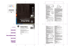
Appendix C
1500 Series Operating Instructions
Refer to the 1500 Series Installation Manual for more information
Normal Standby Condition
Trouble Condition
• Green “AX POWER” LED “ON”
• Yellow system trouble LED is “ON”
• All other LEDs “OFF”
• Yellow diagnostic LED is “ON”
• All switches in “NORMAL” position
• Integral sounder sounds a slow intermittent signal
Alarm Condition
• System trouble relay contacts transfer
• Red local zone alarm LED “ON”
Sounder Silence Switch Operated
• Integral sounder sounds a steady signal
• Integral sounder is “OFF” when system trouble is present
• Auxiliary alarm relay contacts transfer and latch
• Integral sounder is “ON” when system is in normal standyby
condition
• Supervised remote annunciator indication is “ON”
• Indicating circuits turn “ON”
Alarm Disconnect Switch Operated (Prior to Alarm
Condition) For Maintenance Use Only
• Disconnects local zone alarm from the auxiliary alarm relay
• Disconnects local zone alarm from the alarm indicating
cirucits
• System trouble relay contacts are not affected
• Will not silence supervisory alarm, supervisory trouble, or
system alarm signals
Supervisory Alarm Signal
• Integral sounder sounds a fast intermittent signal
• Zone #2 red local zone alarm LED is “ON”
• Red local zone alarm LED turns “ON”
• Zone #2 supervised remote annunciator indication is “ON”
• Supervised remote annunciator indication is “ON”
• Auxiliary alarm relay contact do not transfer
• Alarm signal from any other zone is not affected
• Indicating circuits are not activated
Alarm Disconnect Switch Operated (After Alarm
Condition) For Maintenance Use Only
• Yellow supervisory LED is “ON”
• Auxiliary alarm relay contacts remain latched
• Indicating sounder sounds a fast intermittent signal
• Alarm indicating circuits are turned “OFF”
• Zone #2 yellow local zone trouble LED is “ON”
• Red local zone alarm LED remains “ON”
• System trouble relay contacts transfer
• Supervised remote annunciator indication remains “ON”
• Yellow supervisory LED is “ON”
• Alarm signal from any other zone is not affected
Remote Test (Fire Drill)
Reset Switch Operated
• Indicating circuits turn “ON”
• Initiating circuit power removed (smoke detectors reset)
• Integral sounder sounds a slow intermittent signal
• Indicating circuits turn “OFF”
• Auxiliary alarm relay contacts do not transfer
• Integral sounder sounds steady signal
• LEM module does not transmit
• Auxiliary alarm relay is reset
• Keying the test switch will pulse the indicating circuits
Supervisory Trouble Signal
Reset Switch Released
• System restored to normal unless initiating devices are not
reset
Testing - Disconnect the AC power source during testing. If, after testing, a low battery condition exists, replace the
batteries.
“This equipment should be installed in accordance with the National Fire Protection Association’s Standard 72 (NFPA,
Batterymarch park, Quincy, MA 02269). Printed information describing proper installation, operation, testing, maintenance,
evacuation planning, and repair service is to be provided with this equipment.”
Warning:
Owner’s instruction notices: “Not to be removed by anyone except occupant.’
For Service Contact:
_________________________________________________________________________________________________________
_________________________________________________________________________________________________________
_________________________________________________________________________________________________________
________________________________________________________________________________________________________
GE Interlogix 12345 SW Leveton Dr., Tualatin, OR 97062
Sales: 800.547.2556
Technical Support: 800.648.7424
Remove this page, frame, and mount adjacent to control unit.
ESL 1500 Series Fire Alarm Control Panel
21