1
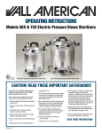
OPERATING INSTRUCTIONS
Non-Electric Pressure Steam Sterilizers
Models 1915X, 1925X, 1941X
1915X
Gross Volume 15.5 qt.
14.75 liter
1925X
Gross Volume 25 qt.
24 liter
1941X
Gross Volume 41.5 qt
39.5 liter
CAUTION! READ THESE IMPORTANT SAFEGUARDS!
FAILURE TO FOLLOW INSTRUCTIONS AND/OR
IMPROPER USE MAY RESULT IN SCALDING,
BODILY INJURIES OR EXPLOSION.
When using the pressure steam sterilizer,
basic safety precautions should always be
followed:
1. Read and understand instruction manual
before operating unit.
2. Do not touch hot surfaces. Use handles and
pot holders.
3. Close supervision is necessary when the
sterilizer is used near children.
6. Always check the pressure release devices
for clogging before use.
7. This sterilizer operates under pressure.
Improper use may result in scalding injury.
Make certain unit is properly closed before
operating. Read Operating Instructions.
8. Never loosen wing nuts until the steam
pressure gauge registers zero and you have
allowed any remaining pressure to escape
by opening the control valve (lever in the
vertical position).
4. Extreme caution must be used when
moving a sterilizer containing hot liquids.
9. Do not open the sterilizer until the unit has
cooled and internal pressure has been
reduced. Gauge should read zero at the
time. Read Operating Instructions.
5. Do not use the sterilizer for other than
intended use.
10.Never use the sterilizer for cooking or
processing food.
05/09-5M
11. Do not use this sterilizer with oil.
12. Do not subject your sterilizer to sudden
extreme temperature changes, as this will
cause expansion or contraction which can
crack a cast aluminum utensil. Do not move
a sterilizer from a cold storage area directly
onto a hot flame or element. Do not add
cold water to a sterilizer which has boiled
dry and is still hot. Do not cool the sterilizer
suddenly by pouring cold water on it or
wrapping cold wet towels around it.
13. As in all clinical laboratory settings, wear
safety glasses when attending to your
sterilizer.
SAVE THESE INSTRUCTIONS
Operating Instructions for Non-Electric Pressure Steam Sterilizers
IMPORTANT: DO NOT OPE RAT E T HIS PRE S S URE S T E AM
S TE RILIZE R UNT IL YOU HAVE T HOROUGHLY RE AD T HE S E
OPERAT ING INS TRUCTIONS .
CLEANING
When you are done using your sterilizer, you
need to empty the water from the unit, rinse
thoroughly and dry completely. This
procedure needs to be done daily. Do not
leave water in the unit overnight. Rinse
thoroughly between water changes. Store
your sterilizer in a dry area. On your next
use, fill the sterilizer with clean distilled
water. Distilled water is the recommended
water. If distilled water is not available, then
you may use your local water. If your local
water supply contains lime or high levels of
minerals, the unit will require periodic
cleaning to remove and prevent the buildup
of deposits.
Overpressure Plug
#1010
Geared Steam Gauge
# 72S
Control Valve
#65
Index Alignment Arrow
Units should be cleaned whenever there is a
buildup of lime or mineral deposits. After
many cycles, a white deposit may begin to
form on the bottom of the sterilizer. We
recommend cleaning with a lime remover.
Manufacturers of coffee makers have
cleaning solutions which may be used.
There are also solutions available at your
local hardware and drug stores that can be
used to clean aluminum. Follow the
manufacturer's instructions and make up a
solution of the cleaner, filling your sterilizer
above the standard operating level. Let the
sterilizer stand a few minutes then rinse
thoroughly. You may have to repeat this
procedure a few times to fully remove the
lime and mineral deposits from your
sterilizer.
Excess Pressure Relief Valve
#2050CS
Air Exhaust Tube
#2155
1941X Cover Shown
(1925X and 1915X similar)
You may also use standard white vinegar to
clean your sterilizer. Fill your sterilizer above
the standard operating level with vinegar and
let it stand a few minutes then rinse
thoroughly. You may have to repeat this
procedure a few times to fully remove the
lime and mineral deposits from your
sterilizer.
Never heat the sterilizer when filled
with a cleaning solution.
1
Elevation above sea level.
At altitudes greater than sea level, settings need
to be adequately adjusted to compensate for the
effect of altitude on the boiling point of water. We
suggest you increase pressure by 0.5psi for
every 1000 ft. of elevation above sea level.
City Altitude
Sea level
2000 ft
4000 ft
6000 ft
8000 ft
10,000 ft
Steam Pressure Required
15-17 psi
16-18 psi
17-19 psi
18-20 psi
19-21 psi
20-22 psi
Excess Pressure Relief Valve
#2050CS
Overpressure Plug
#1010
Control Valve
#65
Geared Steam Gauge
# 72S
Air Exhaust Tube
#2155-41
Aluminum Inner Container
#2164
Side Handle
#405
Rack
#151
Model 1941X shown
Figure A
2
Excess Pressure Relief Valve
#2050CS
Overpressure Plug
#1010
Geared Steam Gauge
# 72S
Control Valve
#65
Air Exhaust Tube
#2155-25 for 1925X
#2155-15 for 1915X
Aluminum Inner Container
#2162 for 1925X
#2163 for 1915X
Rack
#111
Figure B
3
Model 1925X shown
(1915X similar)
Lever vertical
or open
OPERATION
Metal-to-metal seal
Apply lubricant here
Fig. 1
1. LUBRICATE METAL-TO-METAL
SEAL. Apply lubrication to the point or
edge where side wall and bevel meet on
the inside of bottom (See Fig. 1 where
arrow tip is pointing). The bevel is not the
seat; only the point or edge where bevel
meets the wall. We recommend using a
high temperature lubricant such as a high
vacuum grease. Only a thin film is
required. Excess amounts may cause
leakage or gumming. Most scientific
supply houses have sterilizer lubricant.
There are many brands available. As a
substitute, you may also use petroleum
jelly or mineral oil.
2. Remove the cover from sterilizer by
loosening the bakelite wing nuts in a
counter-clockwise motion. Always undo
two opposite wing nuts at a time. Next,
remove inner container from the sterilizer.
(see Figure A, page 2) Pour clean water
(distilled is preferred) into the sterilizer
bottom (large outer pot) to a depth of not
less than 3⁄ 4 of an inch nor more than 1
inch. Place inner container rack (see
Figure A, page 2) into the bottom of the
container (see Figure A, page 2) with the
lip or edge side downward. The purpose
of the inner container rack is to provide an
air space in the bottom of the container so
that air may circulate freely. Place articles
to be sterilized inside the container. (Be
sure to arrange items so that the free
circulation of steam can occur during
sterilization.) You may wish to place a
towel or cloth on top of the items in the
container to absorb any moisture which
may drip down from the cover. Then place
packed container into the sterilizer. Make
certain that the air exhaust tube channel
(located on the inside of the container) is
in position on the right side of the
container when it is placed in the unit.
This is necessary so that when the cover
is placed on the unit you can guide the air
exhaust tube (Part No. 2155) (see Figure
A, page 2) into the channel.
3. Place sterilizer cover on unit,
making sure that the index
alignment arrow on the cover aligns
with index line/arrow on side of
bottom. Make certain when placing the
cover on the unit that the flexible tube is
inserted into the guide channel on the
inside wall of the aluminum container. It is
helpful to place the container in the unit
with the guide channel on the right hand
side as you face the unit. Tighten the wing
nuts on the cover evenly, always tightening down two opposite wing nuts at one
time. This will draw the cover down evenly
and assure a proper seal. NEVER USE A
WRENCH OR ANY MECHANICAL DEVICE
TO TIGHTEN WING NUTS. NEVER
HAMMER OR STRIKE THE WING NUTS
OR COVER WHILE OPENING OR
CLOSING.
4. Place unit on heat source. If the water you
have placed in the unit is cold, it will
require approximately 35 minutes before
steam begins escaping from the control
valve. Since it requires more time to bring
cold water up to operating temperature
than it takes warm or hot water, you can
reduce this time factor by:
Lever horizontal
or closed
steam escape
holes
valve body
Open control
valve
Closed control
valve
Fig. 2
Fig. 3
In both cases, observe the proper water
level.
5. Open CONTROL VALVE (See Fig. 2) by
placing valve lever in an upright position.
The steam generated at the bottom of the
sterilizer will travel around the outside of
the container and then down through the
material in the container to the bottom and
force the air from the bottom of container
up through the flexible air exhaust tube
and out of the control valve. It is
important that the steam be
permitted to escape vigorously from
the unit for at least seven minutes,
or until you see a continuous flow of
steam, and then you may close the
control valve. This process of
permitting the steam to escape is called
EXHAUSTING and is necessary to remove
the air trapped in the unit. The greatest
cause of sterilization failure is the
trapping of air in the material being
sterilized. Trapped air cannot
escape. It is imperative that all
trapped air be exhausted. With the
control valve in the closed position (See
Fig. 3), pressure will rise inside the
sterilizer and will be indicated on the
pressure gauge. When pressure gauge
reaches 17-19 pounds, reduce heat as
necessary to maintain constant pressure
of 17-19 pounds within the unit.
A. Pouring in hot water in place of cold, or
B. Pouring in cold water and then turning
on the heat source so that the water is
getting warmed prior to your beginning the
sterilization procedure
4
6. STERILIZATION PERIOD. The sterilization
period begins when the pressure steam
gauge needle registers in the green sterilization band shown on the face of the
gauge. The sterilization pressure range is
17-21 PSI. AT THIS TIME YOU BEGIN
THE TIMING OF THE STERILIZATION
CYCLE AND CONTINUE TIMING FOR
NOT LESS THAN 35 MINUTES.
7. At the end of the sterilization period, turn
off the heat source and move the lever on
the control valve to an upright (vertical)
position so that the steam is permitted to
escape. When the lever is in an upright
position, the steam will escape at
maximum. To avoid touching the hot
lever, you may use any object such as a
pencil or hot pad, etc., to move the lever
from the closed to open (vertical)
position. When the pressure gauge
indicates zero, loosen the wing nuts
evenly by turning two opposite wing nuts
counter-clockwise at one time. The wing
nuts, side handles and top handle will be
hot. Always use hot pads when handling.
Having removed all wing nuts from the
slots in the cover, you may lift the cover
slightly and turn the cover counterclockwise for easy removal. When
removing the cover, always tilt and
angle the cover away from yourself
or any other people in the area to
prevent injury from the hot steam.
In the event your cover sticks, use a large
standard screwdriver to pry the top loose.
Place the end of the screwdriver at an
angle between the cover and bottom near
a wing nut assembly. Do not go straight
in with the screwdriver or you will
damage the metal-to-metal seal. Gently
pry upward using the screwdriver as a
lever. Continue to pry upward at each
wing nut assembly area uniformly so that
the cover is raised evenly. In most cases,
the cover should come off rather quickly.
If you need further assistance, please
read metal-to-metal seal maintenance
instructions on this page.
The inner container may then be removed
from sterilizer for unloading. Use hot
pads when removing.
To start another sterilization cycle, repeat
procedure as outlined.
If the sterilizer is not going to be used
again, before putting the unit away, all
water should be emptied from the unit
and the unit be thoroughly dried inside. It
is recommended that the water be poured
out of the unit while the bottom is still
warm. The heat will help dry the unit if
you leave the cover off for 15 minutes
before placing the cover on the unit for
storage. For storage purposes, it is only
necessary to slightly tighten the wing
nuts enough to hold the cover on the
bottom. When storing, it is recommended
that the control valve be left in a vertical
Metal-to-metal seal
Apply lubricant here
Fig. 1
position to permit air to circulate into the
bottom.
metal seal must not be permitted to
become dry. It is also important to wipe
off the metal-to-metal seal by using a
clean towel to remove any build-up of
foreign material or particles trapped in
the lubricant. To remove any build-up of
hardened
lubricant on
the seal, use
0000 grade
steel wool in
a circular
motion
around the
Fig. 4
metal-toPressure Gauge
metal seal.
2. PRESSURE GAUGE, PART NO. 72S. (See
Fig. 4) Do not immerse the pressure
gauge in water when cleaning the unit.
The pressure gauge normally does not
require any maintenance except to make
certain the opening into the gauge on the
underside of the cover is open and free of
any foreign matter. If the gauge is ever
dropped, the unit should not be used
until the gauge has been checked to
Lever vertical
or open
Lever horizontal
or closed
MAINTENANCE:
1. METAL-TO-METAL SEAL. (See Fig. 1)
Periodically check your seal. The metalto-metal seal must be lubricated periodically (as stated in the instructions) to
prevent the cover from sticking to the
bottom because of dryness or lack of
lubrication. If the sterilizer is operated
without any lubricant, this could result in
severe damage to the metal-to-metal seal
and make it very difficult to remove the
cover in some cases, and also become
very difficult to maintain a steam-tight
seal. It is recommended that a small
amount of high temperature lubricant,
such as high vacuum grease, be applied
every third or fourth use. The metal-to5
steam escape
holes
valve body
Open control
valve
Closed control
valve
Fig. 2
Fig. 3
make sure that it is functioning properly.
If your gauge needs to be checked, take it
to a local scientific supply house.
3.CONTROL VALVE, PART NO. 65. (See
Fig. 2 & 3) To ensure long life and proper
operation of the control valve, periodic
cleaning is recommended. To clean,
unscrew the "knurled top" portion and
clean thoroughly in hot soapy water. If
any foreign material has built up inside
the unit, clean the ball and seat using a
solvent such as acetone or a similar
product. Be sure to clean the control valve
in hot soapy water once again after using
any solvent.
In the event that you are unable to
properly clean any buildup of foreign
material in your control valve, then it is
recommended that the control valve be
Fig. 5
discarded and replaced with a new
control valve.
4. AIR EXHAUST TUBE, PART NO. 2155.
(See Fig. 5) It is essential that the air
exhaust tube be frequently checked to
make sure that air passes freely through
it. We recommend that you blow air
through the air exhaust tube at least once
a month to make certain it is not blocked
or plugged with any foreign material. The
air exhaust tube is not part of the control
valve and can be removed separately
from the cover in the event that it is
blocked. Clean out the air exhaust tube
by using a small diameter wire, running
it through the entire length of the tube
several times. If you notice a buildup of
any foreign material on the inside of the
air passage or a buildup of any corrosion
on the inside of the air passage, then it is
recommended that you discard this tube
and replace it with a new air exhaust
tube.
5. EXCESS PRESSURE RELIEF VALVE,
PART NO. 2050CS. (See Fig. 6) This
sterilizer is equipped with a new type of
excess pressure relief valve. It is
designed for
longer, mainteDeflector Cap
nance-free
service;
however, we do
recommend that
the valve be
replaced every
three years in
normal service.
Fig. 6 Part No.
The valve is
2050CS Excess
designed to
Pressure Relief Valve
release pressure
at 26 PSI (plus/minus 1 PSI). Each valve
is equipped with a deflector cap which
will direct any steam released in a
downward direction. Also it is possible to
manually release steam and pressure in
this unit by simply grasping the deflector
cap and pulling upwards slightly. The
deflector cap will be hot. Always use hot
pads when handling. This will instantly
release pressure inside the unit until you
release the cap and the valve, at which
time the valve instantly reseals, thereby
stopping any further pressure from
escaping.
6. OVERPRESSURE PLUG, PART NO. 1010.
This ALL-AMERICAN Sterilizer is
equipped with an additional safety device
which is the Overpressure Plug, Part No.
1010. The purpose of the overpressure
plug is to offer an extra margin of safety
whenever the sterilizer is used. The
overpressure plug is designed to release
pressure in the range of 30 to 50 PSI.
The overpressure plug is made from
silicone and is red in color and is found
on the top surface of the sterilizer cover,
located directly to the rear of the top
handle, in front of Part No. 2050CS
Excess Pressure Relief Valve. See Figure
A (page 2) and Figure 7.
For the most efficient results and best
possible performance, it is recommended
6
that you replace the overpressure plug
every 6 months. It should always be
replaced whenever it becomes hard or
deformed.
At least every month during period of
use, the opening in the cover where the
overpressure plug fits should be checked
to determine that no foreign material,
residue, or buildup of grease is present,
and the opening be cleaned with hot
soapy water (a toothbrush is helpful) to
maintain a clean opening. This
cleaning/inspection is in addition, of
course, to normal daily cleaning
performed after using the unit.
The overpressure plug can be removed
for cleaning using fingers to pull it out of
its opening from the underside of the
cover. Before you re-install the
overpressure plug, check the opening in
the cover to be sure that it is absolutely
free of any foreign material or
grease/residue buildup. After cleaning,
reinsert the overpressure plug by pushing
the round top side into the opening from
the underside of the cover. When the
overpressure plug is correctly in position,
the indented portion will be visible from
Part No. 1010
Overpressure Plug
Top of Plug is rounded
Top Lip
Under side of plug is
indented
Cover top side
Fig. 7
the underside of the cover. Be certain to
check after inserting plug that the round
top of plug and top lip are fully thru the
opening and that the top lip is not folded
under. See Figure 7.
How Part No. 2050CS
Works
Closed
Resilient seal design prevents leakage.
Sealing efficiency increases with
increased pressure up to cracking
pressure. Metal-to-metal seat on low
pressure side supports spring load,
prevents sticking.
Open
When system pressure overcomes spring
force, poppet opens, momentarily
exposing variable orifice between poppet
and body to pass increasing flow with
minimum pressure rise without
blowdown.
Resealing
Resilient seal automatically establishes
line of contact with spherical seat. Seal
provides dead tight reseal very close to
cracking pressure.
IMPORTANT STERILIZATION FACTS
Steam is an ideal sterilizing
agent since it kills microbes
quickly, and steam has the
additional important property of
self-caused forced penetration.
A large volume of steam
condenses to a very small
volume of water and more
steam is drawn in to replace it.
This causes excellent
penetration of fabrics and some
papers and plastic films. Hot
air or sterilizing gases do not
approach steam in their ability
to penetrate.
The greatest cause of sterilization failure is the trapping of
air in the material being
sterilized so that it cannot
escape. When this happens, the
air forms a cool air pocket
which has a lower temperature
than the surrounding steam. It
can also form an air-steam
mixture which has a lower
temperature than the pure
steam. The most frequent
causes for this failure are
dressing packs wrapped too
tightly, made too large, failure
to turn basins and other metal
or glass containers onto their
sides, and failure to properly
follow the directions as to
current sterilizer operation and
maintenance. (Refer to Item 5,
page 4, regarding "exhausting"
to remove trapped air.)
Operating characteristics of the No.
2050CS excess pressure relief valve are:
A. Zero leakage to 95-98% of cracking
pressure.
B. Increased sealing efficiency as
pressure increases. Resilient "Q" ring
seal is forced against metal seat as
pressure increases up to set cracking
pressure.
C. Cracking pressure accuracy. Valves
are preset to required cracking
pressure of 26 PSI.
7
It is essential that all sterilizers
be regularly checked for proper
steam penetration to the center
of the load. Since the first sign
of sterilization failure is a drop
in the temperature at the center
of the dressing pack or
sterilizer load, it is recommended that a temperature
measuring device be used at
the center of each pack or load
of instruments. Indicating tape
or strips are no substitute for
the self-contained types
as…"melt indicator inside a
small glass vial," as temperature accuracy is essential. The
pressure gauge on the sterilizer
indicates the approximate
temperature at the exhaust line,
not at the center of the packs.
The gauge cannot indicate the
presence of trapped air,
therefore, center-of-pack
controls or vials are recommended. Different types and
brands of sterilization
indicators are available from
your hospital supply or scientific supply dealer.
PRESSURE GAUGE
ACCURACY: The gauges are
rated as having an accuracy of
3%-2%-3%. This designates
plus or minus 3% of the full
span for the first and last
quarter of the dial, and 2% for
the middle 50% of the dial.
More specifically, this gauge
rating comes from the pressure
gauge standard ANSI B40-11980. This standard is entitled
"Gauges-Pressure, Indicating
Dial Type-Elastic Element," and
covers every aspect of pressure
gauge manufacture and use.
The gauge is considered
"Accuracy Grade B" in accordance with this specification.
SOLUTIONS/SUGGESTIONS
FOR WET BAGS OR PACKS
IN STERILIZER:
1. Place absorbent towels
between layers and on top of
items being sterilized.
2. Use sterile gloves to remove
the sterile bags or packs from
container.
3. Use sterile tongs to remove
sterile bags or packs from
container.
RETURN/SERVICE
Should the pressure sterilizer ever be dropped, the unit must be examined to determine if any damage has occurred. We recommend the
unit be returned to our factory to be thoroughly checked inside and out for any damage. Prior to return to the factory, all sterilizers must
be cleaned to remove any biological material or contaminants. We will examine the entire unit, including the control valve and gauge,
and determine if the unit has sustained damage, and notify you of our findings.
A Return Authorization (RA) Number is required by our company to return any product manufactured by Wisconsin Aluminum Foundry.
Merchandise returned without an RA Number will be refused. To obtain an RA Number contact our company by either writing, faxing or
calling our Customer Service Department at 920-682-8627. All defective merchandise must be returned to our factory before credit or a
replacement will be issued; do not destroy the defective merchandise. Any products returned must include paperwork stating the reason
for the return, when and where the item(s) were purchased, model numbers, quantities, etc., and who to contact with any questions.
Should you have any questions at all about the operation of your ALL-AMERICAN Pressure Sterilizer, please write the Consumer
Products Division, and we will promptly answer your questions.
To order any replacement parts, please refer to the parts price list. If you do not have a copy of our current parts price list, you may write
the company and one will be forwarded to you by return mail.
ALL-AMERICAN PRESSURE STEAM STERILIZER LIMITED WARRANTY
This quality sterilizer is designed and manufactured to provide many years of satisfactory performance under normal use. Wisconsin Aluminum
Foundry pledges to the original owner that should there be any defects in material or workmanship during the first year after purchase, we will
repair or replace it at our option. This pledge does not apply to damage caused by shipping. To obtain service under the warranty:
1. A Return Authorization (RA) Number is required by our company to return any product manufactured by Wisconsin Aluminum Foundry.
Merchandise returned without an RA Number will be refused. To obtain an RA Number contact our company by either writing, faxing or calling
our Customer Service Department at 920-682-8627. All defective merchandise must be returned to our factory before credit or a replacement
will be issued; do not destroy the defective merchandise. Any products returned must include paperwork stating the reason for the return,
when and where the item(s) were purchased, model numbers, quantities, etc., and who to contact with any questions. Prior to return to the
factory, all sterilizers must be cleaned to remove any biological material or contaminants.
2. Return sterilizer, shipping prepaid, direct to:
Wisconsin Aluminum Foundry Co., Inc.
Consumer Products Division
1931 South 14th Street
Manitowoc, WI 54220
IMPORTANT — PLEASE READ
Any alterations, modifications or changes of any type made to the sterilizer or to any component thereof will void this warranty!
We want you to obtain maximum performance from using this quality sterilizer and we ask that you take the time to read and follow the operating
instructions. Failure to follow instructions, damage caused by improper replacement parts, abuse, or misuse will void this pledge. This warranty
gives you specific legal rights, and you may also have other rights which vary from state to state. This is Wisconsin Aluminum Foundry's
personal pledge to you and is being made in place of all other express warranties.
8
ALL-AMERICAN PRESSURE STEAM STERILIZERS PARTS LIST
Part No.
Description
54
Clamp bolt
55
Pin for clamp bolt
64
Bakelite wing nut
65
Control valve
72S
Geared steam gauge
73
Lens for steam gauge (replacement)
76
Bakelite top handle
77
Bakelite top handle screw
78
Retaining bayonet clamp
79
Retaining bayonet clamp screw
111
Rack for inside aluminum container, fits 1915X, 1925X
151
Rack for inside aluminum container, fits 1941X
405
Side handle, complete for 1941X
1010
Overpressure plug for sterilizer, red color
2050CS
Excess pressure relief valve
2155-15
Air exhaust tube for 1915X
2155-25
Air exhaust tube for 1925X
2155-41
Air exhaust tube for 1941X
2162
Aluminum container for 1925X
2163
Aluminum container for 1915X
2164
Aluminum container for 1941X
*6054
Thermometer, stainless steel, dual scale, C scale 10-150°; F scale 50-300°
*There is a factory installation fee for the thermometer. We recommend that the thermometer be installed at the factory.
NO GUARANTEE OR RESPONSIBILITY FOR THE PROPER FUNCTIONING OF THIS PART CAN BE
ASSUMED BY THE COMPANY IF IT IS NOT INSTALLED AT THE FACTORY.
9
SPECIFICATIONS
Model 1915X (15 qt/14 liter)
Model 1925X (25 qt/24 liter)
Model 1941X (41 qt/39 liter)
Gross Capacity
Overall Height
Bottom Height
Inside Diameter
Unit Weight
Inner Container No. 2163
Inside Depth
Inside Diameter
Circumference
Capacity
Volume
Carton Dimensions
Gross Capacity
Overall Height
Bottom Height
Inside Diameter
Unit Weight
Inner Container No. 2162
Inside Depth
Inside Diameter
Circumference
Capacity
Volume
Carton Dimensions
Gross Capacity
Overall Height
Bottom Height
Inside Diameter
Unit Weight
Inner Container No. 2164
Inside Depth
Inside Diameter
Circumference
Capacity
Volume
Carton Dimensions
Shipping Weight
Unit Pack: 1
15 qt/14 liter
121 ⁄4 " / 31.2cm
73 ⁄4 " / 19.7cm
125⁄8 " / 32.1cm
15 lbs. / 6.8 kg.
53 ⁄4 " / 14.6cm
111 ⁄8 " / 28.3cm
357⁄8" / 91.1cm
9.5 qt/9 liter
550in3/9029cm3
151 ⁄2 " x 141 ⁄2 " x 131 ⁄2 "
39.4cm x 36.8cm x 34.3cm
21 lb. / 9.52kg.
Cube: 1.76
25 qt/24 liter
163⁄4 " / 42.5cm
121⁄4 " / 31.2cm
125⁄8 " / 32.1cm
181⁄4 lbs. / 8.3kg
101⁄4 " / 26cm
111 ⁄8 " / 28.3cm
357⁄8" / 91.1cm
17.6 qt/16.6 liter
1016in3/16,655cm3
151 ⁄2 " x 141 ⁄2 " x 181 ⁄2 "
39.4cm x 36.8cm x 47cm
25 lb. / 11.34kg.
Cube: 2.41
Shipping Weight
Unit Pack: 1
Shipping Weight
Unit Pack: 1
41 qt/39 liter
19" / 48.3cm
141⁄4 " / 36.2cm
151 ⁄4 " / 38.7cm
33 lbs. / 15kg.
101⁄2 " / 26.7cm
14" / 35.6cm
441⁄2" / 113cm
27.9 qt/26.4 liter
1613in3/26,451cm3
19" x 19" x 201⁄2 "
48.3cm x 48.3cm x 52.1cm
43 lb. / 19.5kg.
Cube: 4.28
ELECTRIC MODELS ARE ALSO AVAILABLE
Model 25X (25 qt/24 liter)
Model 50X (25 qt/24 liter)
Model 75X (41 qt/39 liter)
Model 25X-120: 120 Volt, 50/60 Hz
Model 25X-240: 240 Volt, 50/60 Hz
Gross Capacity
Overall Height
Bottom Height
Inside Diameter
Unit Weight
Inner Container No. 2156
Height
Diameter
Circumference
Capacity
Volume
Carton Dimensions
Model 50X-120: 120 Volt, 50/60 Hz
Model 50X-240: 240 Volt, 50/60 Hz
Gross Capacity
Overall Height
Bottom Height
Inside Diameter
Unit Weight
Inner Container No. 2156
Height
Diameter
Circumference
Capacity
Volume
Carton Dimensions
Model 75X-120: 120 Volt, 50/60 Hz
Model 75X-240: 240 Volt, 50/60 Hz
Gross Capacity
Overall Height
Bottom Height
Inside Diameter
Unit Weight
Inner Container No. 4156
Height
Diameter
Circumference
Capacity
Volume
Carton Dimensions
1050 watts/8.75 amps
1050 watts/4.38 amps
25 qt / 24 liter
163 ⁄ 4 " / 42.5cm
121 ⁄ 4 " / 31.2cm
125 ⁄ 8 " / 32.1cm
26 lbs. / 11.8kg.
81 ⁄ 2 " / 21.6cm
111 ⁄ 8 " / 28.3cm
357⁄8" / 91.1cm
14.5 qt / 13.7 liter
835in3 / 13,688cm3
21" x 171 ⁄ 2 " x 181 ⁄ 2 "
56.5cm x 44.5cm x 48.3cm
Shipping Weight
31 lb. / 14.06kg.
Unit Pack: 1
Cube: 3.93
Optional No. 2180 Support Base 2" / 5cm high
Outside Diameter
123 ⁄ 4 " / 32.4cm
Inside Diameter
123 ⁄ 8 " / 31.4cm
Elevates Sterilizer Above Surface 13 ⁄ 8 " / 3.5cm
1650 watts/13.75 amps
1650 watts/6.88 amps
25 qt / 24 liter
163 ⁄ 4 " / 42.5cm
121 ⁄ 4 " / 31.2cm
125 ⁄ 8 " / 32.1cm
29 lbs. / 13.2kg.
81 ⁄ 2 " / 21.6cm
111 ⁄ 8 " / 28.3cm
357⁄8" / 91.1cm
14.5 qt / 13.7 liter
835in3 / 13,688cm3
21" x 171 ⁄ 2 " x 181 ⁄ 2 "
56.5cm x 44.5cm x 48.3cm
Shipping Weight
34 lb./15.4kg.
Unit Pack: 1
Cube: 3.93
Optional No. 2180 Support Base 2" / 5cm high
Outside Diameter
123 ⁄ 4 " / 32.4cm
Inside Diameter
123 ⁄ 8 " / 31.4cm
Elevates Sterilizer Above Surface 13 ⁄ 8 " / 3.5cm
10
1650 watts/13.75 amps
1650 watts/6.88 amps
41 qt / 39 liter
19" / 48.3cm
141 ⁄ 4 " / 36.2cm
151 ⁄ 4 " / 38.7cm
45 lbs. / 20.4kg.
101 ⁄ 4 " / 26cm
14" / 35.6cm
441⁄2" / 113cm
27.3 qt / 25.8 liter
1578in3 / 25,856cm3
24" x 24" x 21"
61cm x 61cm x 53.3cm
Shipping Weight
51 lb. / 23.1kg.
Unit Pack: 1
Cube: 7
Optional No. 4180 Support Base 3" / 7.6cm high
Outside Diameter
161 ⁄ 4 " / 41.3cm
Inside Diameter
15" / 38.1cm
Elevates Sterilizer Above Surface 21 ⁄ 4 " / 5.7cm
WISCONSIN ALUMINUM FOUNDRY CO., INC.
CORRESPONDENCE:
WISCONSIN ALUMINUM FOUNDRY CO., INC.
P.O. BOX 246
MANITOWOC, WISCONSIN 54221-0246
PHONE: (920) 682-8627
FAX: (920) 682-4090
web page: store.wafco.com
email: [email protected]
RETURN & SERVICE:
WISCONSIN ALUMINUM FOUNDRY CO., INC.
CONSUMER PRODUCTS DIVISION
1931 SOUTH 14TH STREET
MANITOWOC, WI 54220
INSTRUCCIONES DE OPERACIÓN
Esterilizadores No Eléctricos de Vapor a Presión
Modelos 1915X, 1925X, 1941X
1915X
Volumen bruto 15.5 cuartos / 14.75 litros
1925X
Volumen bruto 25 cuartos / 24 litros
1941X
Volumen bruto 41.5 cuartos / 39.5 litros
¡CUIDADO! ¡LEA ESTAS IMPORTANTES NORMAS DE SEGURIDAD!
SI FALLA EN SEGUIR LAS SIGUIENTES INSTRUCCIONES Y / O SI LAS USA INAPROPIADAMENTE
TAL VEZ RESULTE CON ESCALDADURAS, LESION
FÍSICA O UNA EXPLOSION.
Cuando este usando el esterilizador eléctrico de
vapor a presión, las precauciones básicas de
seguridad siempre deben de seguirse:
1. Lea y entienda el manual de instrucciones antes
de operar esta unidad.
2. No toque superficies calientes. Use agarraderas y
coge ollas.
3. Estricta supervisión es necesaria cuando el esterilizador es usado donde hay niños.
6. Antes de ser usados siempre revise los aparatos
de presión que no estén obstruidos.
7. Este esterilizador opera bajo presión. El uso
inapropiado puede resultar en lesión por
quemaduras. Antes de operar este seguro de
que la unidad esta perfectamente cerrada. Lea
las instrucciones de operación.
8. Nunca afloje las mariposas hasta que la presión
en el manómetro registre cero y ha permitido
que cualquier presión sobrante se ha dejado
escapar al abrir la válvula de control (palanca en
posición vertical).
4. Tenga extremo cuidado cuando este trasladando el
esterilizador con líquidos calientes.
9. No abra el esterilizador hasta que la unidad se
haya enfriado y la presión interna reducida. En
el manómetro se debe leer cero en este
momento. Lea las instrucciones de operación.
5. No use al esterilizador con otros fines de los ya
establecidos.
10. Nunca use el esterilizador para cocinar o
procesar comida.
11. No use este esterilizador con aceite.
12. No exponga el esterilizador a cambios de
temperaturas repentinas y extremadas, pues esto
puede causar la expansión o contracción lo cual
puede causar rajaduras en el utensillo de
aluminio fundido. No traslade el esterilizador de
una bodega fría directamente al calor de la llama
u otro elemento. No le adhiera agua fría al esterilizador que ha estado hirviendo, esta seco y
todavía esta caliente. No enfríe repentinamente el
esterilizador con agua fría o envolviéndolo en
toallas mojadas con agua fría.
13. Como en todos los laboratorios clínicos use
anteojos de seguridad cuando este operando su
esterilizador.
GUARDE ESTAS INSTRUCIONES.
Instrucciones de Operación para Esterilizadores No Eléctricos de Vapor a Presión
IMPORTANT E : NO OPERE E S T E ES T E RILIZADOR DE PRES ION
AL VAPOR HASTA QUE HAYA LE IDO T OTALME NT E E S TAS
INT RUSIONE S DE OPERACIÓN.
LIMPIANDO
Cuando ha terminado de usar el esterilizador, necesita sacarle el agua a la unidad,
enjuáguelo literalmente y séquelo completamente. Este procedimiento necesita hacerse
diariamente. Durante la noche no deje agua
en la unidad. Enjuáguelo literalmente entre
cambios de agua. Almacene el esterilizador
en una área seca. La próxima vez que use el
esterilizador llénelo con agua limpia
destilada. Agua destilada es el agua
recomendada. Si el agua destilada no es
accesible use el agua local. Si el agua del
acueducto local contiene cal o altos niveles
de minerales, la unidad requerirá ser
limpiada periódicamente para remover y
prevenir las acumulaciones de cal o
depósitos de minerales.
Las unidades deben de ser limpiadas
siempre que haya acumulaciones de cal o
minerales. Después de muchos ciclos, un
deposito blanco talvez se empiece a formar
en el fondo del esterilizador. Le recomendamos limpiar con un removedor de cal. Los
fabricantes de cafeteras tienen limpiadores
que talvez pueda usar. También hay
soluciones disponibles en su ferretería o
farmacias que se pueden usar para limpiar el
aluminio. Siga las instrucciones del fabricante y haga una solución de limpiador,
llenando el esterilizador mas arriba del nivel
normal de operación. Deje el esterilizador
por pocos minutos y después enjuáguelo
literalmente. Tal vez tenga que repetir este
procedimiento varias veces para remover
completamente la cal y depósitos de
minerales.
Tapón de
Sobrepresión #1010
Manómetro de vapor
#72S
Válvula de escape por exceso de
presión #2050CS
Válvula de control
#65
Flecha del índice de
alineación
Tubo de escape del aire
#2155
1941X muestra la tapa (1925X y 1915X similar)
Usted tal vez use vinagre blanco para limpiar
el esterilizador. Llene el esterilizador mas
arriba del limite normal de operación con
vinagre déjelo por pocos minutos y
enjuáguelo totalmente. Usted tal vez tenga
que repetir este procedimiento pocas veces
para remover completamente la cal y
minerales del esterilizador.
Elevación sobre el nivel del mar.
En altitudes sobre del nivel del mar, hay que
hacer ajustes para compensar adecuadamente el
punto en que hierve el agua debido a los efectos
de la altitud. Le sugerimos aumentar la presión a
0.5psi por cada 1000 pies de altitud sobre el
nivel del mar.
Altitud de la ciudad Presión del Vapor requerida
Al nivel del mar
2000 pies
4000 pies
6000 pies
8000 pies
10.000 pies
Nunca caliente el esterilizador
cuando esta lleno con soluciones
limpiadoras.
1
15 –17psi
16 – 18psi
17 – 19psi
18 – 20psi
19 – 21psi
20 – 22psi
Válvula de escape por exceso de
presión #2050CS
Tapón de
Sobrepresión #1010
Válvula de control
#65
Manómetro de vapor
#72S
Tubo de escape del aire
#2155-41
Mango lateral #405
Recipiente interno de
aluminio #2164
Parrilla #151
Figura A
2
Muestra el Modelo 1941X
Tapón de
Sobrepresión
#1010
Válvula de escape por exceso de presión
#2050CS
Manómetro de vapor
#72S
Válvula de control
#65
Tubo de escape del aire
#2155-25 para 1925X
#2155 – 15 para 1915X
Recipiente interno de
aluminio
#2162 para 1925X
#2163 para 1915X
Parrilla
#111
Figura B
3
Muestra el Modelo 1925X
(1915X similar)
Palanca vertical o abierta
Palanca horizontal
o cerrada
OPERACIÓN
Sello de metal a metal
Aplique lubricante aquí
Fig. 1
1. LUBRIQUE EL SELLO DE METAL-AMETAL. Lubrique el punto o borde
donde el lado de la pared y el bisel se
juntan por dentro en el fondo (Ver Fig. 1
donde la punta de la flecha esta
señalando). El bisel no es el asiento;
solamente el punto o borde donde el
bisel se encuentra con la pared. Le
recomendamos usar lubricante para alta
temperatura como la grasa para vacío
alto. Se requiere solamente una capa
delgada. Excesos de lubricantes pueden
causar escapes y ponerse pegajoso. El
lubricante para el esterilizador se puede
conseguir en almacenes de abastecimiento científico, hay muchas marcas
disponibles. Como substituto, usted puede
usar pomada de petroleo o aceite mineral.
2. Remueva la tapa del esterilizador
haciendo girar las mariposas de baquelita
en el sentido contrario a las manecillas
del reloj. Siempre afloje dos mariposas
opuestas a la vez. Enseguida, remueva el
recipiente interno del esterilizador (Ver
Fig. A, Pág. 2). Vierta agua limpia (preferiblemente agua destilada) en el fondo del
esterilizador (olla exterior grande) no
menos de 3⁄ 4" y no mas de 1 puldada.
Ponga la parrilla del recipiente interno
(ver la figura A pagina 2) en el fondo del
recipiente. (Ver Fig. A pagina 2) con el
labio o borde hacia abajo. El propósito de
esta parrilla dentro del recipiente es
proveer espacio de aire en el fondo del
recipiente de tal manera que el aire circule
libremente. Ponga los artículos que va a
esterilizar en el recipiente. (Este seguro de
arreglar los artículos de tal manera que el
vapor circule libremente durante la esterilización.) Talvez usted quiere poner una
toalla encima de los artículos en el recipiente para absorber cualquier humedad
que se chorree hacia abajo desde la tapa.
Entonces ponga un recipiente empacado
dentro del esterilizador. Este seguro que el
canal tubo del aire de escape (localizado
dentro del recipiente) esta en su posición
al lado derecho del recipiente cuando es
puesto en la unidad. Esto es necesario, así
que cuando la tapa esta puesta en la
unidad puede guiar el aire por el tubo de
aire de escape (parte No. 2155) (Ver Fig.
A, pagina 2) dentro del canal.
3. Ponga la tapa del esterilizador en
la unidad, este seguro que la flecha
de señal en la tapa esta alineada
con la línea de marca a un lado del
fondo. Este seguro que cuando pone la
tapa en la unidad el tubo flexible es
insertado en la guía del canal en la pared
interna del recipiente de aluminio. Es de
mucha ayuda el poner el recipiente en la
unidad con la guía del canal al lado
derecho cuando usted esta mirando la
unidad. Apriete parejo las mariposas en la
tapa, siempre apriete dos mariposas
opuestas a un tiempo. Esto aprieta la tapa
hacia abajo en una forma pareja y asegura
el sello apropiadamente. NUNCA USE
UNA LLAVE O CUALQUIER APARATO
MECANICO PARA APRETAR LAS
MARIPOSAS. NUNCA MARTILLE O
GOLPIE LAS MARIPOSAS O LA TAPA
MIENTRAS LA ESTA ABRIENDO O
CERRANDO.
4. Ponga la unidad en la fuente de calor. Si
el agua que vertió en la unidad esta fría,
requiere aproximadamente 35 minutos
antes de que el vapor empiece a escaparse
de la válvula de control. Como más
tiempo es requerido para calentar el agua
fría que el agua caliente hasta la temperatura de operación usted puede reducir
este tiempo al:
A. Verter agua caliente en vez de agua
fría, o
B. Verter agua fría y entonces prender la
unidad de tal manera el agua empieza a
calentar antes de empezar el procedimiento de esterilización.
En ambos casos observe el nivel
apropiado del agua.
4
Huecos de escape
de vapor
Armadura de la
Válvula
Válvula Control
abierto
Válvula control
cerrada
Fig. 2
Fig. 3
5. Abra LA VÁLVULA DE CONTROL (Ver Fig.
2) al poner la palanca de la válvula en la
posición hacia arriba a mano derecha. El
vapor generado en el fondo del esterilizador recorrerá alrededor por fuera del
recipiente y después hacia abajo a través
del material en el recipiente hasta el fondo
y forza el aire desde el fondo del recipiente hacia arriba a través del tubo flexible
del aire de escape y afuera de la válvula de
control. Es importante que el vapor
se deje escapar por lo menos por
siete minutos vigorosamente de la
unidad o hasta que vea un flujo
continuo de vapor y después cierre
la válvula de control. Este proceso de
permitir que el vapor se escape se
denomina ESCAPANDO y es necesario
remover el aire atrapado en la unidad. La
mayor causa de falla en el esterilizador es el aire atrapado en el
material que esta siendo esterilizado. El aire atrapado no se puede
escapar. Es imperativo que todo el aire
atrapado se deje escapar. Con la válvula
de control cerrada (Ver Fig. 3), la presión
aumentara dentro del esterilizador y será
indicado en el manómetro de presión.
Cuando el manómetro de presión alcanza
17-19 libras, reduzca el calor como sea
necesario para mantener una presión
constante de 17-19 lbs dentro de la
unidad.
6. PERIODO DE ESTERILIZACIÓN. Este
periodo empieza cuando la aguja del
manómetro del vapor a presión, se
registra en la banda verde de esterilización la cual se puede ver en la cara del
manómetro. La presión de esterilización
varia entre 17-21 PSI. EN ESTE
MOMENTO USTED COMIENZA A
CRONOMETRAR EL TIEMPO DEL CICLO
DE ESTERILIZACIÓN Y CONTINUA
CRONOMETRANDO POR NO MENOS DE
35 MINUTOS.
7. Al final del periodo de esterilización apague
la fuente de calor y mueva la palanca en el
control de la válvula hacia arriba en
posición (vertical) para que el vapor pueda
escaparse. Cuando la palanca esta en la
posición vertical, el vapor se escapa al
máximo. Para evitar tocar la palanca
caliente para mover la de la posición
(vertical) cerrado a abierto puede usar un
objeto como un lápiz o una almohadilla
para objetos calientes etc. Cuando la
presión en el manómetro indica cero, afloje
las mariposas por parejas girando de a dos
opuestas al mismo tiempo en sentido
contrario a las manecillas del reloj. Las
mariposas y los mangos laterales y el
mango de arriba estarán calientes. Siempre
use almohadillas para objetos calientes
cuando este operando el esterilizador.
Habiendo removido todas las mariposas de
las ranuras de la tapa levante un poco la
tapa y gire la tapa en sentido contrario a las
manecillas del reloj para zafarla fácilmente.
Cuando esta removiendo la tapa,
siempre incline y ponga en ángulo la
tapa lejos de usted u otras personas
en el área para evitar lesiones
producidas por el vapor caliente.
En caso de que la tapa se pegue, use un
destornillador de pala largo para hacer
palanca y aflojar la. Ponga la punta del
destornillador haciendo ángulo entre la
tapa y la parte baja del ensamble de la
mariposa. No vaya derecho con el
destornillador por que dañaría el
empaque de metal a metal. Suavemente
haga palanca hacia arriba Continúe levantando uniformemente usando el destornillador como palanca en cada uno del
ensamble de las mariposas de tal manera
que la tapa es levantada en una forma
uniforme. En la mayoría d e los casos la
tapa debe despegarse rápidamente. Si
usted necesita mas asistencia, por favor
lea la pagina de instrucciones de mantenimiento del empaque de metal a metal.
El recipiente interior tal vez sea removido
del esterilizador para desocuparlo. Use
almohadillas para objetos calientes
cuando lo remueve.
Para comenzar otro ciclo de esterilización,
repita el procedimiento como se indica:
Si el esterilizador no se va a usar otra
vez, antes de guardar la unidad, debe
sacar toda el agua y la unidad debe ser
secada por dentro. Se recomienda que el
agua sea vaciada de la unidad mientras
que esta caliente en el fondo, pues el
calor ayuda a secarla, deje usted la
unidad destapada por 15 minutos antes
de ponerle la tapa para guardarla. Con el
propósito de guárdala, es solamente
necesario apretar un poquito las
mariposas lo suficiente para sostener la
tapa en el fondo. Cuando la guarda es
recomendado que deje la válvula de
control en posición vertical para permitir
que el aire circule en el fondo.
MANTENIMIENTO:
Sello de metal a metal
Aplique lubricante aquí
2. MANÓMETRO DE PRESION, PARTE NO.
72S. (Ver Fig. 4) Cuando este limpiando
la unidad no sumerja el manómetro de
presión en agua. El manómetro de
presión normalmente no requiere ningún
mantenimiento
excepto el
estar seguro
de que la
abertura en el
manómetro
esta por
debajo de la
tapa y esta
Fig. 4
abierta y libre
Manómetro de vapor
de cualquier
materia
extraña. Si
alguna vez el manómetro se cae, la
unidad no debe ser usada hasta que el
manómetro haya sido revisado para estar
seguro de que esta funcionando apropiadamente. Si el manómetro necesita ser
examinado, llévelo a un almacén de
abastecimiento científico
Palanca vertical o abierta
Palanca horizontal
o cerrada
Fig. 1
1. METAL-A-METAL SELLO. (Ver Fig. 1)
Periódicamente revise el sello. El sello del
metal-a-metal debe ser lubricado
periódicamente (como se expresa en las
instrucciones) para prevenir que la tapa se
pegue en el fondo debido a la resequedad
o falta de lubricación. Si el esterilizador es
operado sin lubricante, esto puede
resultar en daño severo al sello del metala-metal y en algunos casos hacer muy
difícil el remover la tapa, y también se
vuelve muy difícil mantener el sello del
vapor apretado. Se recomienda una
pequeña cantidad de lubricante para altas
temperaturas, como la grasa para alto
vacío sea aplicada cada tercera o cuarta
vez que la usa. Al sello del metal-a-metal
no se le debe permitir que se seque. Es
también importante limpiar con una toalla
limpia el sello del metal-a-metal para
remover cualquier acumulación de
materiales extraños o partículas atrapadas
en el lubricante. Para remover cualquier
acumulación de lubricante endurecido en
el sello use un estropajo de 0000 grados
en forma circular alrededor del sello del
metal-a-metal.
5
Huecos de escape
de vapor
Armadura de la
Válvula
Válvula Control
abierto
Válvula control
cerrada
Fig. 2
Fig. 3
3. VALVULA DE CONTROL, PARTE No. 65.
(Ver Fig. 2 & 3) Para asegurar larga vida
y operación apropiada de la válvula de
control, es recomendado limpiarla
periódicamente. Para limpiar desatornille
una porción de la "tapa graficada" y
límpiela literalmente en agua jabón
caliente. Si algún material extraño se ha
acumulado dentro de la unidad, limpie la
bola y el asiento usando solvente como
la acetona o un producto similar. Este
seguro de limpiar la válvula de control en
agua jabón caliente una vez mas después
de usar cualquier solvente. En caso de
que no pueda limpiar cualquier acumu-
lación de material extraño en al válvula
de control, es recomendado que la
válvula sea descargada y reemplazada
con una nueva.
4. TUBO DEL AIRE DE ESCAPE,
PARTE NO. 2155.
Fig. 5
(Ver Fig. 5) Es esencial que el tubo del
aire de escape sea frecuentemente
revisado para estar seguro de que el aire
pasa libremente a través del tubo, le
recomendamos soplar aire a través del
tubo de escape por lo menos una vez al
mes para estar seguro de que no esta
bloqueado o atascado con materiales
extraños. El tubo del aire de escape no es
parte de la válvula de control y puede
zafarse de la tapa por separado en caso
de que este bloqueado. Limpie el tubo
usando un alambre de diámetro pequeño,
pasándolo varias veces a lo largo del
tubo. Si nota que hay acumulación de
material extraño dentro del pasaje de aire
o una acumulación de oxido se
recomienda reemplazar el tubo por uno
nuevo.
5. VALVE DE SEGURIDAD PARA EXCESO
DE PRESION, PARTE NO. 2050CS.
(Ver Fig. 6) Este esterilizador esta
equipado con un nuevo tipo de válvula
de seguridad para el exceso de presión.
Esta diseñado para durar largo tiempo
libre de mantenimiento; sin embargo,
recomendamos que la válvula sea
reemplazada cada tres años de servicio
normal. La válvula esta diseñada para
dejar salir la presión a 26 PSI (mas /
menos 1 PSI). Cada válvula esta
equipada con una tapa deflectora la cual
dirige el vapor de escape en dirección
descendente. También es posible,
manualmente, dejar salir el vapor y la
presión de esta unidad simplemente,
sujetando la tapa deflectora y halándola
un poquito hacia arriba. La tapa
deflectora estará caliente. Siempre use
almohadillas para objetos calientes
cuando este
operando el
esterilizador.
Tapa deflectora
Esto instantáneamente
dejará escapar la
presión de la
unidad hasta
que suelte la
tapa y la válvula,
en ese momento
la válvula
Fig. 6 parte No.
2050CS Válvula de
instantáneaseguridad para exceso
mente resella,
de presión
para parar
cualquier otro escape de la presión.
6. TAPON PARA SOBRE-PRESION, PARTE
No. 1010. Este esterilizador ALL
AMERICAN ESTA EQUIPADO con un
aparato adicional de seguridad el cual es
un tapón de sobre-presión, Parte No.
1010. El propósito de este tapón es el
proveer un extra margen de seguridad
cuando el esterilizador este en uso. El
tapón de sobre-presión esta diseñado
para dejar salir la presión entre 30 a 50
PSI.
El tapón de sobre-presión es echo de
silicón de color rojo y se encuentra
encima de la superficie de la tapa del
esterilizador, localizado directamente en
la parte de atrás del mango de encima
enfrente de la Parte No. 2050CS Válvula
de seguridad para el exceso de presión.
Ver las Figuras A (Pág. 2) y la 7.
Para obtener los resultados más
eficientes y el mejor rendimiento posible,
se recomienda que reemplace cada (6)
seis meses el tapón de sobre-presión.
Este siempre debe ser reemplazado
cuando se vuelve duro o deforme
Por lo menos cada mes durante el
periodo de uso, debe revisar la abertura
de la tapa donde el tapón de sobre
presión esta colocado, para determinar
que no hay presentes materiales
extraños, residuos o acumulación de
grasa, y para mantener la limpia la
abertura debe ser limpiada con agua
jabón (y un cepillo de dientes.) Esta
inspección y limpieza es además del
curso diario normal de la limpieza que se
6
hace después de usar la unidad. El tapón
de sobre presión se puede remover para
limpiarlo usando los dedos para halarlo
hacia fuera de la abertura por debajo de
la tapa. Antes de reinstalar el tapón de
sobre presión, revise la abertura en la
tapa para estar seguro que esta absolutamente libre de materiales extraños o
acumulaciones de grasa y residuos.
Después de limpiar, reinserte el tapón de
sobre presión empujando el lado de
encima de la tapa redonda en la abertura
desde debajo de la tapa. Cuando el tapón
de sobre-presión esta en su posición
correcta la porción endentada será visible
desde abajo de la tapa. Este seguro de
revisar después de haber insertado el
tapón de que la parte de arriba redonda
del tapón y el labio superior están
completamente a través de la abertura y
que el labio superior no está doblado por
debajo. Ver la Figure 7.
Parte No. 1010
Tapón para sobre-presión
La parte de encima del
tapon es redonda
Labio
superior
El tapon por debajo
tiene hendidura
Lado de encima de la
tapa
Fig. 7
Como trabaja la Parte No.
2050CS?
Cerrado
El sello elástico ha sido diseñado para
prevenir escapes. La eficiencia del sello
aumenta con el aumento de la presión hasta
romper la presión. El asiento de metal-ametal en el lado de baja presión apoya el
resorte de carga, previniendo que se pegue.
DATOS IMPORTANTES DE ESTERILIZACIÓN
El vapor es un agente ideal en
la esterilización porque mata
rápidamente los microbios, y,
además, el vapor tiene una
propiedad importante que es la
fuerza de penetración por sí
mismo. Un volumen muy
grande de vapor se condensa
con un volumen muy pequeño
de agua y más vapor es introducido para reemplazarlo. Esto
causa una penetración
excelente en telas algunos
papeles y capas de plástico. El
aire caliente o los gases esterilizadores ni se acercan al
vapor en su habilidad para
penetrar.
Abierto
Cuando el sistema de presión sobre pasa la
fuerza del resorte, se abre el cabezal y
momentariamente expone el orificio variable
entre el cabezal y el bastidor para pasar
aumentando el flujo y elevando la presión a
un mínimo sin soplar.
Sello Elástico
El sello elástico automáticamente establece
la línea de contacto con el asiento cilíndrico.
El sello provee un resello absolutamente
apretado muy cerca de romper la presión.
Las características de operación de la
parte No. 2050CS válvula de seguridad para
el exceso de presión son:
A. De cero escape a 95-98% la presión se
dispara.
B. Cuando la presión aumenta la eficiencia
del sello también aumenta. El anillo
elástico "Q" es forzado contra el asiento
del metal cuando la presión aumenta para
ajustar la ruptura de la presión.
C. Precisión de la ruptura de la presión. Las
válvulas son preajustadas a 26 PSI para
la ruptura de la presión requerida.
La mayor causa de la falla en al
esterilización es el aire
atrapado en el material que sé
esta esterilizando, de tal
manera que no se puede
escapar. Cuando esto pasa se
forma un bolsillo de aire frío
que tiene una temperatura mas
baja del vapor que la rodea.
Eso también puede formar una
mezcla de aire y vapor que
tiene una temperatura más baja
que el vapor puro. Las causas
más frecuentes de esta falla son
los instrumentos envueltos en
tela muy apretados, muy
grades, falla al girar la
palangana y otros recipientes
de metal o vidrio en sus lados y
también la falla en seguir la
dirección apropiada como la
7
operación y mantenimiento
actual del esterilizador. (Ver el
articulo 5, pagina 4, sobre
"escape" para remover el aire
atrapado.)
Es esencial que el esterilizador
sea regularmente revisado por
una penetración apropiada del
vapor hacia el centro de la
carga. Desde la primera señal
de falla en la esterilización la
temperatura baja en el centro
de los instrumentos envueltos
en tela o la carga para ser esterilizada, se recomienda que el
aparato para medir la temperatura sea usado en el centro de
cada bulto o carga de instrumentos. Indicando que cinta o
bandas no son sustituidas por
tipos contenidos por si mismos
como… "indicador para derretirse dentro de un frasco de
vidrio pequeño," como la
precisión de la temperatura que
es esencial. El manómetro de
presión en esterilizador indica
aproximadamente la temperatura en la línea de escape, no
en el centro de los paquetes. El
manómetro no puede indicar la
presencia del aire atrapado, por
eso el control del centro del
paquete o los frascos son
recomendados. Diferentes tipos
y marcas de indicadores de
esterilización son disponibles
en el almacén científico o para
hospitales.
PRESICION DEL MANÓMETRO
DE PRESION: Los manómetros
están clasificados por tener una
precisión de 3%-2%-3%. Esto
designa mas o menos 3% del
espacio total por el primero y el
ultimo cuarto de la esfera, y 2%
por el medio de 50% de la
esfera.
Mas específicamente la clasificación de este manómetro
viene del manómetro normal de
presión ANSI B40-1-1980. Esta
norma se denomina
"Manómetro – Indicador de
presión de tipo esfera con
elemento plástico," y cubre
todos los aspectos del fabricante de manómetros y su uso.
El manómetro es considerado
de "precisión de grado B" de
acuerdo a esta especificación.
Las soluciones/sugerencias
para bolsas mojadas o
paquetes en el esterilizador:
1. Coloque toallas absorbentas
entre capas y encima de
artículos para ser esterilizado.
2. Usa guantes estériles para
quitar las bolsas o paquetes
estériles del recipiente.
3. Usa pinzas estériles para
quitar bolsas o paquetes
estériles del recipiente.
DEVOLUCION / SERVICIO
Si la presión del esterilizador alguna vez se baja, la unidad debe ser examinada para determinar si algún daño ha ocurrido.
Recomendamos que la unidad sea devuelta a nuestra factoría para ser examinada literalmente por fuera y por dentro por cualquier daño.
Todos los esterilizadores antes de ser devueltos a la compañía deben de limpiarse para remover cualquier material biológico o
contaminantes. Examinaremos la unidad entera, incluyendo la válvula de control y el manómetro, para determinar si la unidad tiene un
daño sustancial y notificarlo de lo que encontremos.
Un numero de autorización para devoluciones (RA) es requerido por nuestra compañía para devolver cualquier producto fabricado en
Wisconsin por Aluminum Foundry. La mercancía devuelta sin el numero RA será rechazada. Para obtener un numero RA contacte
nuestra compañía ya sea por escrito vía fax o llamando a nuestro Departamento de Servicios al Cliente al 920-682-8627. Toda la
mercancía defectuosa debe devolverse a nuestra factoría antes darle crédito o reemplazarla; no destruya la mercancía defectuosa.
Cualquier producto devuelto debe incluir información por escrito sobre la razón de la devolución, cuando y donde el articulo /s fue
comprado, numero del modelo cantidades etc., y a quien dirigirse para hacerle preguntas.
Si hay preguntas sobre la operación de su ALL-AMERICAN Esterilizador a presión por favor escriba al Centro de Servicios de la factoría
y le responderemos pronto a sus preguntas.
Para ordenar partes, por favor ver la lista de precio de partes. Si no tiene una copia de la lista de precios actualizada, tal vez usted quiera
escribir a la compañía y le enviaremos una por correo.
GARANTIA LIMITADA DEL ESTERILIZADOR DE VAPOR A PRESION ALL-AMERICAN
La calidad de este esterilizador fue diseñada y fabricada para proveer muchos años de satisfacción de rendimiento bajo el uso normal. Si durante
el primer año después de la compra hay defectos de mano de obra o materiales Wisconsin Aluminum Foundry, al dueño original le reparará o
reemplazará a nuestra discreción la unidad. Esta garantía no aplica a daños causados durante el envío.
Para obtener servicio bajo la garantía:
1. 1. Un numero de autorización para hacer devoluciones (RA) es requerido por nuestra compañía para devolver cualquier producto fabricado en
Wisconsin por Aluminum Foundry. La mercancía devuelta sin el numero RA será rechazada. Para obtener un numero RA contacte nuestra
compañía ya sea por escrito vía fax o llamando a nuestro Departamento de Servicios al Cliente al 920-682-8627. Toda la mercancía defectuosa
debe devolverse a nuestra factoría antes darle crédito o reemplazarla; No destruya la mercancía defectuosa. Cualquier producto devuelto debe
incluir información por escrito sobre la razón de la devolución, cuando y donde el articulo /s fue comprado, numero del modelo, cantidades etc., y
a quien dirigirse para hacerle preguntas. Todos los esterilizadores antes de ser devueltos a la compañía deben de limpiarse para
remover cualquier material biológico o contaminantes.
2. Retorne el esterilizador con los gastos de correo prepagados a:
Wisconsin Aluminum Foundry Co., Inc.
Consumer Products Division
1931 South 14th Street
Manitowoc, WI 54220
IMPORTANTE— POR FAVOR LEA
¡Cualquier alteración, modificación o cambio de cualquier tipo hecho al esterilizador o a cualquier componente elimina esta garantía!
Queremos que usted obtenga el máximo rendimiento con el uso de este esterilizador de alta calidad y le pedimos que tome el tiempo para leer y
seguir las instrucciones de operación. No seguir las instrucciones, puede causar daño al reemplazar las partes in-apropiadamente, el abuso, o
mal uso anulará esta garantía. Esta garantía le da derechos legales específicos y usted tal vez tenga otros derechos que varían de estado a estado.
Esta es la garantía personal que le da Wisconsin Aluminum Foundry, la cual ha sido hecha para usted en lugar de todas las otras garantías.
8
LISTA DE PARTES PARA TODOS ESTERILIZADORES AMERICANOS DE VAPOR A PRESION
Parte No.
Descripción
54
Perno de la abrazadera pasador
55
Pasador para el perno de la abrazadera
64
Mariposa de baquelita
65
Válvula de control
72S
Manómetro del vapor del equipo
73
Lentes para el manómetro del vapor (repuesto)
76
Mango de baquelita superior
77
Tornillo del mango de baquelita superior
78
Abrazadera del retenedor bayoneta
79
Tornillo de la abrazadera del Retenedor bayoneta
111
Parrilla encaja dentro del recipiente de aluminio para 50X
151
Parrilla encaja dentro del recipiente de aluminio para 75X
405
Mango de lado, completo, para 75X
1010
Tapón de Sobrepresión para el esterilizador, color rojo
2050CS
Válvula de seguridad de Exceso de presión
2155-15
Tubo de aire de escape para 1915X
2155-25
Tubo de aire de escape para 1925X
2155-41
Tubo de aire de escape para 1941X
2162
Recipiente de aluminio para 1925X
2163
Recipiente de aluminio para 1915X
2164
Recipiente de aluminio para 1941X
*6054
Termómetro, de acero, de doble escala, C escala 10-150°; F escala 50-300°
*La factoría cobra por la instalación del termómetro. Recomendamos que el termómetro sea reemplazados en al factoría. LA COMPAÑIA NO ASUME NINGUNA GARANTIA O
RESPONSABILIDAD POR EL FUNCIONAMIENTO APROPIADO POR PARTES QUE NO HAYAN SIDO INSTALADAS EN LA FACTORIA.
9
ESPECIFICACIONES
Modelo 1915X (15 cuartos/14 litros)
Modelo 1925X (25 cuartos/24 litros)
Modelo 1941X (41 cuartos/39 litros)
Capacidad bruta
Altura total
Altura de fondo
Diámetro interno
Peso de la unidad
Recipiente interno No. 2163
Profundidad
Diámetro interno
Circunferencia
Capacidad
Volumen
Dimensiones Del cartón
Capacidad bruta
Altura total
Altura de fondo
Diámetro interno
Peso de la unidad
Recipiente interno No. 2162
Profundidad
Diámetro interno
Circunferencia
Capacidad
Volumen
Dimensiones Del cartón
Capacidad bruta
Altura total
Altura de fondo
Diámetro interno
Peso de la unidad
Recipiente interno No. 2164
Profundidad
Diámetro interno
Circunferencia
Capacidad
Volumen
Dimensiones Del cartón
Peso de envío
1 Paquete x unidad
15 cuartos 14 litros
121 ⁄4 " / 31.2cm
73 ⁄4 " / 19.7cm
125⁄8 " / 32.1cm
15 lbs. / 6.8 kg.
53 ⁄4 " / 14.6cm
111 ⁄8 " / 28.3cm
357⁄8" / 91.1cm
9.5 cuartos/9 litros
550in3/9029cm3
151 ⁄2 " x 141 ⁄2 " x 131 ⁄2 "
39.4cm x 36.8cm x 34.3cm
21 lb. / 9.52kg.
Cubo: 1.76
25 cuartos/24 litros
163⁄4 " / 42.5cm
121⁄4 " / 31.2cm
125⁄8 " / 32.1cm
181⁄4 lbs. / 8.3kg
101⁄4 " / 26cm
111 ⁄8 " / 28.3cm
357⁄8" / 91.1cm
17.6 cuartos/16.6 litros
1016in3/16,655cm3
151 ⁄2 " x 141 ⁄2 " x 181 ⁄2 "
39.4cm x 36.8cm x 47cm
25 lb. / 11.34kg.
Cubo: 2.41
Peso de envío
1 Paquete x unidad
Peso de envío
1 Paquete x unidad
41 cuartos/39 litros
19" / 48.3cm
141⁄4 " / 36.2cm
151 ⁄4 " / 38.7cm
33 lbs. / 15kg.
101⁄2 " / 26.7cm
14" / 35.6cm
441⁄2" / 113cm
27.9 cuartos/26.4 litros
1613in3/26,451cm3
19" x 19" x 201⁄2 "
48.3cm x 48.3cm x 52.1cm
43 lb. / 19.5kg.
Cubo: 4.28
MODELOS ELECTRICOS TAMBIÉN LOS HAY DISPONIBLES
Modelo 25X (25 cuartos/24 litros)
Modelo 50X (25 cuartos/24 litros)
Modelo 75X (41 cuartos/39 litros)
Modelo 25X-120: 120 Volt, 50/60 Hz1050 watts/8.75 amps
Modelo 25X-240: 240 Volt, 50/60 Hz1050 watts/4.38 amps
Capacidad bruta
25 cuartos / 24 litros
Altura total
163 ⁄ 4 " / 42.5cm
Altura de fondo
121 ⁄ 4 " / 31.2cm
Inside Diameter
125 ⁄ 8 " / 32.1cm
Peso de la unidad
26 lbs. / 11.8kg.
Recipiente interno No. 2156
Height
81 ⁄ 2 " / 21.6cm
Diameter
111 ⁄ 8 " / 28.3cm
Circunferencia
357⁄8" / 91.1cm
Capacidad
14.5 cuartos / 13.7 litros
Volumen
835in3 / 13,688cm3
Dimensiones Del cartón
21" x 171 ⁄ 2 " x 181 ⁄ 2 "
56.5cm x 44.5cm x 48.3cm
Peso de envío
31 lb. / 14.06kg.
1 Paquete x unidad
Cubo: 3.93
Opcional base de soporte No. 2180 2" / 5cm altura
Diámetro exterior
123 ⁄ 4 " / 32.4cm
Diámetro interno
123 ⁄ 8 " / 31.4cm
Elevación del esterilizador encima de la superficie
13 ⁄ 8 " / 3.5cm
Modelo 50X-120: 120 Volt, 50/60 Hz1650 watts/13.75 amps
Modelo 50X-240: 240 Volt, 50/60 Hz1650 watts/6.88 amps
Capacidad bruta
25 cuartos / 24 litros
Altura total
163 ⁄ 4 " / 42.5cm
Altura de fondo
121 ⁄ 4 " / 31.2cm
Diámetro interno
125 ⁄ 8 " / 32.1cm
Peso de la unidad
29 lbs. / 13.2kg.
Recipiente interno No. 2156
Height
81 ⁄ 2 " / 21.6cm
Diameter
111 ⁄ 8 " / 28.3cm
Circunferencia
357⁄8" / 91.1cm
Capacidad
14.5 cuartos / 13.7 litros
Volumen
835in3 / 13,688cm3
Dimensiones Del cartón
21" x 171 ⁄ 2 " x 181 ⁄ 2 "
56.5cm x 44.5cm x 48.3cm
Peso de envío
34 lb./15.4kg.
1 Paquete x unidad
Cubo: 3.93
Opcional base de soporte No. 2180 2" / 5cm altura
Diámetro exterior
123 ⁄ 4 " / 32.4cm
Diámetro interno
123 ⁄ 8 " / 31.4cm
Elevación del esterilizador encima de la superficie
13 ⁄ 8 " / 3.5cm
Modelo 75X-120: 120 Volt, 50/60 Hz1650 watts/13.75 amps
Modelo 75X-240: 240 Volt, 50/60 Hz1650 watts/6.88 amps
Gross Capacidad
41 cuartos / 39 litros
Altura total
19" / 48.3cm
Altura de fondo
141 ⁄ 4 " / 36.2cm
Diámetro interno
151 ⁄ 4 " / 38.7cm
Peso de la unidad
45 lbs. / 20.4kg.
Recipiente interno No. 4156
Height
101 ⁄ 4 " / 26cm
Diameter
14" / 35.6cm
Circunferencia
441⁄2" / 113cm
Capacidad
27.3 cuartos / 25.8 litros
Volumen
1578in3 / 25,856cm3
Dimensiones Del cartón
24" x 24" x 21"
61cm x 61cm x 53.3cm
Peso de envío
51 lb. / 23.1kg.
1 Paquete x unidad
Cubo: 7
Opcional base de soporte No. 4180 3" / 7.6cm altura
Diámetro exterior
161 ⁄ 4 " / 41.3cm
Diámetro interno
15" / 38.1cm
EElevación del esterilizador encima de la superficie
21 ⁄ 4 " / 5.7cm
10
WISCONSIN ALUMINUM FOUNDRY CO., INC.
CORRESPONDENCIA:
WISCONSIN ALUMINUM FOUNDRY CO., INC.
P.O. BOX 246
MANITOWOC, WISCONSIN 54221-0246
TELEFONO: (920) 682-8627
FAX: (920) 682-4090
web page: store.wafco.com
email: [email protected]
DEVOLUCIONES & SERVICIO:
WISCONSIN ALUMINUM FOUNDRY CO., INC.
CONSUMER PRODUCTS DIVISION
1931 SOUTH 14TH STREET
MANITOWOC, WI 54220