Transcript
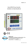
Bulletin IN-619
Series CS Low Cost Diaphragm Pressure Switches
Specifications – Installation and Operating Instructions
1/2 [12.7]
CONDUIT HOLE
11/16
[17.46]
1-1/16
[26.99]
3
[76.2]
3-3/4
[95.25]
1-5/16
[33.34]
The Series CS Low Cost Diaphragm Pressure Switch is
ideal for instrument panels, small compressors and general industrial applications. Visible set point and easy-towire SPDT snap switch reduce installation time. This
switch operates in any position and is vibration resistant.
INSTALLATION/MOUNTING
The control can be pipe mounted. Do not twist the case
when installing. Use wrench on the pressure connection
flats.
WIRING
All wiring must conform to the National Electrical code
and local regulations. Do not install control to handle
loads in excess of electrical rating shown in specifications
or as indicated on instructions inside control cover.
Connect wiring to screw terminals depending on the
action required. Common and High contacts will close
and Common and Low contacts will open when increasing pressure (or vacuum) reaches set point. The reverse
will occur when pressure (or vacuum) drops below the set
point less the deadband.
COMMON
ON HIGH
ON LOW
WIRING DIAGRAM
TOP VIEW
3-3/16
[80.96]
2-3/16
[55.56]
1/4 NPT
PHYSICAL DATA
Temperature Limits: -30 to 150°F (-34.4 to 65.6°C)
Pressure Connections: 1/4″ NPT(F)
Electrical Ratings: 12 A @ 120 VAC; 8 A @ 240 VAC; 7A
@ 277 VAC; 1/8 HP @ 120 VAC; 1/4 HP @ 240 VAC
Switch Type: SPDT snap acting
Conduit Opening: 1/2″
Wiring Connections: Three screw type, common, N.O.,
N.C.
Set Point Adjustment: Screw type, inside cover
Housing: Galvanized steel, NEMA 1
Diaphragm: Buna-N/Nylon
Calibration Spring: Plated steel
Installation: Any position
Weight: 1/2 lb. (0.23 kg)
Model
No.
Adjustable
Fixed Deadband
Operating Range
Maximum
Minimum
1-30" Hg. Vac.
1.5" Hg.
1" Hg. VAC
CS-1
2.5-75 cm Hg.Vac 3.8 cm Hg. Vac 2.5 cm Hg. Vac
10-100" w.c.
7" w.c.
5" w.c.
CS-3
2.5-250 cm w.c.
17.8 cm w.c. 12.7 cm w.c.
1-10 psig
0.4 psig
0.25 psig
CS-10
0.07-0.7 kg/cm2
0.03 kg/cm2
0.02 kg/cm2
1-30 psig
1.0 psig
0.5 psig
CS-30
0.07-2.1 kg/cm2
0.07 kg/cm2 0.035 kg/cm2
5 psig
1.5 psig
CS-150 10-150 psig 2
0.07-10.5 kg/cm
0.35 kg/cm2
0.1 kg/cm2
Max.
Pressure
30 psig
30 psig
30 psig
50 psig
175 psig
CAUTIONS: Do not oil any parts. Mount control securely.
Never exceed electrical rating for switch. Use only with
compatible.
WARNING
A failure resulting in injury or damage can be caused by
over-pressure, excessive vibration or pressure pulsation,
excessive temperature, corrosion of pressure containing
parts and movement assembly, electrical overload or
other misuse.
©Copyright 2001 Dwyer Instruments, Inc.
Printed in U.S.A. 4/01
MERCOID DIVISION
DWYER INSTRUMENTS, INC.
P.O. BOX 258 • MICHIGAN CITY, INDIANA 46361 U.S.A.
Phone: 219/879-8000
Fax: 219/872-9057
Lit-by-Fax: 888/891-4963
FR#90-442119-00 Rev. 2
www.dwyer-inst.com
e-mail: [email protected]