1
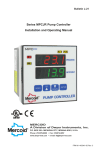
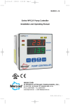
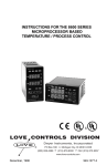
L-20:L-20
2/24/11
9:59 AM
Page 1
Bulletin L-20
Series MPC Pump Controller
Installation and Operating Manual
MERCOID
A Division of Dwyer Instruments, Inc.
P.O. BOX 258 • MICHIGAN CITY, INDIANA 46361, U.S.A.
Phone: 219/879-8000 • Fax: 219/872-9057
www.dwyer-inst.com • e-mail: [email protected]
FR # M1-443247-00 Rev. 4
L-20:L-20
2/24/11
9:59 AM
Page 1
CONTENTS
Dimensions . . . . . . . . . . . . . . . . . . . . . . . . . . . . . . . . . . . . . . . . . . . . . . . . . . . . . . . . . . . . . 1
Specifications . . . . . . . . . . . . . . . . . . . . . . . . . . . . . . . . . . . . . . . . . . . . . . . . . . . . . . . . . . . 2
Getting Started . . . . . . . . . . . . . . . . . . . . . . . . . . . . . . . . . . . . . . . . . . . . . . . . . . . . . . . . . . 3
Model Identification . . . . . . . . . . . . . . . . . . . . . . . . . . . . . . . . . . . . . . . . . . . . . . . . . . . . . . . 3
Installation . . . . . . . . . . . . . . . . . . . . . . . . . . . . . . . . . . . . . . . . . . . . . . . . . . . . . . . . . . . . . . 4
Wiring. . . . . . . . . . . . . . . . . . . . . . . . . . . . . . . . . . . . . . . . . . . . . . . . . . . . . . . . . . . . . . . . 5-7
Front Panel Functions . . . . . . . . . . . . . . . . . . . . . . . . . . . . . . . . . . . . . . . . . . . . . . . . . . . 8-9
Home Display . . . . . . . . . . . . . . . . . . . . . . . . . . . . . . . . . . . . . . . . . . . . . . . . . . . . . . . . . . . 9
Security Level Selection . . . . . . . . . . . . . . . . . . . . . . . . . . . . . . . . . . . . . . . . . . . . . . . . . . 10
Lead/Lag Operation. . . . . . . . . . . . . . . . . . . . . . . . . . . . . . . . . . . . . . . . . . . . . . . . . . . . . . 11
Seal Failure Operation . . . . . . . . . . . . . . . . . . . . . . . . . . . . . . . . . . . . . . . . . . . . . . . . . 11-12
Over Temperature Operation . . . . . . . . . . . . . . . . . . . . . . . . . . . . . . . . . . . . . . . . . . . . 12-13
Analog Retransmission Operation . . . . . . . . . . . . . . . . . . . . . . . . . . . . . . . . . . . . . . . . . . 13
Pump Run Time Operation . . . . . . . . . . . . . . . . . . . . . . . . . . . . . . . . . . . . . . . . . . . . . . . . 13
Serial Communication Operation . . . . . . . . . . . . . . . . . . . . . . . . . . . . . . . . . . . . . . . . . . . 14
Menu Selections . . . . . . . . . . . . . . . . . . . . . . . . . . . . . . . . . . . . . . . . . . . . . . . . . . . . . . . . 15
Secondary Menu . . . . . . . . . . . . . . . . . . . . . . . . . . . . . . . . . . . . . . . . . . . . . . . . . . . . . 15-16
Secure Menu . . . . . . . . . . . . . . . . . . . . . . . . . . . . . . . . . . . . . . . . . . . . . . . . . . . . . . . . 17-23
Alarm Type and Action. . . . . . . . . . . . . . . . . . . . . . . . . . . . . . . . . . . . . . . . . . . . . . . . . 20-22
Diagnostic Error Messages . . . . . . . . . . . . . . . . . . . . . . . . . . . . . . . . . . . . . . . . . . . . . 24-25
Programming Chart . . . . . . . . . . . . . . . . . . . . . . . . . . . . . . . . . . . . . . . . . . . . . . . . . . . 26-28
Programming Example . . . . . . . . . . . . . . . . . . . . . . . . . . . . . . . . . . . . . . . . . . . . . . . . 28-31
SPEC
Input
Input
Outp
Cont
Powe
132 t
Powe
Accu
Disp
Disp
Mem
Seria
Amb
F (40
Weig
Fron
Loop
Seal
Over
DIMENSIONS
4.500
(114.3)
3.774
(95.9)
0.530
(13.5)
Alarm
Set P
Powe
Temp
Com
Norm
Isola
3.774
(95.9)
3.596
(91.3 mm)
Stora
Agen
Panel cut-out: 3.620 x 3.620 in, +0.032/-0.000
(92 x 92 mm, +0.8/-0.0).
Allow for 0.5 in (13 mm) clearance
at the rear of the instrument.
Panel Thickness
0.250 (6.53 mm) Max.
1
Meets IP66 (UL Type 4X)
Modbu
L-20:L-20
..1
..2
..3
..3
..4
. 5-7
. 8-9
..9
. 10
. 11
1-12
2-13
. 13
. 13
. 14
. 15
5-16
7-23
0-22
4-25
6-28
8-31
4X)
2/24/11
9:59 AM
Page 2
SPECIFICATIONS
Inputs: 4 to 20 mA DC or 2.0 to 10.0 V DC selectable.
Input Impedance: Current input: 10 ohms, Voltage input: 100K ohms.
Output Ratings:
Control Relays: SPDT, rated 10A @ 240 VAC res., 1/4 hp @120 VAC,
1/3 hp @ 240 VAC.
Alarm Relays: SPST, 3A @ 240 VAC res., 1/10 hp @ 120 VAC.
Control Type: on/off, reverse or direct acting.
Power Requirements: 100 to 240 VAC nominal, +10%-15%, 50 to 400 Hz, single phase;
132 to 240 VDC nominal, +10%-15%.
Power Consumption: 7.5 VA maximum.
Accuracy: 0.25% of span, 1 least significant digit.
Display: Two 4 digit, 7 segment 0.56” high LED’s.
Display Resolution: 1 count.
Memory Backup: Nonvolatile memory (no batteries required).
Serial Communications: Optional RS-232 or RS-485 with Modbus® protocol.
Ambient Operating Temperature / RH: 14 to 131° F (-10 to 55° C) / 0 to 90% up to 104°
F (40° C) non-condensing, 10 to 50% at 131° F (55° C) non-condensing.
Weight: 16 oz. (454 g).
Front Panel Rating: Meets UL Type 4X (IP66).
Loop Power Supply (isolated): 24 VDC @ 50 mA, regulated.
Seal Failure (Moisture Sensor):
Power Supply to Moisture Sensor: 2.5 VDC.
Search Current: 3 micro amps.
Resistance Sensitivity: 10K to 500K ohms.
Resistance Resolution: 10K ohm steps.
Over Temperature:
Input: Dry contact on Transistor switch (NPN open collector type).
Current: 1 mADC.
Isolation: Shares common ground with transmitter input.
Alarm On-Off Differential: 1 count.
Set Point Range: Selectable.
Power Voltage Stability: 0.05% over the power voltage range.
Temperature Stability: 100 ppm / °C typical, 200 ppm / °C maximum.
Common Mode Rejection: 140 db minimum at 60 Hz.
Normal Mode Rejection: 65 db typical, 60 db at 60 Hz.
Isolation:
Relay: 1500 VAC to all other inputs and outputs.
24 VDC Loop Power: 500 VAC to other inputs and outputs.
Process Output: 500 VAC to other inputs and outputs.
Seal Failure Input: 500 VAC to other inputs and outputs.
Storage Temperature: -40 to 176° F (-40 to 80° C).
Agency Approvals: UL 508, CE.
Modbus® is a registered trademark of Schnieder Automation.
2
L-20:L-20
2/24/11
9:59 AM
Page 3
GETTING STARTED
1. Install the control as described on page 4.
2. Wire the control following the instructions on pages 5 through 7. Page 5 contains basic
wiring for the control. If using the Series MPC’s transmitter power supply follow the additional
directions on page 6. Wiring instructions for the 232 and 485 series communication options
is included on page 7.
3. Familiarize yourself with the front key pad functions and read the menu structure prior to
starting the programming process. A programming chart with the menu structure and spaces
to write your programming values is included on pages 26 through 28. This chart can be a
helpful tool to save time in programming. For further assistance programming examples are
included on pages 28 through 31.
MODEL IDENTIFICATION
Model MPC Options
Options:
232
RS-232 Modus®-RTU Serial Communications. Allows remote
computer to read and write all control parameters.
485
RS-485 Modbus®-RTU Serial Communications. Allows remote
computer to read and write all control parameters.
RV
Analog retransmission of input, 2 to 10 VDC.
Input Ranges
Process Input Types
The 0 to 20 mADC, 4 to 20 mADC, 0 to 10 VDC, and 2 to 10 VDC inputs are fully scalable
from a minimum of 100 count span placed anywhere within the range of
-1999 to +9999. Decimal point position is adjustable from the zero place (9999), tenths
(999.9), hundredths (99.99), or thousandths (9.999).
3
INSTA
Moun
or vib
in an
Selec
debu
From
be ag
From
one h
are c
L-20:L-20
basic
tional
ptions
rior to
paces
be a
es are
2/24/11
9:59 AM
Page 4
INSTALLATION
Mount the instrument in a location that will not be subject to excessive temperature, shock,
or vibration (see Specifications for specific tolerances). All models are designed for mounting
in an enclosed panel.
Select the position desired for the instrument on the panel. Prepare the panel by cutting and
deburring the required opening.
From the front of the panel, slide the housing through the cut out. The housing gasket should
be against the housing flange before installing.
From the rear of the panel slide the mounting collar over the housing. Hold the housing with
one hand and using the other hand, push the collar evenly against the panel until the springs
are compressed. The ratchets will hold the mounting collar and housing in place.
Figure 1 – Panel Cut Out Dimensions
Panel cut-out:
3.620 x 3.620 in,
+0.032/-0.000
(92 x 92 mm,
+0.8/-0.0)
CAUTION: It is not necessary to remove the instrument chassis from the
housing for installation. If the instrument chassis is removed from the
housing, you must follow industry standard practice for control and
protection against Electro-Static Discharge (ESD). Failure to exercise
good ESD practices may cause damage to the instrument.
lable
s
4
L-20:L-20
2/24/11
9:59 AM
Page 5
WIRING
Do not run transmitter wiring or other class 2 wiring in the same conduit as power leads. Use
only the probe or transmitter for which the control has been programmed. Maintain
separation between wiring of sensor, auxiliary in or out, and other wiring. See the ˝Secure
Menu˝ for input selection.
WIRI
Wire
show
Supply connections should be made in accordance with the National Electrical Code per
Article 300, and local regulations. All line voltage output circuits must have a common
disconnect and be connected to the same pole of the disconnect.
Input wiring for probe or transmitter is rated CLASS 2.
Control wiring is as shown in Figure 2 below.
Figure 2 - Wiring
Analog Retransmission
Pump 1 Over Temp
Pump 2 Over Temp
24 VDC
@
50 mA
Isolated
Voltage
Current
Pump 1
Output
Seal Pump 1
Sensor
Inputs Pump 2
Alarm 1
Contacts
Alarm 2
Contacts
Pump 2
Output
N.O.
COM.
N.O.
COM.
NOTES:
1. For supply connections use
No. 16 AWG or larger wires rated
for at least 167˚F (75˚C) or, in
accordance with an equivalent
national standard.
2. Maximum ambient temperature
rating 131˚F (55˚C).
3. Use copper conductors only.
4. Terminals 1-6, 11, 12, 21-32
are class 2 "SELV".
Line Input
100 to 240 VAC 50400 Hz. Single PH.
132 to 240 VDC 5VA.
Max. Output Ratings:
Relay: 10A @ 240 VAC Res.
1/4 HP @ 120 VAC
1/3 HP @ 240 VAC
Alarm: 3A @ 240 VAC Res.
1/10 HP, 120 VAC
290-3120
If not using pump over temperature inputs then jumper terminals 22 to 23 and 22 to 24.
5
For
trans
L-20:L-20
s. Use
intain
ecure
2/24/11
9:59 AM
Page 6
WIRING FOR TRANSMITTER INPUTS USING INTEGRAL POWER SUPPLY
Wire power and outputs as shown on previous page. Wiring for two-wire transmitters
shown below in Figure 3. All wiring shown in Figure 3 is Class 2.
Figure 3 - Transmitter Wiring
Connect Jumper between terminals 2 and 12
e per
mmon
Connect Transmitter Plus (+) to terminal 11
Connect Transmitter
minus (-) to terminal 3
Level
Transmitter
For three or four wire transmitters follow the wiring instructions provided with your
transmitter.
DO NOT wire the 24 Volt Power Supply across the input of the
control. Damage to the control input circuitry will result.
4.
6
L-20:L-20
2/24/11
9:59 AM
Page 7
WIRING FOR 485 AND 232 SERIAL COMMUNICATION OPTIONS
Wire power and outputs as shown on page 5. Wiring for options is shown in Figure 4 below.
All wiring shown below is Class 2. Shielded twisted pair is recommended for Option 485.
DO NOT run signal wiring in the same conduit or chase as the power wiring.
Erratic operation or damage to the control circuitry will result.
Figure 4 – Wiring for Options
1
21
22
23
24
25
11
26
2
12
3
13
DB-25 WIRING
(VIEWED FROM WIRE SIDE)
DATA IN
30
DATA OUT
32
DATA GROUND 31
1
2
3
4
5
6
7
8
9 10 11 12 13
14 15 16 17 18 19 20 21 22 23 24 25
4
14
5
15
6
7
16
Option 485 DIP Switch Positions*
Half Duplex*
Full Duplex
17
ON
18
8
9
10
OFF
1 2 3 4 5 6
27
Terminal
28
29
29
1 2 3 4 5 6
19
30
20
31
30
32
PIN
1
2
3
4
5
DESCRIPTION PIN DESCRIPTION
SHIELD
6
DSR
TRANSMIT
7
GROUND
RECEIVE
8
DCD
RTS
20 DTR
CTS
RS-232 DB-9 WIRING
(VIEWED FROM WIRE SIDE)
DATA OUT 32
DATA IN 30
DATA GROUND 31
1
2
6
31
3
7
4
8
5
9
PIN
1
2
3
4
5
6
7
8
32
Option 485
Y (receive -) Z (receive +) A (transmit -)* B (transmit +)*
Option 232
not used
data out
data ground
data in
*For half-duplex operation wire only A and B. Do not connect to Y and Z.
7
DESCRIPTION
DCD
RECEIVE
TRANSMIT
DTR
GROUND
DSR
RTS
CTS
Key f
L-20:L-20
2/24/11
10:00 AM
Page 8
FRONT PANEL FUNCTIONS
below.
85.
iring.
Key functions are as follows:
INDEX: Pressing the
INDEX key for 2 seconds will bring up the Secondary
menu starting at the SP1H menu item. Holding the key for 5 seconds will bring up the
Secure menu starting with the menu item SECr . Once in the menus, pressing the
INDEX key advances the display to the next menu item. May also be used in
conjunction with other keys as noted below.
SYSTEM TEST: When Test menu item is ˝On˝ depressing this key for three seconds
will make the MPC Pump Controller go through a system test. See page 18 for
explanation of system test function.
UP ARROW: Increments a value, changes a menu item, or selects the item to ON.
The maximum value obtainable is 9999 regardless of decimal point placement.
DOWN ARROW: Decrements a value, changes a menu item, or selects the item to
OFF. The minimum value obtainable is -1999 regardless of decimal point placement.
ENTER: The
ENTER key is used to store the value of menu items once they
are changed to a new value. If the
ENTER key is not pressed after changing the
value the item will revert to the previously stored value.
PUMP RUN TIME: Pressing this key will cause the MPC Pump Controller to display
the total run time (in hours) that the pump(s) have been on since the last reset.
8
L-20:L-20
2/24/11
10:00 AM
Page 9
INDEX & DOWN ARROW: Pressing these keys simultaneously
will allow backing up one menu item, or if at the first menu item they will cause
the display to return to the primary menu. If an alarm condition has occurred,
these keys may be used to reset the alarm.
INDEX & ENTER: Pressing these keys simultaneously and holding
them for 5 seconds allows recovery from the various error messages. The
following menu items will be reset:
SECU
Three
chang
displa
value
ENTE
secur
: Alarm inhibit
CHEC CAL : Check calibration error
To se
Correct the problems associated with the above conditions before using these reset keys.
More than one error could be present. Caution is advised since several items are reset at
one time.
uppe
ALiH
THE HOME DISPLAY
The home display is the normal display while the control is operating. If no errors or
functions are active, the HOME display will indicate the Process Variable (the level that is
being measured) on the top display and the SP1H value, Pump 1 On Set Point, on the
bottom display.
Error messages may over-ride the HOME display. See ERROR MESSAGES on pages 24
and 25.
While in the Secondary Menu, if no key is pressed for a period of 30 seconds, the display
will return to the HOME position displaying the process value. While in the Secure Menu,
if no key is pressed for a period of 60 seconds, the display will return to the HOME
position displaying the process value. Outputs are disabled (turned off) when the Secure
Menu is active.
9
The p
for fu
book.
Pass
Men
Seco
Secu
Seco
Secu
Seco
Secu
L-20:L-20
ause
ed,
eys.
et at
2/24/11
10:00 AM
Page 10
SECURITY LEVEL SELECTION
Three levels of security are provided. The SECr menu item security level may be viewed or
changed at any time regardless of the present security level in the Secure menu. The
display shows the current security level. To change security levels change the password
value using the
UP ARROW or
DOWN ARROW keys and pressing the
ENTER key. Refer to the password table (following) for the correct value to enter for the
security level desired.
To set the access level to, for example, 2, at the SECr menu item press the
UP ARROW key until the upper display shows the password,1101 . Press the
ENTER key. The display will blink, and return with the level value, 2, i n the
upper display.
The password values shown in the table cannot be altered. Retain a copy of these pages
for future reference. This is the only reference made to password values in this instruction
book.
at is
s 24
splay
enu,
Password Table
Menu
Secondary
Secure
Secondary
Secure
Secondary
Secure
Security Level
Status
Locked
Locked
Unlocked
Locked
Unlocked
Unlocked
Displayed Value Password
When Viewed
Value To Enter
2
1101
3
1011
4
111
ure
10
L-20:L-20
2/24/11
10:00 AM
Page 11
LEAD/LAG OPERATION
The Mercoid® MPC pump controller is designed to easily operate a pair of pumps in the
most efficient manner possible. The controller has a 'lead/lag' feature that allows two
pumps to operate in an alternating fashion to minimize wear.
The Mercoid® MPC pump controller has a pair of set points each for pump 1 and pump 2. If
the lead/lag feature is turned off, SP1H and SP1L control pump 1 and SP2H and SP2L control
pump 2. If the lead/lag feature is turned on, pumps 1 and 2 will be controlled in the
alternating fashion described below. In all cases the P1 lamp will indicate activity of pump 1
and the P2 lamp will indicate activity of pump 2. The lead/lag operation is set in the Secure
menu with the item LdL9.
Lead/Lag On
After installation, set the SP1H to the high level (pump on point) for standard operation. Set
SP1L to the low level (pump off point). Set the SP2H to the level where you want BOTH
pumps to turn on (emergency pump on). Set the SP2L to the level where you want the
second pump to turn off (emergency pump off).
The controller will not allow you to set SP1H below SP1L, SP1L above SP1H, SP2H below
SP2L, or SP2L above SP2H. The controller will not allow you to set any set point or alarm
point above or below the programmed scale. No error messages are generated. The
displayed value will stop at an allowable point just above (or below, as the case may be)
the maximum or minimum allowed.
In normal operation, when the SP1H point is reached, one of the pumps will turn on. When
lead/lag is turned on, pumps 1 and 2 will alternate. If the level reaches the SP2H point, both
pumps will be turned on until the SP2L point is reached, where one of the pumps will turn
off. When SP1L is reached, remaining running pump will turn off. The last pump off will not
be the next pump on.
Lead/Lag Off
If lead/lag is turned off, SP1H and
There is no alternating function.
SP1L
control pump 1 and
SP2H
and
SP2L
control pump 2.
SEAL FAILURE OPERATION
The Mercoid® MPC Pump Controller is designed to work with most types of submersible
pump moisture sensors to detect outer seal failure. Most often the moisture sensor is a
conductance device that detects moisture in the oil chamber indicating an outer seal failure.
Using a 2.5 VDC power supply sent to the moisture sensor the MPC Pump Controller
monitors the resistance between the probe lead wires or the single probe lead wire and
ground. The resistance set point is adjustable over the range of 10K to 500K ohms
adjustable in 10K ohm steps, and is set with Secondary menu items SFS1 and SFS2. When
the resistance of the moisture sensor decreases below the resistance set point the MPC
controller goes into the programmed seal failure mode.
In the
the c
there
contr
lamp
If PSF
cond
is on
turne
indica
being
autom
the a
manu
Once
P1SF
corre
reset
If the
OVE
Most
of the
point
signa
In the
cond
is an
pump
the le
servic
disco
autom
and S
If P0t
the la
the p
P10t
cann
Once
P10t
pump
pump
temp
11
L-20:L-20
e
p 2. If
ontrol
mp 1
ecure
Set
ow
m
2/24/11
10:00 AM
Page 12
In the Secure menu the value of PSF is programmed for the action of the MPC based on
the condition of a seal failure. If set to ˝AUt0˝ when pump moisture sensor indicates that
there is a seal failure condition then the corresponding pump seal failure lamp is lit on the
controller. The pump will remain in service with only the lamp indication of failure. The
lamp will be turned off automatically when the seal failure condition has ceased.
If PSF is set to ˝rES˝ when pump moisture sensor indicates that there is a seal failure
condition then the corresponding pump seal failure lamp is lit on the controller. If the MPC
is only being used with one pump or being used with two pumps with the lead/lag function
turned off then no action is taken by the MPC with the operation of the pumps. The failure
indication lamp will be manually reset as described in the next paragraph. If the MPC is
being used with two pumps with the lead/lag function turned on then the failed pump will
automatically become the lag pump, the remaining pump will become the lead pump, and
the alternation will be discontinued. The lamp indication and pump alternation can be
manually reset as described in the next paragraph.
Once the pump has been repaired the seal failure action can be reset with the values of
P1SF and P2SF in the Secondary menu. The item P1SF or P2SF will display FA1L if the
corresponding pump has met the condition of a seal failure. Press the
ENTER key to
reset. If the pump moisture sensor is still in the fail condition then the control will not reset.
If the moisture sensor is no longer in the fail condition then the display will revert to ˝----˝.
e)
hen
both
urn
not
mp 2.
le
a
ailure.
d
When
PC
OVER TEMPERATURE OPERATION
Most pumps have an installed normally closed thermostat for over temperature protection
of the pump. The thermostat has a preset value from the pump manufacturer at which
point the pump needs to be shut down. The Mercoid® MPC detects when the thermostat
signal changes to open and shuts down the pump.
In the Secure menu the value of P0t is programmed for the action of the MPC based on the
condition of the over temperature. When the pump temperature sensor indicates that there
is an over temperature condition the pump will be held out of service and the corresponding
pump over temperature lamp is lit on the controller. If using the MPC with two pumps with
the lead/lag function turned on then the failed pump will automatically be taken out of
service, the remaining pump will become the lead pump, and the alternation will be
discontinued. When controlling two pumps with the lead/lag function off the failed pump will
automatically be taken out of service and the remaining pump will be controlled by the SP1H
and SP1L set points.
If P0t is set to ˝AUt0˝ then the pump will be automatically placed back into service and
the lamp turned off when the over temperature condition has ceased. If set to ˝rES ˝ then
the pump will remain out of service and the lamp lit until the corresponding manual reset
P10t or P20t is reset in the Secondary menu (described in the next paragraph). The pump
cannot be brought back into service until the over temperature condition has ceased.
Once the pump has cooled down the MPC Pump Controller can be reset with the values of
P10t and P20t in the Secondary menu. The item P10t or P20t will display FA1L if the
pump has met the condition of over temperature. Press the
ENTER key to reset. If the
pump temperature sensor is still in the fail condition then the control will not reset. If the
temperature input is no longer in the fail condition then the display will revert to ˝----˝.
12
L-20:L-20
2/24/11
10:00 AM
Page 13
ANALOG RETRANSMISSION OPERATION
The analog retransmission allows the Process Variable to be sent as an analog signal to
an external device. The signal may be either 2 to 10 VDC (option RV) or 4 to 20 mADC
(standard). The output may be changed in the field from one to the other by the toggle
switch located on the top printed circuit board, factory standard is mADC.
Wire the output as shown on page 5.
To set up the analog retransmission, first determine the scale range that the analog signal
will represent. The maximum scale is 9999 counts. In the Secure menu set P0L for the
scale value that will be represented by the low end of the analog signal (2 Volts or 4 mA).
Set P0H for the scale value that will be represented by the high end of the analog signal
(10 Volts or 20 mA). Operation is automatic. There are no further programming steps
required. The values of P0L and P0H must be within the programmed scale range. The
scale range is set by the SCAL and SCAH in the Secure menu.
PUMP RUN TIME OPERATION
The pump run time is indicated in hours of operation since the last time that the run time
meter was reset for a specific pump. The
Pump Run Time key on the front of the
unit will display run time for both pumps when depressed. Run time for pump 1 is in the
top display and pump 2 is in the lower display. To reset the pump run time go to the menu
items P1rn and P2rn in the Secondary Menu. When in the corresponding menu item hold
the
ENTER button for approximately two seconds. The display will blank out for
about 1 second and the run time will display 0. These menu items can be locked out by
the PrSt menu item in the Secure Menu.
OPTI
The s
remo
RS-4
Wire
contro
transm
for ha
comm
Selec
items
EFFE
THE
In ope
To pre
Seco
(The
If you
to set
is set
addre
nAt, t
L0rE
13
L-20:L-20
l to
DC
e
ignal
e
mA).
nal
e
me
he
he
menu
hold
r
by
2/24/11
10:00 AM
Page 14
OPTION 232, 485 SERIAL COMMUNICATION OPERATION
The serial communications options allow the control to be written to and read from a
remote computer or other similar digital device. Communication is allowed either through a
RS-485 (Option 485) port, or a RS-232 (Option 232) port.
Wire the communication lines as shown on Page 7. Wiring for the RS-485 is run from
control to control in a daisy chain fashion with a termination resistor (120 ohms) across the
transmit and receive terminals of the last control in the chain. Set the RS-485 DIP switch
for half or full duplex as appropriate for your application. The DIP switch is located on the
communications board plugged into the center of the bottom board of the control.
Select the control address and communication baud rate with the Addr and bAUd menu
items in the Secure Menu. THE BAUD RATE AND ADDRESS MENU ITEMS WILL TAKE
EFFECT ON THE NEXT POWER UP OF THE CONTROL. BE SURE TO POWER CYCLE
THE CONTROL BEFORE USING THE NEW BAUD RATE AND ADDRESS.
In operation, you have the option of preventing a write command from the host computer.
To prevent the host from writing to the control change the L0rE menu item in the
Secondary Menu to L0C. To allow the host to write commands to the control set L0rE to rE.
(The host does have the ability to change the L0rE state, but it is not automatic.)
If your system depends on constant reading or writing to and from the host, you may wish
to set the No Activity Timer (nAt) to monitor the addressing of the control. When the L0rE
is set to rE and the nAt is set to any value other than 0FF, the control will expect to be
addressed on a regular basis. If the control is not addressed in the time set by the value of
nAt, then the control will display the error message CHEC LorE. To clear the message set
L0rE to L0C.
14
L-20:L-20
2/24/11
10:00 AM
Page 15
MENU SELECTIONS
Notation Conventions for the Menus
Because of the number of features available in this control, information is included that
may not apply to your specific control. All usable features are included in this book, but
may not be used in your process. To increase clarity the following conventions are used:
P1rn
1. Certain features or functions shown in this book are contextual. This means that Menu
Items may or may not appear, depending on other Menu Item selections. Whenever this
occurs, a notation is made in the Menu Item that ˝controls˝ or ˝directs˝ other menu items. If
you are looking for a particular menu item and can't find it, check the menu item that is its
˝control˝ for proper setting.
2. The ˝#˝ symbol is used in two ways. It is used inside a group of characters to indicate
which set point function (SP1 or SP2) is being affected. It is also used before a group of
characters of a menu item to indicate that there may be more than one selection or value
for that menu item.
P1SF
Secondary Menu
Press the
INDEX key for 2 seconds to start the menu. Press
INDEX to advance
to the next menu item. Press
UP ARROW or
DOWN ARROW
to change the value in the display. Press
ENTER to retain the value.
SP1H
Pump 1 On Set Point. Factory Default
23.1
SP1L
Pump 1 Off Set Point. Factory Default
0.0
SP2H
Pump 2 On Set Point. Factory Default
23.1
SP2L
Pump 2 Off Set Point. Factory Default
A1Hi
Alarm 1 High: Factory Default
A2Lo
Alarm 2 Low: Factory Default
SFS1
Pump 1 Seal Failure Set Point: Select 10 to 500 in any increment of 10.
Sets the resistance set point at which the controller will trip the Seal Failure
based on the input from the pump moisture sensor. The controller will
activate the Seal Failure condition based on a decrease of resistance to the
set point. Selectable resistance range is from 10K to 500K ohms with the
factory default at 120K ohms.
SFS2
Pump 2 Seal Failure Set Point: Select 10 to 500 in any increment of 10.
Sets the resistance set point at which the controller will trip the Seal Failure
based on the input from the pump moisture sensor. The controller will
activate the Seal Failure condition based on a decrease of resistance to the
set point. Selectable resistance range is from 10K to 500K ohms with the
factory default at 120K ohms.
P2rn
P2SF
P10t
(feet).
(feet).
P20t
23.1
2.0
0.0
(feet).
(feet).
(feet).
(feet).
15
L-20:L-20
at
ut
ed:
enu
his
ms. If
s its
ate
of
alue
2/24/11
10:00 AM
Page 16
P1rn
Pump 1 Run Time: Total ON Time for Pump 1 in HOURS since last reset
(0000 - 9999 hours).
P2rn
Pump 2 Run Time: Total ON Time for Pump 2 in HOURS since last reset
(0000 - 9999 hours).
P1SF
Pump 1 Reset for Seal Failure. Displays ˝----˝ when pump 1 is in normal operating
condition based on seal failure input. Displays FA1L if pump 1 has met the
condition of a seal failure. Press the
ENTER key to reset. If pump 1 seal
failure is still in the fail condition then the control will not reset. If the seal failure
input is no longer in fail condition then the display will revert to ˝----˝.
P2SF
Pump 2 Reset for Seal Failure. Displays ˝----˝ when pump 2 is in normal operating
condition based on seal failure input. Displays FA1L if pump 2 has met the condition of seal failure. Press the
ENTER key to reset. If pump 2 seal failure is
still in the fail condition then the control will not reset. If the seal failure input is no
longer in fail condition then the display will revert to ˝----˝.
P10t
Pump 1 Reset for Over Temperature. Displays ˝----˝ when pump 1 is in normal
operating condition based on temperature input. Displays FA1L if pump 1 has met
the condition of over temperature. Press the
ENTER key to reset. If pump 1
temperature input is still in the fail condition then the control will not reset. If the
temperature input is no longer in fail condition then the display will revert to ˝----˝.
P20t
Pump 2 Reset for Over Temperature. Displays ˝----˝ when pump 2 is in normal
operating condition based on temperature input. Displays FA1L if pump 2 has me
the condition of over temperature. Press the
ENTER key to reset. If pump 2
temperature input is still in the fail condition then the control will not reset. If the
temperature input is no longer in fail condition then the display will revert to ˝----˝.
ance
16
L-20:L-20
2/24/11
10:00 AM
Page 17
Secure Menu
Press the
INDEX key for 5 Seconds to start the menu. Press
INDEX to advance
to the next menu item. Press
UP ARROW or
DOWN ARROW to change the
value in the display. Press
ENTER to retain the value. OUTPUTS ARE DISABLED
(TURNED OFF) WHILE CONTROL IS IN THE SECURE MENU.
SECr
Security Code: See the Security Level Selection and the Password Table on
page 10, in order to enter the correct password. Factory Default is 4 .
SCAH
Scale High: Select100 to 9999 counts above SCAL. The total span between
and SCAH must be within 11998 counts. Maximum setting range is -1999 to
+9999 counts. Factory Default is 23.1.
SCAL
SCAL
Scale Low: Select 100 to 9999 counts below SCAH. The total span between SCAL
and SCAH must be within 11998 counts. Maximum setting range is -1999 to
+9999 counts. Factory Default is 0.0.
dPt
Decimal Point Positioning: Select 0 , 0.0, 0.00, or 0.000. All Menu items related
to the input will be affected. Factory default is 0.0.
S1St
Set Point 1 State: Select P1n or P0ut. Factory default is P0ut.
P1n
Pump In (Direct Action). As the input increases the output
will increase.
P0ut
Pump Out (Reverse Action). As the input increases the output
will decrease.
S2St
0SUP
1nP
P0t
PSF
Set Point 2 State: Select P1n, P0ut or 0FF. Factory default is P0ut.
Pump In (Direct Action). As the input increases the output
will increase.
P0ut
Pump Out (Reverse Action). As the input increases the output
will decrease.
0FF
This setting is for applications when the MPC is used with only one
pump systems. All Menu items relating to Set Point 2 will not
appear.
P1n
LdL9
1nPC
Lead / Lag: Select 0n or 0FF. Factory default is 0n. (See page 11)
0n
The Lead/Lag function is enabled. The outputs of SP1 and
will alternate.
0FF
The Lead/Lag function is disabled.
SP2
Input Correction: Select ±500 counts. This feature allows the input value to
be changed to agree with an external reference or to compensate for
sensor error. Note:1nPC is reset to zero when the input type is changed, or
when decimal position is changed.
17
tESt
L-20:L-20
9
to
10:00 AM
Page 18
0SUP
Zero Suppression: Select 0n or 0FF. Factory default is 0n.
0FF
The input range will start at 0 (zero) Input.
0n
The input range will start at 4.00 mA or 2.00 V.
1nP
Input Type: Select one of the following. Refer to the Input wiring section for
the proper wiring. Factory Default is Curr.
Curr
DC Current Input 0.0 to 20.0 or 4.0 to 20.0 mA.
UoLt
DC Voltage Input 0.0 to 10.0 or 2.0 to 10.0 volts.
---Reserved
P0t
Pump Over Temperature: Select AUt0 or rES. When pump temperature sensor
indicates that there is an over temperature condition the pump will be held out of
service and the corresponding pump over temperature lamp is lit on the controller.
If using the MPC with two pumps and lead/lag on then the remaining pump
becomes the lead pump. If lead/lag is turned off then the remaining pump
becomes controlled by Set Point 1. See page 12.
AUt0
The pump will be automatically placed back into service and the
lamp turned off when the over temperature condition has ceased.
rES
The pump will remain out of service and the lamp lit until the
corresponding manual reset P10t or P20t is reset in the
Secondary menu. The pump cannot be brought back into service until
the over temperature condition has ceased.
PSF
Pump Seal Failure: Select AUt0 or rES. See page 11.
AUt0
When pump moisture sensor indicates that there is a seal failure condition
the corresponding pump seal failure lamp is lit on the controller. The pump
will remain in service with only the lamp indication of failure. The lamp will
automatically turn off when failure condition ceases.
rES
When pump moisture sensor indicates that there is a seal failure
condition the corresponding pump seal failure lamp is lit on the
controller. If the MPC is being used with two pumps and the lead/lag
feature turned on then the failed pump will automatically become the lag
pump, the remaining pump the lead pump, and the alternation
discontinued. The seal failure action is reset manually with the values of
P1SF and P2SF in the Secondary menu. The control will only reset if the
pump moisture sensor is no longer in a failed condition.
tESt
System Test: Select 0n or 0FF. When 0n is selected the ˝System Test˝ key on the
front panel will be activated. By depressing this key for 3 seconds the controller
will simulate an input from SCAL to SCAH and back to SCAL over a period of 32
seconds. This test will run continuously until the SYSTEM TEST key is pressed
again. When the controller is in System Test Mode the lamp above the System
Test Key will be ON.
nce
D
2/24/11
SCAL
ed
18
L-20:L-20
2/24/11
10:00 AM
Page 19
PrSt
Pump Run Time Reset: Select 0n or 0FF. Selecting 0n will allow Pump Run
Time to be reset in the Secondary menu while an 0FF selection will not allow
Pump Run Time to be reset.
SPH
Set Point High: Select from the highest input range value to SPL value. This will set
the maximum SP1H or SP2H value that can be entered. The value for SP1H or
SP2H will stop moving when this value is reached. Factory Default is 23.1.
SPL
Set Point Low: Select from the lowest input range value to SPH value. This will set
the minimum SP1L or SP2L value that can be entered. The value for SP1L or SP2L
will stop moving when this value is reached. Factory Default is 0.0.
S1Pi
S1iH
S2Pi
Setpoint 1 Power Interrupt. Select 0n or 0FF. Factory default is 0FF.
0n
Alarm Power Interrupt is 0n. Output will automatically reset on
power-up if no alarm condition exists.
0FF
Alarm Power Interrupt is 0FF. Output will be in the alarm condition
on power-up regardless of condition of process.
Setpoint 1 Inhibit: Select 0n or 0FF. Factory default is 0FF.
0n
Alarm Inhibit is 0n. Alarm action is suspended until the process
value first enters a non-alarm condition.
0FF
Alarm Inhibit is 0FF.
Setpoint 2 Power Interrupt. Select 0n or 0FF. Factory default is 0FF.
0n
Alarm Power Interrupt is 0n. Output will automatically reset on
power-up if no alarm condition exists.
0FF
Alarm Power Interrupt is 0FF. Output will be in the alarm condition
on power-up regardless of condition of process.
S2iH
Setpoint 2 Inhibit: Select 0n or 0FF. Factory default is 0FF.
0n
Alarm Inhibit is 0n. Alarm action is suspended until the process
value first enters a non-alarm condition.
0FF
Alarm Inhibit is 0FF.
S2ti
Setpoint 2 Time Delay. Select from 0 to 60 seconds. Factory default is 0. This will
set a time delay for setpoint 2 on power up of the MPC that will assure that
setpoint 2 will not be brought into use until after the programmed time delay.
PEA
The Peak feature stores the highest input the control has measured since the last
reset or Power On. At Power On PEA is reset to the present input. To manually
reset the value PEA must be in the lower display. Press the
ENTER key to
reset. PEA will be reset and display the present input value.
UAL
The Valley feature stores the lowest input the Controller has measured since the
last reset or Power On. At Power On UAL is reset to the present input. To
manually reset the value UAL must be in the lower display. Press the
ENTER key. UAL will be reset and display the present input value.
19
ALAR
Cauti
enda
When
differe
Since
progr
one in
point
were
When
alarm
requir
will co
When
progr
subse
If Ala
the p
as if a
secon
The f
AL1
L-20:L-20
2/24/11
10:00 AM
Page 20
ALARM TYPE AND ACTION
Caution: In any critical application where failure could cause expensive product loss or
endanger personal safety, a redundant limit controller is required.
When setting an alarm value for an absolute alarm (A1t =
simply set the value at which the alarm is to occur.
set
set
When setting the alarm value for a deviation alarm (A1t =
difference in value from the Set Point (SP1H) desired.
dE
or
A2t
=
AbS
or
dE),
A2t
=
AbS),
set the
SP2L
Since the input for the MPC is driven from a transmitter, the input display can be
programmed in different ways. Regardless of the position of the decimal point, a change of
one in the right most digit is referred to as a count. For example, if there were no decimal
point selected, a change from 235 to 236 is a change of one count. If the decimal point
were selected at 0.0, a change of 23.5 to 23.6 is a change of one count.
When setting up an alarm for deviation the deviation is set in counts. For example if a low
alarm is required to be 5 counts below the SP1H, then set A#Lo to -5. If a high alarm is
required 20 counts above the SP1H, then set A#Hi to +20. If SP1H is changed, the alarm
will continue to hold the same relationship as originally set.
When Alarm Power Interrupt, A#P, is programmed ON and Alarm Reset, A#rE, is
programmed for Hold, the alarm will automatically reset upon a power failure and
subsequent restoration if no alarm condition is present.
If Alarm Inhibit, A#iH is selected ON, an alarm condition is suspended upon power up until
the process value passes through the alarm set point once. Alarm inhibit can be restored
as if a power up took place by pressing both the
INDEX and
ENTER keys for 5
seconds.
WARNING: IF INHIBIT IS ON AND A POWER FAILURE OCCURS DURING
A HIGH ALARM, RESTORATION OF POWER WILL NOT CAUSE THE
ALARM TO OCCUR IF THE PROCESS VALUE DOES NOT FIRST DROP
BELOW THE HIGH ALARM SETTING. DO NOT USE THE ALARM INHIBIT
FEATURE IF A HAZARD IS CREATED BY THIS ACTION. BE SURE TO
TEST ALL COMBINATIONS OF HIGH AND LOW ALARM INHIBIT ACTIONS
BEFORE PLACING CONTROL INTO OPERATION.
s will
e last
ly
to
the
The following menu items apply only to the alarms.
AL1
Alarm 1 function: Select 0FF, Lo, Hi, or HiLo. Factory default is Hi.
0FF
Alarm 1 is disabled. No Alarm 1 menu items appear in the
Secondary or Secure menus.
Lo
Low Alarm Only. A1Lo appears in the Secondary Menu.
20
L-20:L-20
2/24/11
Hi
HiLo
SF
0t
SF0t
10:00 AM
Page 21
High Alarm Only. A1Hi appears in the Secondary Menu.
High and Low Alarms. Both A1Lo and A1Hi appear in the Secondary
Menu, and share the same Alarm 1 Relay output.
Seal Failure ONLY will trigger Alarm.
Over Temperature Failure ONLY will trigger Alarm
Both Seal Failure and Over Temperature Failure will trigger Alarm.
AL2
With the Alarm Function settings on 0FF, SF, 0t, SF0t certain alarm related menu items
will disappear as those menu items do not apply.
A1t
Alarm 1 Type: Select AbS or dE. Factory default is AbS.
AbS
Absolute Alarm that may be set anywhere within the values of SCAL and
SCAH and is independent of SP1H.
dE
Deviation Alarm that may be set as an offset from SP1H. As SP1H is
changed the Alarm Point will track with SP1H.
With
will d
A2t
A1rE
Alarm 1 Reset: Select 0n0F or HoLd. Factory default is 0n0F.
0n0F
Automatic Reset.
HoLd
Manual Reset. Reset (acknowledge) by simultaneously pressing the
INDEX &
DOWN ARROW keys for 5 seconds.
A1Pi
Alarm 1 Power Interrupt: Select 0n or 0FF. Factory default is
0n
Alarm Power Interrupt is 0n.
0FF
Alarm Power Interrupt is 0FF.
A1iH
Alarm 1 Inhibit: Select 0n or 0FF. Factory default is 0FF.
0n
Alarm Inhibit is 0n. Alarm action is suspended until the process
value first enters a non-alarm condition.
0FF
Alarm Inhibit is 0FF.
A1St
Alarm 1 Output State: Select CL0S or 0PEn. Factory default is
CL0S
Closes Contacts at Alarm Set Point.
0PEn
Opens Contacts at Alarm Set Point.
A1LP
Alarm 1 Lamp: Select 0 on or 0oFF. Factory default is 0 on.
0 on
Alarm Lamp is ON when alarm contact is closed.
0oFF
Alarm Lamp is OFF when alarm contact is closed.
A2St
A1td
Alarm 1 Time Delay: Select 0FF or1 to 8000 seconds. Factory default is 0FF.
0FF
Alarm function will operate when triggered at programmed Alarm
Set Point.
1-8000 Alarm function will only operate once the programmed time has
elapsed after the alarm was triggered by the Alarm Set Point.
A2LP
A2rE
0FF.
A2Pi
A2iH
21
CL0S.
A2td
L-20:L-20
AL2
y
ms
and
2/24/11
10:00 AM
Page 22
Alarm 2 function: Select 0FF, Lo, Hi, HiLo, SF, 0t, or SF0t. Factory default is Lo.
0FF
Alarm 2 is disabled. No Alarm 2 menu items appear in the
Secondary or Secure menus.
Lo
Low Alarm Only. A2Lo appears in the Secondary Menu.
Hi
High Alarm Only. A2Hi appears in the Secondary Menu.
HiLo
High and Low Alarms. Both A2Lo and A2Hi appear in the Secondary
Menu, and share the same Alarm 2 Relay output.
SF
Seal Failure ONLY will trigger Alarm.
0t
Over Temperature Failure ONLY will trigger Alarm
SF0t
Both Seal Failure and Over Temperature Failure will trigger Alarm.
With the Alarm Function settings on 0FF, SF, 0t, SF0t certain alarm related menu items
will disappear as those menu items do not apply.
A2t
Alarm 2 Type: Select AbS or dE. Factory default is AbS.
AbS
Absolute Alarm that may be set anywhere within the values of SCAL
and SCAH and is independent of SP1H.
dE
Deviation Alarm that may be set as an offset from SP1H. As SP1H
is changed the Alarm Point will track with SP1H.
A2rE
Alarm 2 Reset: Select 0n0F or HoLd Factory default is 0n0F.
0n0F
Automatic Reset.
HoLd
Manual Reset. Reset (acknowledge) by simultaneously pressing the
INDEX &
DOWN ARROW keys for 5 seconds.
A2Pi
Alarm 2 Power Interrupt: Select 0n or 0FF. Factory default is
0n
Alarm Power Interrupt is On.
0FF
Alarm Power Interrupt is OFF.
A2iH
Alarm 2 Inhibit: Select 0n or 0FF. Factory default is 0FF.
0n
Alarm Inhibit is On. Alarm action is suspended until the process
value first enters a non-alarm condition.
0FF
Alarm Inhibit is OFF.
A2St
Alarm 2 Output State: Select CL0S or 0PEn. Factory default is
CL0S
Closes Contacts at Alarm Set Point.
0PEn
Opens Contacts at Alarm Set Point.
A2LP
Alarm 2 Lamp: Select 0 on or 0oFF. Factory default is 0 on.
0 on
Alarm Lamp is ON when alarm contact is closed.
0oFF
Alarm Lamp is OFF when alarm contact is closed.
A2td
Alarm 2 time Delay: Select 0FF or1 to 8000 seconds. Factory default is 0FF.
0FF
Alarm function will operate when triggered at programmed Alarm
Set Point.
1-8000 Alarm function will only operate once the programmed time has
elapsed after the alarm was triggered by the Alarm Set Point.
22
0FF.
CL0S.
L-20:L-20
FiLt
P0H
P0L
2/24/11
10:00 AM
Page 23
Digital Filter: Select 0FF or1 to 99. In some cases the time constant of the
sensor, or noise could cause the display to jump enough to be unreadable. If this
value is set too high, controllability will suffer. Factory default is 3.
(Analog Retransmission Output, see page 13) Process Output High:
Select from any value greater than P0L to 9999 counts. Factory default is
23.1.
(Analog Retransmission Output, see page 13) Process Output Low:
Select -1999 counts to any value less than P0H. Factory default is 0.0.
DIAG
Disp
No
disp
light
FA1L
tESt
The remaining menu items appear if the corresponding option was purchased with the
control.
L0rE
(Option 232 and 485, Serial Communications) Local / Remote Status:
Select L0C or rE. Factory default is rE.
L0C
The host computer is advised not to send remote commands. Any write
commands sent to the controls will be rejected.
rE
The host computer is allowed to send write commands. If the control is not
addressed within the time set in the nAt (No Activity Timer, see Secure
Menu) the CHEC L0rE error message will be displayed.
Addr
(Option 232 or 485, Serial Communications) Control Address:
Set from1 to FF. This number (hexadecimal, base 16) must match the address
number used by the host computer. Factory default is 32.
bAUd
(Option 232 or 485, Serial Communications) Communication Baud Rate:
Select 300, 1200, 2400, 4800, 9600, or 19200. This number must match the
baud rate used by the host computer. Factory default is 9600.
nAt
(Option 232 or 485, Serial Communications) No Activity Timer:
Set from 0FF or1 to 99 minutes. Factory default is 0FF.
1-99
Maximum time between host computer accesses. If timer counts to 0,
CHEC / L0rE will be displayed.
0FF
No Activity Timer function is disabled.
Stor
(Option 232 or 485, Serial Communications) Store to EEPROM:
Select YES or no.
YES
Menu item changes made through serial communications are stored
directly to EEPROM.
no
Menu item changes made through serial communications are
stored in RAM. (Settings are lost if power is disconnected)
23
CHEC
LorE
L-20:L-20
2/24/11
10:00 AM
Page 24
DIAGNOSTIC ERROR MESSAGES
f this
.1.
Display
No
display
lighted
FA1L
tESt
e
e
not
CHEC
LorE
ess
Meaning
Display is blank.
Instrument is not
getting power, or
the supply voltage
is too low.
Fail test appears
upon power up if
the internal
diagnostics detect
a failure. This
message may
occur during
operation if a
failure is detected.
Displays flash.
SP Outputs
Set point
outputs inactive
Alarms inactive
Action Required
Check that the power supply
is on, or that the external
fuses are good.
Set point
outputs inactive
Alarms inactive
This message
appears if the
Serial
Communications
has timed out.
Set point
outputs active
Alarms inactive
The display alternates
between FA1L tESt and one
of the following messages:
FACt dFLt: Memory may be
corrupted. Press the ENTER
key and the DOWN ARROW
key to start the factory
default procedure. Recheck
controller programming. rEt
FACt: Unrecoverable error,
return to factory for service.
Restore the communications
line and switch the LorE to
L0C.
e
0,
d
24
L-20:L-20
2/24/11
10:00 AM
Page 25
DIAGNOSTIC ERROR MESSAGES
Display
UFL
or
0FL
CHEC
CAL
ArEA
(Alternates
with PV)
ArEA
Meaning
Underflow or
Overflow: Process
value has
exceeded input
range ends.
Check calibration
appears as an
alternating
message if the
instrument
calibration nears
tolerance edges.
Check calibration
appears as a
flashing message if
the instrument
calibration exceeds
specification.
This message
appears if the
ambient
temperature of the
control approaches
the ends of
tolerance. This
message appears
if the ambient
temperature of the
control is out of
range or RJC
sensor is broken.
SP Outputs
Set point
outputs active
Alarms active
Action Required
Input signals may normally
go above or below range
ends. If not, check input and
correct.
Set point
outputs active
Alarms active
Remove the instrument for
service and / or recalibration.
To reset use the INDEX &
ENTER keys.
Set point
outputs
inactive
Alarms active
Remove the instrument for
service and / or recalibration.
To reset use the INDEX &
ENTER keys.
Set point
outputs active
Alarm active
Correct the ambient
temperature conditions.
Ventilate the area of the
cabinet or check for clogged
filters. If RJC broken, return
to factory for service.
Correct the ambient
temperature conditions.
Ventilate the area of the
cabinet or check for clogged
filters. If RJC broken, return
to factory for service.
PROG
Use t
want
Menu
Prim
Menu
Seco
Set point
outputs active
Alarms active
Menu
Se
25
L-20:L-20
2/24/11
10:00 AM
Page 26
PROGRAMMING CHART
Use the charts on this and the next page to record the values in your application. You may
want to photocopy the pages if you plan to make programming changes.
Menu
Primary
Menu
Secondary
Menu
Secure
Item
PV SP1H
Default
XXXX
Set At
Description
Home Position, Process Variable &
SP1H's Value displayed
Item
SP1H
SP1L
SP2H
SP2L
A1Hi
A2Lo
SFS1
SFS2
P1rn
Default
23.1
0.0
23.1
0.0
23.1
2.0
120
120
XXXX
Set At
P2rn
XXXX
P1SF
P2SF
P1OT
----------
P2OT
----
Description
Set Point 1 value (default is in feet)
Set Point 1 off value (default is in feet)
Set Point 2 value (default is in feet)
Set Point 2 off value (default is in feet)
Alarm 1 (high) value (default is in feet)
Alarm 2 (low) value (default is in feet)
Pump 1 Seal Failure Set Point
Pump 2 Seal Failure Set Point
Total ON Time for Pump 1 in HOURS
since last reset
Total ON Time for Pump 2 in HOURS
since last reset
Pump 1 Reset for Seal Failure (---- or FAIL)
Pump 2 Reset for Seal Failure (---- or FAIL)
Pump 1 Reset for Over Temperature
(---- or FAIL)
Pump 2 Reset for Over Temperature
(---- or FAIL)
Item
SECr
SCAH
SCAL
dPt
S1St
Default
4
23.1
0.0
0.0
POut
Set At
S2St
POut
LdLg
InPC
OSUP
InP
POT
On
0.0
On
Curr
AUtO
Description
Security Selection
Scale High value (default is in feet)
Scale Low value (default is in feet)
Decimal Point Positioning
Set Point 1 State (selectable POut
(Pumping Out) or PIn (Pumping In))
Set Point 2 State (selectable POut
(Pumping Out), PIn (Pumping In), or off)
Lead/Lag (selectable on or off)
Input Correction
Zero Suppression (selectable on or off)
Input (selectable current or voltage)
Pump Over Temperature controller action
(selectable automatic or manual reset)
26
L-20:L-20
Menu
2/24/11
10:00 AM
Item
PSF
Default
AUtO
TESt
PrSt
SPH
SPL
S1PI
On
On
23.1
0.0
OFF
S1IH
S2PI
OFF
OFF
Page 27
Set At
Description
Pump Seal Failure controller action
(selectable automatic or manual reset)
System Test (Selectable on or off)
Pump Run Time Rest (Selectable on or off)
Set Point High value (default is in feet)
Set Point Low value (default is in feet)
Set Point 1 Power Interrupt
(selectable on or off)
Set Point 1 Inhibit (selectable on or off)
Set Point 2 Power Interrupt
(selectable on or off)
Set Point 2 Inhibit (selectable on or off)
Setpoint 2 (selectable 0 to 60) Time Delay
Peak, highest input value seen since last reset
Valley, lowest input value seen since last reset
Alarm 1 Function (selectable off, lo, hi, hilo, sf, ot, or sfot)
Alarm Type 1 (selectable abs (absolute)
or de (deviation))
A1rE
OnOf
Alarm 1 Reset (selectable onof (auto)
or hold (manual))
OFF
OFF
CLOS
Alarm 1 Power Interrupt (selectable on or off)
Alarm 1 Inhibit (selectable on or off)
Alarm 1 Output State (selectable close
or open)
A1LP
O On
Alarm 1 Lamp condition when contact
is closed (selectable on or off)
A1td
OFF
AL2
A2t
Lo
AbS
Alarm 1 Time Delay (selectable off or 1
to 8000 seconds)
Alarm 2 function ( selectable off, lo, hi, hilo, sf, ot, or sfot)
Alarm 2 Type (selectable abs (absolute)
or de (deviation))
A2rE
OnOf
A2Pi
A2iH
A2St
A2LP
OFF
OFF
CLOS
O On
A2td
OFF
Filt
POH
3
23.1
Secure A1Pi
A1iH
A1St
Alarm 2 Reset (selectable onof (auto) or
hold (manual))
Alarm 2 Power Interrupt (selectable on or off)
Alarm 2 Inhibit (selectable on or off)
Alarm 2 Output State (selectable close or open)
Alarm 2 Lamp condition when contact is
closed (selectable on or off)
Alarm 2 Time Delay (selectable Off or 1 to
8000 seconds)
Digital Filter
Process Output High (default is in feet)
27
Men
Sec
L-20:L-20
Menu
2/24/11
10:00 AM
Item
POL
LorE
Default
0.0
rE
Addr
32
nAt
bAUd
OFF
Stor
YES
Page 28
Set At
Description
Process Output Low (default is in feet)
Local/Remote for computer
communications
Control Address for computer
communications
Baud Rate for computer communications
No Activity Timer for computer
communications
Store Menu for Hi speed writes
(selectable yes or no)
Secure
et
et
r sfot)
r sfot)
28
L-20:L-20
2/24/11
10:00 AM
Page 29
PROGRAMMING EXAMPLE
EXAM
Example:
• Keep Empty, two pump
(duplex)
• Depth 25 feet
• Pump 1: Start at 6 feet
Stop at 3 feet
Pump 2: Start at 12 feet
Stop at 9 feet
• Low level alarm: 1 foot,
fixed, auto reset
• High level alarm: 20 feet,
fixed, auto reset
• Want Lead/Lag function on
• Automatic reset of pump
over temperature and seal
failure
• No communication options
• Want 4-20 mA
retransmission
• Using with a 4-20 mA input.
EXAMPLE PROGRAMMING CHART
Menu
Secondary
Item
SP1H
SP1L
SP2H
SP2L
A1Hi
A2Lo
SFS1
SFS2
P1rn
Default
23.1
0.0
23.1
0.0
23.1
2.0
120
120
XXXX
P2rn
XXXX
P1SF
P2SF
P1OT
----------
P2OT
----
Set At
6.0
3.0
12.0
9.0
20.0
1.0
120
120
29
Description
Set Point 1 value (default is in feet)
Set Point 1 off value (default is in feet)
Set Point 2 value (default is in feet)
Set Point 2 off value (default is in feet)
Alarm 1 (high) value (default is in feet)
Alarm 2 (low) value (default is in feet)
Pump 1 Seal Failure Set Point
Pump 2 Seal Failure Set Point
Total ON Time for Pump 1 in HOURS
since last reset
Total ON Time for Pump 2 in HOURS
since last reset
Pump 1 Reset for Seal Failure (---- or FAIL)
Pump 2 Reset for Seal Failure (---- or FAIL)
Pump 1 Reset for Over Temperature
(---- or FAIL)
Pump 2 Reset for Over Temperature
(---- or FAIL)
Men
Secu
L-20:L-20
2/24/11
10:00 AM
Page 30
EXAMPLE PROGRAMMING CHART continued
Menu
on
al
s
ut.
Secure
Item
Default
Set At
Description
Security Selection
Scale High value (default is in feet)
Low value (default is in feet)
Decimal Point Positioning
Set Point 1 State (selectable POut
(Pumping Out) or PIn (Pumping In))
Set Point 2 State (selectable POut
(Pumping Out), PIn (Pumping In), or off)
Lead/Lag (selectable on or off)
Input Correction
Zero Suppression (selectable on or off)
Input (selectable current or voltage)
Pump Over Temperature controller action
(selectable automatic or manual reset)
Pump Seal Failure controller action
(selectable automatic or manual reset)
System Test (Selectable on or off)
Pump Run Time Rest (Selectable on or off)
Set Point High value (default is in feet)
Set Point Low value (default is in feet)
Set Point 1 Power Interrupt
(selectable on or off)
Set Point 1 Inhibit (selectable on or off)
Set Point 2 Power Interrupt
(selectable on or off)
Set Point 2 Inhibit (selectable on or off)
Set Point 2 (selectable to 0 to 60) Time Delay
Peak, highest input value seen
since last reset
Valley, lowest input value seen
since last reset
L)
L)
30
L-20:L-20
2/24/11
10:00 AM
Page 31
EXAMPLE PROGRAMMING CHART continued
Menu
Item
AL1
A1t
Default
Hi
A1rE
OnOf
A1
A1iH
A1St
OFF
CLOS
Set At
Alarm 1 Reset (selectable onof (auto)
or hold (manual))
Pi
A1LP O on
Secure A1td
OFF
AL2
A2t
Lo
AbS
A2rE
OnOf
OFF
Filt
POH
POL
3
23.1
0.0
Alarm 1 Power Interrupt (selectable on or off)
Alarm 1 Inhibit (selectable on or off)
Alarm 1 Output State (selectable close
or open)
Alarm 1 Lamp condition when contact
is closed (selectable on or off)
Alarm 1 Time Delay (selectable off or 1
to 8000 seconds)
Alarm 2 function ( selectable off, lo, hi, hilo, sf, ot, or sfot)
Alarm 2 Type (selectable abs (absolute)
or de (deviation))
Alarm 2 Reset (selectable onof (auto) or
hold (manual))
Alarm 2 Power Interrupt (selectable on or off)
Alarm 2 Inhibit (selectable on or off)
Alarm 2 Output State (selectable close or open)
Alarm 2 Lamp condition when contact is
closed (selectable on or off)
Alarm 2 Time Delay (selectable Off or 1 to
8000 seconds)
Digital Filter
Process Output High (default is in feet)
Process Output Low (default is in feet)
A2Pi
OFF
A2iH OFF
A2St CLOS
A2LP O on
A2td
Description
Alarm 1 Function (selectable off, lo, hi, hilo, sf, ot, or sfot)
Alarm Type 1 (selectable abs (absolute)
or de (deviation))
MERCOID
A Division of Dwyer Instruments, Inc.
P.O. BOX 258 • MICHIGAN CITY, INDIANA 46361, U.S.A.
Phone: 219/879-8000 • Fax: 219/872-9057
www.dwyer-inst.com • e-mail: [email protected]
Copyright 2010 by Dwyer Instruments Inc.
Printed in U.S.A. 10/10