1
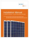
Installation Manual
for MEMC Silvantis 60 cell Photovoltaic Modules
Product List: MEMC-M235AMA, MEMC-M240AMA, MEMC-M245AMA, MEMC-M250AMA, MEMC-M255AMA,
MEMC-M240LMA, MEMC-M250LMA, MEMC-M260LMA, MEMC-M240AMC, MEMC-M245AMC, MEMC-M250AMC, MEMC-M255AMC, MEMC-M260AMC,
MEMC-M240LMC, MEMC-M250LMC, MEMC-M260LMC
© Copyright 2012 MEMC Electronic Material
Installation Manual: MEMC Silvantis 60 cell PV Modules
2 of 15
Table of Contents
1.0 INTRODUCTION.................................................................................................................................................... 3
2.0 PHOTOVOLTAIC MODULES PRODUCT CODE..................................................................................... 3
3.0 MODULE OVERVIEW........................................................................................................................................... 3
3.1 STORAGE, UNPACKING, AND HANDLING........................................................................................................... 3
3.2 SAFETY........................................................................................................................................................................ 4
3.3 MAINTENANCE.......................................................................................................................................................... 4
4.0 MECHANICAL INSTALLATION......................................................................................................................... 5
4.1 PLANNING AND DESIGN.......................................................................................................................................... 5
4.2 MODULE INSTALLATION OPTIONS........................................................................................................................ 5
4.3 MODULE INSTALLATION USING CENTER MOUNTING BRACKETS................................................................... 7
4.4 MODULE INSTALLATION USING SHARED RAILS M240/250/260LMA AND M240/250/260LMC ........ 7
4.5 MECHANICAL INSTALLATION WARNINGS............................................................................................................ 8
5.0 ELECTRICAL INSTALLATION.............................................................................................................................. 8
5.1 PLANNING AND DESIGN.......................................................................................................................................... 8
5.2 MODULE WIRING....................................................................................................................................................... 8
5.3 GROUNDING.............................................................................................................................................................. 9
5.4 ELECTRICAL INSTALLATION WARNINGS............................................................................................................. 10
6.0 DISCLAIMER OF LIABILITY.............................................................................................................................. 10
7.0 MECHANICAL AND ELECTRICAL PARAMETERS AND SPECIFICATIONS............................... 11
8.0 APPENDIX.................................................................................................................................................................. 13
8.1 MODULE DETAILS.................................................................................................................................................... 13
8.2 MODULE ILLUSTRATIONS...................................................................................................................................... 14
8.3 PRE MOUNTED CABLES AND CONNECTORS.................................................................................................... 15
Customer Service
MEMC Singapore PTE. LTD.
11 Lorong 3 Toa Payoh
Block B Jackson Square 4th Floor
Singapore 319579
Fax: (65) 6681-9301
Email: [email protected]
Website: www.sunedison.com
© Copyright 2012 MEMC Electronic Material
Installation Manual: MEMC Silvantis 60 cell PV Modules
3 of 15
1.0 Introduction
The purpose of this guide is to provide general information regarding the proper installation and handling of MEMC photovoltaic
modules that serve residential, commercial, and industrial segments. System design, construction, and commissioning should be
performed by qualified personnel only.
To ensure system integrity, designers, installers and operators must meet all mechanical and electrical requirements for the system and
its components. It is the responsibility of the system designer and installer to ensure that all codes and requirements are followed as
well.
Please review all the sections that pertain to proper installation of modules listed in this Guide. The instructions detailed in this guide
must be followed throughout the module’s lifetime deployment. If you need additional information about the safe, proper use and
handling of MEMC photovoltaic module products, please contact MEMC.
2.0 Photovoltaic Modules Product Code
This guide is to be used for MEMC Silvantis 60 cell photovoltaic (PV) module installation. Please refer to the following module numbers
before using the guide:
Modules with tempered glass: MEMC-M235AMA, MEMC-M240AMA, MEMC-M245AMA, MEMC-M250AMA, MEMC-M255AMA
Modules with anti-reflective coating (AR coating or ARC): MEMC-M240AMC, MEMC-M245AMC, MEMC-M250AMC,
MEMC-M255AMC, MEMC-M260AMC
Modules with corner cap and tempered glass: MEMC-M240LMA, MEMC-M250LMA, MEMC-M260LMA
Modules with corner cap and anti-reflective coating: MEMC-M240LMC, MEMC-M250LMC, MEMC-M260LMC
3.0 Module Overview
MEMC Silvantis Photovoltaic modules consist of a series of electrically interconnected crystalline silicon solar cells that are sealed within
a laminated sheet of tempered glass superstrate* and EVA/back-sheet substrate. These laminates are secured inside an aluminum
frame to provide rigidity and a means for attachment to mounting sub-structures. The frames should not be modified or removed.
* Tempered glass may have AR coating.
• Photovoltaic modules are designed and constructed for outdoor use. Do not submerge modules in water at any time.
• The front and back of each module is labeled with a product bar code. Do not cover, remove or deface these labels. This may
be required for product identification.
• Damage to the glass surface or the anti-reflective coating can impact the power output and overall efficiency of the system.
Scratches, handling marks, or any damage to the glass surface must be avoided.
• For best performance and to avoid potential issues, keep the front side of the module clean and free of obstructions including
covers, tape, adhesives, paint and debris.
3.1 Storage, Unpacking, and Handling
• Packaged modules must be stored in a dry and ventilated area.
• Packaged modules must not be exposed to rain, snow, hail or other environmental conditions that may compromise the
packaging material and the modules.
• Packaged modules must be on appropriate provided pallets and must not be stacked more than two pallet high for storage.
• Once the modules are opened, store modules in a dry and ventilated room.
• Modules should never be stored in a wet environment.
• Upon unpacking, do not carry a module by its wires or junction box. Only carry a module by its frame with two or more
people.
• Precaution should be taken to avoid damage to the glass surface with or without anti-reflective coating due to improper
handling during storage or unpacking.
© Copyright 2012 MEMC Electronic Material
Installation Manual: MEMC Silvantis 60 cell PV Modules
4 of 15
• Keep all electrical contacts clean and dry.
• All modules are manufactured with a sealed junction box and pre-attached cables and locking connectors. These
components should not be modified or tampered with in any way.
• Do not allow unauthorized persons near the installation site or storage area of modules.
• Do not place modules on top of one another.
• Do not place any load on the module or twist the module frame.
• Do not stand, step, walk, or jump on the module.
• Do not drop or place objects on the modules such as tools.
• Do not handle modules with bare hands and avoid scratches, handling marks, or any damage especially to the front glass of
the module, backsheet, or electrical components.
• Do not mark the modules with sharp instruments.
• Do not leave a module unsupported or unsecured.
• Do not modify module frames in any way.
3.2 Safety
The following safety guidelines and best practices should be followed:
• All installations must be performed in compliance with all applicable regional and local electrical codes or other national or
international electrical standards.
• Use insulated tools during installation, troubleshooting and maintenance of photovoltaic modules.
• Wear suitable protection to prevent direct contact with module’s electrical output and mechanical sharp edges.
• Cover the front of the modules with an opaque material to stop production of electricity when installing or working with a
module or wiring.
• Modules connected in a series should not be disconnected under illumination. Disconnecting modules under illumination may
cause electrical arcing which may result in burns, fires or other problems.
• Follow industry best practices when commissioning, trouble shooting, disconnecting, or connecting a PV system.
• Trouble shooting should include planning, checking, disconnecting, cause seeking, replacement, and record keeping.
• Do not install or handle the modules or their components when they are wet or during periods of high wind.
• Do not attempt to disassemble, repair, or open any part of the module including junction box or sub-components.
• Do not artificially concentrate sunlight on a module.
• Do not install or handle any broken modules. If a module is broken, or the back sheet is torn, contact with the surface or
frame can cause an electrical shock.
• Do not wear rings, jewelry, watches, or other metallic items while working with photovoltaic modules.eping.
3.3 Maintenance
Check modules, glass, and frames for damage. Regularly inspect all MEMC Silvantis Solar Modules for safe electrical connections,
sound mechanical connections, and freedom from shading and corrosion. If dirt or debris buildup becomes excessive, periodically
clean the glass only with a soft cloth using mild, non-abrasive detergent and water. When using mild cleaning liquids, a neutral pH in
the range of 6.0 to 8.0 is recommended. Chemicals with pH less than 6.0 or greater than 8.0 should be avoided as it may damage
the glass surface and or the AR coating. Please consult with system designer to decide the cleaning and inspection frequency
according to local environmental conditions.
Do not power wash or use harsh cleaning materials or objects such as scouring powder, steel wool, scrapers, blades, or other sharp
instruments to clean the glass surface of the module. Use of such materials will invalidate the product warranty.
WARNING: Use caution when cleaning the back surface of the module to avoid penetrating the substrate materials.
© Copyright 2012 MEMC Electronic Material
Installation Manual: MEMC Silvantis 60 cell PV Modules
5 of 15
4.0 Mechanical Installation
4.1 Planning and Design
• Before installation, check to ensure all sub-structure will accommodate expected system loads. This includes and is not
limited to roof, foundations, mechanical structure, and mechanical connections.
• For roof installations, utilize a fire-resistant roof covering rated for the application.
• Mechanical structures should not contact the module backsheet under any expected load conditions
• Consider the following factors during system design, which will influence performance:
a)
MEMC solar modules produce the most power when they are pointed directly at the sun, and should be tilted for
optimum system performance.
b) Proximity to obstructions such as: walls, buildings, trees, groundcover, snow cover, or dust and debris that have the
potential to shade or damage the modules.
c)
Elevated temperatures will decrease energy yield, so designs should ensure adequate airflow across the back of the
module.
d) Allow a minimum spacing of 10 mm between modules for thermal expansion.
4.2 MODULE INSTALLATION OPTIONS For mounting locations
For mounting locations for clamps or bolt for specified load, please refer to Table on page 6.
• Each module should be mounted using four bolts through the mounting holes on the rear side of the module, or with four
clamps over the front side.
• Depending on the desired load capability of the array, modules may be mounted either perpendicular or parallel to the
structure rails. Clamps can be mounted anywhere inside of the safe mounting range for each case illustrated below (referring
to chart showing clamp and bolt mounting locations).
• If using bolts, eight mounting holes are provided on the rear side the module frame as shown in Appendix 8.1. Use a stainless
steel bolt stack no smaller than ¼"-20 or M6, with two flat washers and a locking washer as shown in Appendix 8.2.
• To ensure an adequate clamping area, all clamps used should comply with the following general conditions:
1.
Clamp height must correspond to 50 mm frame height
2.
Clamp must have a minimum width of 38 mm
3.
Clamp depth must be between 6 mm to 10 mm
• All fasteners used to fix the modules with clamps should be stainless steel, and no smaller than ¼”-20 or M6.
• To provide adequate fixing or clamping force, torque the minimum recommended fasteners to 13.6 - 16.3 N.m [10 - 12 ft lb].
• All other structural dimensions, such as clamp and rail thickness, should be sized appropriately for the intended site load.
© Copyright 2012 MEMC Electronic Material
Installation Manual: MEMC Silvantis 60 cell PV Modules
6 of 15
4.2a mounting configurations using BOLT MOUNT OR CLAMP MOUNT OPTIONS
mOUNTING CONFIGURATIONS
Load parameters
Bolt Mount
LOCATIONS
clamp mount
locations
A
Perpendicular mounting
(cases 1 & 2)
cASE 1
Structural rails running perpendicular to
the length of the module should be fixed
via bolts or clamps at the mounting holes
between each long side frame, OR at the
holes on each short end frame.
Maximum
Rear Load:
Clamp mount
allowable range
2400 Pa or 50 psi
Maximum
Front Load:
5400 Pa or 113 psi
NOTE: All modules are rated for a
maximum rear load of 2400 Pa and a
maximum front load of 5400 Pa when
fixed to the side frames mounting holes
for CASE 1 or a front load of 2400 Pa
when fixed to the end frames mounting
holes for CASE 2.
REAR VIEW
FRONT VIEW
B
cASE 2
Maximum
Rear Load:
2400 Pa or 50 psi
Clamp mount
allowable range
Maximum
Front Load:
5400 Pa or 113 psi
REAR VIEW
Parallel mounting (case 3)
Maximum
Rear Load:
Structural rails running parallel to the length
of the module should be fixed via bolts or
clamps ONLY at the mounting holes on
each long side frame.
A
2400 Pa or 50 psi
cASE 3
NOTE: All modules are rated for a
maximum rear load of 2400 Pa and a
maximum front load of 5400 Pa when
fixed to the mounting holes on the long
side frames only.
FRONT VIEW
Clamp mount
allowable range
Maximum
Front Load:
5400 Pa or 113 psi
REAR VIEW
FRONT VIEW
Structural rails running parallel to the
length of the module should NEVER be
fixed to the end frames.
Module Color Code:
Mounting Hole Location Module Rail Clamp Mount Range
Clamp mount allowable range: A – 382 mm
B – 248 mm
© Copyright 2012 MEMC Electronic Material
Installation Manual: MEMC Silvantis 60 cell PV Modules
7 of 15
4.3 Module Installation Using Center Mounting Brackets
• Modules may also be mounted using center clamps as shown in Appendix 8.2, for use with trackers.
• Module clamps for center mounting must be based on MEMC approved extrusion and hardware.
• For module loads higher than 2400 Pa, module clamps and hardware must be pre-approved by MEMC.
4.4 Module installation using shared rails (M240/250/260LMA and M240/250/260LMC SPECIFIC)
Illustration
Step 1: Place the bottom of the module on the
approved rail at an angle, allowing the module
to toe into the rail hook as shown in figure to the
right, and lower onto the ledge of the next rail.
step 1
Installation Step
Step 2: Ensure that the rails are tight against
the modules by adjusting the upper rail.
Step 4: Tighten the included fasteners for the
clips to 11.5 Newton.meters (or 8.5 foot pounds
of torque).
step 3
Step 3: Use the module clips provided to clamp
the module to the rail at each of the two upper
corners on the module frame as shown in figure
to the right.
Toeing module into rail hook
Module clip attachment
Toe in Modules using Corner Cap Feature
System Overview
© Copyright 2012 MEMC Electronic Material
Installation Manual: MEMC Silvantis 60 cell PV Modules
8 of 15
4.5 Mechanical Installation Warnings
• Installation and maintenance should be performed by qualified personnel only.
• Use insulated tools during installation, troubleshooting and maintenance of photovoltaic modules.
• Installers should adhere to all applicable local, regional, and national codes and regulations when designing and constructing
the photovoltaic system.
• Do not stand or walk on any surface of the modules.
• Precaution should be taken to avoid damage to the glass surface with or without anti-reflective coating due to improper
handling during installation.
• Mechanical structures should not contact the module backsheet under any expected load conditions.
• Additional mounting holes may not be drilled in the frame, glass or backsheet.
• Ensure that frame weep holes (see Appendix 8.1) are not obstructed by the mechanical installation.
5.0 Electrical Installation
5.1 Planning and Design
• All modules are manufactured with a sealed junction box and pre-attached cables and locking connectors. These
components should not be modified or tampered with in any way.
Note: Installers should ensure that the polarized locking connectors are from the same supplier when connected on the
same string. We do not recommend mixing polarized interlocking connectors from different manufacturers—including
connections at the inverter, combiner boxes, and modules.
• Ensure connectors are clean and dry before establishing connection.
• Ensure that all wire, fusing and disconnects are appropriately sized for the system design according to national, regional, and
local codes.
• Electrical characteristics are within plus or minus 5% of rated values for Isc, Voc, Impp and Vmpp. Modules may operate
under conditions which may be significantly different than STC. MEMC suggests multiplying specified ratings by a minimum
of 1.25* or more when specifying the system and balance of system components. 1.25* Refer to local codes before planning
and design of the system. For detailed electrical characteristics, please refer to Section 7.0, page 10 through 11 of this
Installation Manual.
• Determine the maximum number of modules connected in series using the following formula: Ns = Vmaxs / Vocm
Where:
Ns equals the maximum modules in series
Vmaxs equals the maximum system voltage
Vmaxs is limited to a maximum of 1000 V for IEC and 600 V for UL
Vocm equals the module open circuit voltage at coldest conditions for the site (refer to local codes)
WARNING: Installers should adhere to all applicable local, regional, and national codes and regulations when designing and
constructing the photovoltaic system.
Note: In colder climates, it may be necessary to further reduce the maximum number of modules in series by using Vocm
at the minimum expected operating temperature.
5.2 Module Wiring
• The module includes wires and polarized locking connectors from the junction box on the back of the module. The wires
have sufficient length to connect to adjacent modules in either a portrait or landscape configuration. Field replacement of
connectors or cables must be avoided and it will invalidate the product warranty. Polarized locking connectors of the same
type and make are needed for all series string wiring. The maximum operating temperature of wires and connectors should
not exceed 85ºC.
© Copyright 2012 MEMC Electronic Material
Installation Manual: MEMC Silvantis 60 cell PV Modules
9 of 15
WARNING: It is not recommended to mix connectors from different suppliers within the same string. This includes
connections at the inverter, combiner boxes, and modules.
• Always wire modules so that proper polarity is maintained. Avoid placing excessive tension on the cables.
• There is no limit to the maximum number of series strings that can be combined in parallel. However, when doing so, each
string must include overcurrent protection with a maximum rating of 15A. MEMC recommends the use of DC rated fuses or
overcurrent protection devices with the appropriate maximum voltage rating.
• Do not connect modules directly to a parallel bus.
• The cross-sectional area of cable and the connector type must be selected to align with the overall system design and should
include the maximum short circuit current of the system, maximum operating temperatures, and cable run lengths.
• For field connections, use at a minimum #12 AWG/4 mm2 wires insulated for a minimum of 85°C. Use copper wire only.
5.3 Grounding
• The module frame includes several labeled grounding holes. These holes may not be used for any other purpose.
• MEMC recommends a Burndy BGBL-4 AL lay-in lug for grounding.
• Only Negative grounding circuits (negative polarity to ground) shall be used within the array design.
• Attach the grounding lug to the frame as follows:
Step 1: Use stainless steel hardware.
Step 2: Place the grounding lug over the grounding hole on the exterior of the module frame.
Step 3: Place a star washer directly between the bottom of the grounding lug and the exterior surface of the frame.
Step 4: Place an M4 or #8-32 bolt through the lug, star washer and frame grounding hole.
Step 5: Secure the lug to the frame using a flat washer, split washer and M4 or #8-32 nut.
Step 6: Torque the bolt stack to approximately 1.5 N.m (or 1.1 foot pounds) to ensure the star washer scratches the
anodized frame.
© Copyright 2012 MEMC Electronic Material
Installation Manual: MEMC Silvantis 60 cell PV Modules
10 of 15
5.4 Electrical Installation Warnings
• Installation and maintenance should be performed by qualified personnel only.
• Use insulated tools during installation, troubleshooting and maintenance of photovoltaic modules.
• Installers should adhere to all applicable local, regional, and national codes and regulations when designing and constructing
the photovoltaic system.
• Photovoltaic modules produce DC electrical energy from light. When illuminated, each module can have a DC potential of
greater than 45V and should be handled with care.
• Disconnecting modules under illumination may cause electrical arcing which may result in burns, fires, or other problems.
Modules connected in series should not be disconnected under illumination.
• Always use a wire management system that keeps wires and cables out of direct contact with edge surfaces which could cut
or damage the insulation. Do not allow wires to rest on the ground or roof surface.
• The module junction box should not be opened or modified in any way in the field.
• Additional grounding holes may be added only with the express written consent of MEMC. New grounding holes must be
drilled using an approved drill jig, avoiding damage to the module glass, backsheet, or other module components.
• Do not use mirrors, lenses, or other techniques to magnify or concentrate additional light on the module.
6.0 Disclaimer of Liability
The information in this manual is based on MEMC’s knowledge and experience and is believed to be accurate. However, all
information in this manual (without exception) including recommendations and specifications does not constitute a warranty,
expressed or implied. MEMC reserves the right to change the manual, the module, or specifications without prior notice.
The product warranty shall be VOID if handling and installation of the product does not conform to MEMC’s written installation
instructions, or if the product has been reworked, repaired or otherwise modified in a manner not previously authorized by MEMC in
writing, or if the product is installed in an environment for which it was not designed. MEMC shall not be liable for special, indirect,
consequential, contingent or incidental damages related to or arising from the installation or use of the product by purchaser under
any circumstances.
MEMC assumes no responsibility for any product application or use which is beyond MEMC’s direct control. MEMC does not accept
responsibility and expressly disclaims liability for loss, damage, or expense arising out of or in any way connected to such installation,
operation or maintenance of the product.
International Product Certifications:
IEC 61215, IEC61730, CE, UL 1730, and Safety Class II certifications ensure that MEMC solar products operate safely and comply with
global electrical, performance, reliability, and fire safety codes.
• IEC61215 certified by TÜV SÜD to ensure long-term operation in a variety of climates
• IEC61730 certified by TÜV SÜD to ensure electrical safety
Certification
• Stringent outgoing quality acceptance criteria benchmarked to industry standards
• UL1703 listed by CSA for Canada and US
Environmental
AB8 (-50°C to +40°C)
Fire Resistance Rating
Class C
MEMC Modules are certified by:
© Copyright 2012 MEMC Electronic Material
Installation Manual: MEMC Silvantis 60 cell PV Modules
11 of 15
7.0 Mechanical and Electrical Parameters and Specifications
Modules with corner cap and tempered glass:
MEMC-M240/250/260LMA
Modules with tempered glass:
MEMC-M235/240/245/250/255AMA
PHYSICAL PARAMETERS
PHYSICAL PARAMETERS
Module Dimensions (mm)
Module Weight (kg)
1,658 x 990 x 50
Cell-Type
Mono-crystalline
60
19
Number of Cells
Frame Material
Glass (mm)
46±2
-0.47 to -0.49
-0.35
Mono-crystalline
60
Black Anodized Aluminum
Black Anodized Aluminum
3.2 Tempered Glass
TEMPERATURE COEFFICIENTS AND PARAMETERS*
Nominal Operating Cell Temperature (NOCT) (°C)
Temperature Coefficient of Pmax ( %/°C)*
Temperature Coefficient of Voc ( %/°C)*
Temperature Coefficient of Isc ( %/°C)*
+0.036 to +0.055
-40 to +85
46±2
-0.47 to -0.49
-0.35
+0.036 to +0.055
-40 to +85
8.40
Operating Temperature (°C)
Maximum System Voltage (V)
Limiting Reverse Current (A)
8.40
15
Maximum Series Fuse Rating (A)
15
600 (UL) & 1000 (IEC)
Maximum System Voltage (V)
Limiting Reverse Current (A)
Maximum Series Fuse Rating (A)
Cell-Type
Corner Caps
Glass (mm)
TEMPERATURE COEFFICIENTS AND PARAMETERS*
Temperature Coefficient of Pmax ( %/°C)*
Temperature Coefficient of Voc ( %/°C)*
Temperature Coefficient of Isc ( %/°C)*
Operating Temperature (°C)
1,674 x 1,006 x 50
19.3
Number of Cells
Frame Material
Anodized Aluminum
3.2 Tempered Glass
Nominal Operating Cell Temperature (NOCT) (°C)
Module Dimensions (mm)
Module Weight (kg)
600 (UL) & 1000 (IEC)
Temperature coefficients may vary by ± 10%
Temperature coefficients may vary by ± 10%
*Refer 240W solar module and MEMC Silvantis 250W module data sheets for specific
temperature coefficients
*Refer 240W solar module and MEMC Silvantis 250W module data sheets for specific
temperature coefficients
MEMCM235AMA
MEMCMEMCMEMCM240AMA M245AMA M250AMA
MEMCM255AMA
Rated Maximum Power Pmax (W)
Open-Circuit Voltage Voc (V)
Short Circuit Current Isc (A)
Module Efficiency (%)
235
240
37.4
245
37.5
250
37.6
255
37.8
8.70
14.6
8.80
14.9
8.90
15.2
9.00
15.5
Maximum Power Point Voltage Vmpp (V)
Maximum Power Point Current I mpp (A)
Power Range (W)
29.3
8.03
29.5
8.15
29.7
8.25
29.9
8.36
30.0
8.50
-0/+5
-0/+5
-0/+5
-0/+5
-0/+5
Model #
37.3
8.60
14.3
Modules with corner caps
ELECTRICAL CHARACTERISTICS *
MEMCM240LMA
MEMCM250LMA
MEMCM260LMA
240
37.4
250
37.6
260
38.0
8.70
14.6
8.90
15.2
9.10
15.8
29.5
8.15
29.9
8.36
30.1
8.64
±6
-4/+5
±5
All electrical data at STC: 1000W/m2, AM1.5, 25ºC
Electrical characteristics may vary by ±5%
* Listed specifications are subject to change without prior notice.
© Copyright 2012 MEMC Electronic Material
Installation Manual: MEMC Silvantis 60 cell PV Modules
12 of 15
7.0 Mechanical and Electrical Parameters and Specifications
Modules with corner cap and anti-reflective coating:
MEMC-M240/250/260LMC
Modules with anti-reflective coating:
MEMC-M240/245/250/255/260AMC
PHYSICAL PARAMETERS
PHYSICAL PARAMETERS
Module Dimensions (mm)
Module Weight (kg)
1,658 x 990 x 50
Cell-Type
Mono-crystalline
60
19
Number of Cells
Frame Material
Glass (mm)
46±2
-0.49
-0.35
Mono-crystalline
60
Black Anodized Aluminum
Black Anodized Aluminum
3.2 Tempered ARC glass
TEMPERATURE COEFFICIENTS AND PARAMETERS*
46 ±2
Nominal Operating Cell Temperature (NOCT) (°C)
Temperature Coefficient of Pmax ( %/°C)
Temperature Coefficient of Voc ( %/°C)
Temperature Coefficient of Isc ( %/°C)
+0.055
-40 to +85
-0.49
-0.35
+0.055
-40 to +85
Operating Temperature (°C)
Maximum System Voltage (V)
Limiting Reverse Current (A)
600 (UL) & 1000 (IEC)
Maximum System Voltage (V)
Limiting Reverse Current (A)
Maximum Series Fuse Rating (A)
Cell-Type
Corner Caps
Glass (mm)
TEMPERATURE COEFFICIENTS AND PARAMETERS*
Temperature Coefficient of Pmax ( %/°C)
Temperature Coefficient of Voc ( %/°C)
Temperature Coefficient of Isc ( %/°C)
Operating Temperature (°C)
1,674 x 1,006 x 50
19.3
Number of Cells
Frame Material
Anodized Aluminum
3.2 Tempered ARC glass
Nominal Operating Cell Temperature (NOCT) (°C)
Module Dimensions (mm)
Module Weight (kg)
8.40
600 (UL) & 1000 (IEC)
8.40
15
Maximum Series Fuse Rating (A)
15
Temperature coefficients may vary by ± 10%
Temperature coefficients may vary by ± 10%
Model #
Rated Maximum Power Pmax (W)
Open-Circuit Voltage Voc (V)
Short Circuit Current Isc (A)
Module Efficiency (%)
Maximum Power Point Voltage Vmpp (V)
Maximum Power Point Current I mpp (A)
Power Range (W)
MEMCM240AMC
MEMCM245AMC
MEMCMEMCM250AMC M255AMC
MEMCM260AMC
240
37.6
245
37.7
250
37.8
255
37.9
260
40.0
8.80
14.6
8.90
14.9
9.00
15.2
9.10
15.5
9.20
15.8
29.0
8.37
29.2
8.47
29.4
8.57
29.6
8.67
29.8
8.77
-0/+5
-0/+5
-0/+5
-0/+5
-0/+5
Modules with corner caps
ELECTRICAL CHARACTERISTICS *
MEMCM240LMC
MEMCM250LMC
MEMCM260LMC
240
37.6
250
37.8
260
40.0
8.80
14.6
9.00
15.3
9.20
15.8
29.0
8.37
29.4
8.57
29.8
8.77
-6/+6
-4/+5
-5/+5
All electrical data at STC: 1000W/m2, AM1.5, 25ºC
Electrical characteristics may vary by ±5%
* Listed specifications are subject to change without prior notice.
IV CURVES AT MULTIPLE IRRADIANCES* [25°C]
IV CURVES AT MULTIPLE TEMPERATURES* [1000 W/m 2]
9
10
8
8
7
Current (A)
Current (A)
6
5
4
6
4
3
2
2
1
0
0
5
10
15
20
25
30
35
40
0
0
5
Voltage (V)
10
15
20
25
30
35
40
Voltage (V)
25°C
1000 W/m2
800 W/m2
400 W/m2
45°C
600 W/m2
200 W/m2
60°C
© Copyright 2012 MEMC Electronic Material
Installation Manual: MEMC Silvantis 60 cell PV Modules
13 of 15
8.0 Appendix
8.1 Module dETAILS
Dimension
MM
INCH
Dimension
Module Dimensions
MM
INCH
Mounting Hole Spacing
Dimension
MM
INCH
Cable Length for AMA and AMC
A
990
39.0
E
940
37.0
B
1,658
65.3
F
1,608
63.3
Cable Length for ACA and ACC
C
50
2.0
G
994
39.1
L
D
40
1.6
H
594
23.4
L
1,000
1,300
39.4
51.2
© Copyright 2012 MEMC Electronic Material
Installation Manual: MEMC Silvantis 60 cell PV Modules
14 of 15
8.0 Appendix
8.1A Module dETAILS (M240/250/260LMA and M240/250/260LMC SPECIFIC) — dimensions: [inch] mm
Front View
Side View
8.2 Module illustrations
Center Mount Option
Bolt Stack Details
© Copyright 2012 MEMC Electronic Material
Installation Manual: MEMC Silvantis 60 cell PV Modules
15 of 15
8.0 AppendiX
8.3 Pre-mounted Cables and connectors
Mounting Configuration
Pre-mounted cables
Pre-mounted connectors
Type
TUV – PV1-F & UL – PV wire
locking polarized connectors
Cross section
4.0 mm²
4 mm dia.
Max. current
16 A
25 A
Max. system voltage
1000 VDC/ UL 600 V
1000 VDC/ UL 600 V
Temperature rating
-40°C to +90°C
-40°C to +85°C
Qualification
TUV 2PFG & UL PV wire
EN 50521 & UL for PV sys
© Copyright 2012 MEMC Electronic Material Controlled Document - MEMC Electronic Materials, Inc. Void if Printed or Electronically
Duplicated. Information contained herein may not be revealed or disclosed to unauthorized persons or sent outside MEMC without prior
authorization. Match printed version to documentation database.
MEMC Electronic Materials, Inc. 501 Pearl Drive (City of O’Fallon) St. Peters, MO 63376 USA | 1-636-474-5000 | www.sunedison.com |
60-Cell Install Manual Q2_2012
© Copyright 2012 MEMC Electronic Material