1
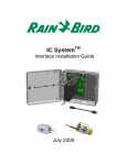
IC System TM ICMR Relay Installation Guide August 2015 IMPORTANT NOTES: INSTALLING THE ICMR – Integrated Control Relay Device ...... 3 Compliance Information .................................................................................................. 4 Installation Checklist........................................................................................................ 5 Verify Contents of the Packing Box ................................................................................. 6 Choose Location to Install the ICMR ............................................................................... 6 Gather Installation Tools ................................................................................................. 7 Connect IC SystemTM Field Wiring .................................................................................. 8 Connect Relay Source and Output .................................................................................. 9 Safely Terminate Any Unused Relay Connections ........................................................ 11 Complete Installation ..................................................................................................... 12 Configure Rain Bird Central Control Software ............................................................... 13 Configure General-Purpose Electrical Outputs ............................................................. 16 Configure Booster Pump Control .................................................................................. 21 2 ICMR Installation Guide IMPORTANT NOTES: INSTALLING THE ICMR – Integrated Control Relay Device This section explains how to install and configure the ICMR device. NOTE: The ICMR device must be installed in compliance with all electrical codes and, when used with voltages above 40VDC, must be installed indoors. NOTE: The installation of the ICMR device should be performed with the IC SystemTM wire path unpowered. NOTE: For the first two minutes after the wire path has been reactivated, there will not be any operation or response from the field ICMR devices. WARNING: Field wire paths must be kept separate from other wire paths. Do not connect the field wires together from different output (group) wire paths on the ICI - Integrated Control Interface WARNING: This appliance is not intended for use by persons (including children) with reduced physical, sensory or mental capabilities, or lack of experience and knowledge, unless they have been given supervision or instruction concerning use of the appliance by a person responsible for their safety. WARNING: Children should be supervised to ensure that they do not play with the appliance. ICMR Installation Guide 3 Compliance Information E41049 This device complies with Part 15 of the FCC rules subject to the following two conditions: (1) This device may not cause harmful interference, and (2) This device must accept any interference received, including interference that may cause undesired operation. This Class B digital apparatus meets all requirements of the Canadian Interference Causing Equipment Regulations. EN61000-6-1 (1997) Class B: EN61000-3-2 EN61000-3-3 EN61000-6-3 (1996): EN61000-4-2 EN61000-4-3 EN61000-4-4 EN61000-4-5 EN61000-4-6 EN61000-4-8 EN61000-4-11 EN 60335-1: 2010 Safety of household and similar electrical appliances 4 ICMR Installation Guide Installation Checklist The following steps are recommended in order to properly install the ICMR device. For your convenience, a check-off box has been provided for each step. Verify the contents of the packing box. Choose a location to install the ICMR. For low-voltage applications the device may be installed in a valve box, provided that local electrical code allows it. For high-voltage applications, indoor installation is required. Gather installation tools Connect IC SystemTM field wiring Connect relay source and output Safely terminate any unused ICMR connections Complete the installation Configure Rain Bird central control software ICMR Installation Guide 5 Verify Contents of the Packing Box ICMR Device Choose Location to Install the ICMR Choose a location minimizing wiring length between ICMR and relay source and output connections. Choose a location with easy access to the IC SystemTM wire path. NOTE: This controller must be installed in compliance with all electrical codes. 6 ICMR Installation Guide Gather Installation Tools Wire strippers Rain Bird DBRY splice kits (5 total splices) ICMR Installation Guide 7 Connect IC SystemTM Field Wiring 1. The ICMR device should arrive from the factory with wire ends stripped. If not, strip approximately 1” of insulation from each wire. Take care not to score the copper strands. 2. Strip approximately 1” of insulation from each MAXI® wire (IC SystemTM field wiring) to be spliced with ICMR. Take care not to score copper conductor. 3. Connect the ICMR (red) wire to the MAXI® (red) wire. Do not connect the ICMR (red-with-white-stripe) wire at this step. The ICMR-MAXI® connection should be solid red. 4. Connect the ICMR (black) wire to the MAXI® (black) wire. Do not connect the ICMR (black-with-white-stripe) wire at this step. The ICMR-MAXI® connection should be solid black. 5. Add suitable protection to the splices. For installation in a valve box, use a Rain Bird DBRY splice kit for each splice, securing the splice with the wire nut then inserting the splice completely into the grease cap. Note that grease caps are single-use; do not attempt to reuse them. 8 ICMR Installation Guide Connect Relay Source and Output The ICMR device switches an input voltage, connected to the ICMR (white) RELAY COMMON wire based on IC SystemTM commands received from the central control PC. When the ICMR station is OFF, RELAY COMMON is connected to the ICMR (red-withwhite-stripe) RELAY N/C (NORMALLY CLOSED) output wire. When the ICMR station is ON, RELAY COMMON is connected to the ICMR (black-with-white-stripe) RELAY N/O (NORMALLY OPEN) output wire. NOTE: During installation of the ICMR device and prior to powering on the IC SystemTM wire path, RELAY COMMON may be connected internally to either RELAY N/C or RELAY N/O. If an external source voltage is applied to RELAY COMMON, it will be presented to either RELAY N/C or RELAY N/O. After the IC SystemTM wire path has been powered for two (2) minutes, the ICMR will be placed in the OFF state, with RELAY COMMON connected internally to RELAY N/C. Take care against touching any ICMR wires when any inputs or outputs are connected to live signals. Isolate the ICMR before installation or service. . CAUTION: All electrical wiring connections and wiring runs must be made according to local building codes. ICMR Installation Guide 9 The drawing below shows a typical ICMR application for booster pump control. The RELAY COMMON input is connected to a suitable control voltage for the pump starter coil (or a suitable voltage for a pump start relay). This is typically a low-voltage source, rather than wall power, for safety. The RELAY N/O output is used. When the ICMR is OFF, the output is not energized keeping the pump/pump relay OFF, also. When the ICMR is ON, the control voltage from RELAY COMMON is connected to RELAY N/O and to the pump coil or pump start relay, triggering the pump. AC Power 240/480VAC Power ICMR Starter Coil 1. The ICMR device should arrive from the factory with wire ends stripped. If not, strip approximately 1” of insulation from each wire. Take care not to score the copper strands. 2. Strip approximately 1” of insulation from each external connection wire to be spliced with ICMR. Take care not to score copper conductors. 3. Connect ICMR (white) wire to input source connection for relay. 10 ICMR Installation Guide 4. Based on application, connect either or both ICMR outputs, ICMR (red-withwhite-stripe) RELAY N/C and ICMR (black-with-white-stripe) RELAY N/O to appropriate field wiring. 5. Add suitable protection to the splices. For installation in a valve box, use a Rain Bird DBRY splice kit for each splice, securing the splice with the wire nut then inserting the splice completely into the grease cap. Note that grease caps are single-use; do not attempt to reuse them. In all cases follow local electrical codes. Safely Terminate Any Unused Relay Connections 1. If either ICMR output, ICMR (red-withwhite-stripe) RELAY N/C or ICMR (black-with-white-stripe) RELAY N/O, is unused in application, make sure to isolate the unused wire using a Rain Bird DBRY splice kit. Secure the stripped wire end in the wire nut and insert the assembly completely into the grease cap. Note that grease caps are single-use; do not attempt to reuse them. In all cases follow local electrical codes. ICMR Installation Guide 11 Complete Installation 1. Double-check safety of all connections. Assure that all electrical codes have been followed and that no exposed wire ends are present. Take particular care with the RELAY N/C and RELAY N/O connections, as these will be live when the ICMR is OFF or ON. 2. Assure that ICMR and the connections are suitably protected from surrounding environment. 3. Note the ICMR address from the barcode label (or use the tear-off copy of the label) for entry into Rain Bird central control software. 4. Apply power to the IC SystemTM wire path. Allow two (2) minutes for all IC SystemTM devices on the wire path to power-up before performing operations. After two (2) minutes, the ICMR will be in the OFF state, with RELAY COMMON connected internally to RELAY N/C. 5. Apply external signal to RELAY COMMON (RELAY N/C will immediately be exposed to this signal also as the relay is OFF). 12 ICMR Installation Guide Configure Rain Bird Central Control Software 1. Launch Rain Bird Central Control software and select System Settings to check ICI configuration: ICMR Installation Guide 13 2. Verify that the System Settings dialog box shows a configured ICI interface (as shown below; the port number and box number are not critical but the ICI should be selected with a checkmark and the port should not be “Demo”): If no ICI is configured, refer to the IC SystemTM Installation instructions to complete this step. 3. There are two classes of relay controls you may wish to add to Rain Bird central control: general purpose electrical outputs and booster pump controls. Separate sections below describe configuration and operation of each 14 ICMR Installation Guide device class. General purpose electrical outputs might be used to control landscape lighting, water features, or other time and/or manually controlled electrical devices. Booster pump outputs are used to supply water to a section of the hydraulic system under Flow Manager control in response to irrigation requirements. 4. Apply external signal to RELAY COMMON (RELAY N/C will immediately be exposed to this signal also as the relay is OFF). ICMR Installation Guide 15 Configure General-Purpose Electrical Outputs 1. General purpose electrical outputs are configured identically to normal irrigation stations. Rain Bird recommends, however, that electrical stations be separated from hydraulic stations simplifying flow management in which electrical devices do not participate. To create a new general-purpose electrical output station, select Station Detail: 16 ICMR Installation Guide 2. In the Station Detail window shown below, select the Course, Hole and Area used for general purpose electrical devices in your system (the example shows Miscellaneous area used for such devices): 3. Create a new station in the selected area by clicking the + toobar button. The empty new station entry is shown below: ICMR Installation Guide 17 4. Select the ICI wire path where the ICMR is connected and enter the ICMR address noted from the barcode label. In the example below, the ICMR is connected to wire path 1 and its address is 0B156E: 5. Close the Station Detail window after adding the ICMR device to establish connection with the device and prepare for operation. This step matches adding a new ICM station to the system. 18 ICMR Installation Guide 6. Once the station connection is completed, the new general purpose station can be used referring to its identifier, 19M1 in the example, in a program or in manual operations. The example program below shows a “Water Feature” program controlling an ICMR set to enable the water feature during open hours for the club: In this case, the program is set to runtime of 361 minutes, six hours, running twice during the day for a total of twelve hours. Note that in actual operation, run time or start time should be adjusted to avoid a glitch between the first and second scheduled runs, as shown. When the station switches ON, relay ICMR Installation Guide 19 connection will be made between RELAY COMMON (white) and RELAY N/O (black/white). This wire would be connected to the water feature power input or control relay. 20 ICMR Installation Guide Configure Booster Pump Control 1. Booster pump control stations are created using the same steps as general purpose electrical outputs. Follow steps 1 thought 5 in section Configure General-Purpose Electrical Outputs above creating a new station, 19M2, referencing the ICMR for booster pump control. 2. The next step in configuring booster pump control is creating a booster pump station properly positioned in the FloManager hydraulic diagram. Open FloManager: ICMR Installation Guide 21 3. Determine the correct hydraulic location for the booster pump and add the pump. A simple example is shown below: 4. Open Branch Properties for the booster pump by selecting the booster pump, right-clicking, and choosing Properties: 22 ICMR Installation Guide 5. Associate the booster pump station, 19M2, to the booster pump by clicking the button: ICMR Installation Guide 23 6. Choose the booster pump station using the Course, Hole, and Station controls: 7. Attach the Booster Pump attribute to the ICMR station in Station Detail as shown below, after scrolling the Station Detail columns to the left: 8. Close Station Detail. Now that the Booster Pump attribute is set, any 24 ICMR Installation Guide FloZone irrigation in the hydraulic diagram under the booster pump will activate the booster pump station. The Booster Pump attribute ignores flow and electrical limits assigned to normal stations for the booster pump station itself. ICMR Installation Guide 25 ICMR Specifications: Operating Temperature: 14ºF to 125ºF (-10ºC to 51ºC) Storage Temperature: -40ºF to 150ºF (-40ºC to 65.5ºC) Operating Humidity: 75% max at 40ºF to 108ºF (4.4ºC to 42.2ºC) Storage Humidity: 75% max at 40ºF to 108ºF (4.4ºC to 42.2ºC) Switching Limits Voltage Current IC SystemTM Field Wiring Voltage 26 230VAC/VDC (maximum) 10VAC/VDC (minimum) 10A (@230VAC) (maximum) 100mA (@10VAC/VDC) (minimum) 26-28 VAC (max) ICMR Installation Guide