1
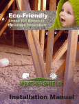
Eco-Friendly
EnviroShield
Dense-Pack Wall System
EnviroShield
Installation Manual
Enviroshield is ia dense-pack cellulose insulation
system that is ntended for application in walls,
ceilings and floors behind mesh or poly utilizing
Weathershield or ProCell Green insulation.
Cellulose insulation
provides seamless
coverage
Cellulose insulation is not only a natural choice for the environmentallyconscious consumer but one that outperforms both thermally and acoustically. With a superior R-value of 3.8 per inch, EnviroShield provides excellent coverage, perfect fit and greater density and is a sound alternative to other fibrous
insulations.
Our insulation delivers long-term fire retardant protection and unlike other
insulation products, will not melt or propagate fire. Safe and easy to install, it
does not itch or contain any formaldehyde or harmful emissions. It is specially
treated to repel insects and rodents and will not promote the growth of harmful
mold and fungi.
EnviroShield
Contact us today for more iinformation.
Dense-Pack Wall System
EnviroShield CCMC #12420-R
Masterformat #07212
EnviroShield is available coast to coast.
EnviroShield Coverage Chart / Charte de recouvrement - Walls / Murs
Walls - EnviroShield
Les calculations de recouvrement sont basés sur un sac de 11,3 KG ou 25 LBS.
www.thermocell.com
Pour de nouvelle construction, la pose doit être faite par un installeur agréé selon le système EnviroShield. Le recouvrement est selon la
Weathershield
and
ProCell Greenl are manufactured in accordance with
construction de 16" (406 mm) au centre. (Rapport D'Évaluation CCMC #12420R).
CAN/ULC-S703-09 “Standard for Cellulose Fibre insulation for Buildings”
and have been evaluated by Canadian Construction Materials Centre
(CCMC #08251-L).Coverage table values are based on 11.3 KG / 25 LBS nominal bag weight.
Versatile
Easy & Safe to install
Increased Fire Resistance
The insulation used in the EnviroShield wall system is manufactured under a
certified
quality
management
If you
all of
the
The insulation
used in
the EnviroShield
wall systemsystem.
is manufactured
underconsider
a certified quality
management
system. If you consider all of the
environmental
advantages of advantages
cellulose insulationof
and
combine thisinsulation
with its performance,
safety and cost
effectiveness,
cellulose is the right choice ... naturally.
environmental
cellulose
and combine
this
with its performance, safety and cost effectiveness, cellulose is the right choice ... naturally.
Environmentally
Preferred 87% Recycled Content
www.thermocell.com
WALLS / MUR
Thermal Resistance
Framing (Wood)
Mass per Unit Area
Coverage per Bag
# Bags Required
Résistance Thermique
Ossature (Bois)
Masse par Unité de Surface Recouvrement par Sac
Quantité de Sacs Requis
2
lb/ft2 (lb/pi2)
m2
ft2 (pi2)
100 m2 1000 ft2 (pi2)
kg/m
RSI Value
R Value
mm
in (po)
2.3
12.8
38 x 89
2x4
3.7
0.8
3.1
31.3
32.6
32.0
3.6
20.2
38 x 140
2x6
5.9
1.2
1.9
20.8
52.0
48.0
For new construction, insulation must be installed by certified installers in accordance with the EnviroShield System. Coverages are based on 16
inch (406 mm) centre construction. (CCMC Material Evaluation Report #12420R).
www.thermocell.com
With over 87% recycled content, and many performance benefits, cellulose is a
natural choice for all your insulation needs. Start saving today, save on product
cost and get immediate rewards in energy savings.
Superior thermal
and acoustical
properties - comfort
www.thermocell.com
EnviroShield Wall System Insulation
ENVIROSHIELD LOOSE FILL INSULATION
APPLICATION MANUAL
Wall System
ADVANTAGES AND BENEFITS:
•
•
•
•
•
•
•
•
•
High Stable R-Value
Controls air Leakage and Convection
Reduces Conduction
Prevents Formation of Condensation Moisture
Cooler Summers
Seamless Blanket Cover
High Density To Resist Air Movement
Sound Deadening Ability
Lasts The Lifetime of the Building
Manufactured By:
Head Office
Maritime Division
123 Clement Street1822 Plains Road
Vars, OntarioDebert, Nova Scotia
K0A 3H0B0M 1G0
(613) 443-5100(902) 662-3600
EnviroShield
TABLE OF CONTENTS
1.0
General...............................................................................................................................................1
2.0
Approvals...........................................................................................................................................1
3.0
Standards...........................................................................................................................................1
4.0
Installer Requirements......................................................................................................................1
4.1
General..................................................................................................................................1
4.2
Certification..........................................................................................................................2
5.0
Materials.............................................................................................................................................2
5.1
Insulation..............................................................................................................................2
5.2
Retaining Membrane............................................................................................................2
5.2.1 Vapour Barrier Film.................................................................................................2
5.2.2 Netting......................................................................................................................2
5.3
Vapour Barrier Patch...........................................................................................................3
5.4
Air Flow Vents......................................................................................................................3
5.5
Drywall Shims.......................................................................................................................3
6.0
Blowing Equipment...........................................................................................................................3
6.1
Equipment.............................................................................................................................3
6.2
Inspection.............................................................................................................................3
6.3
Calibration............................................................................................................................3
6.4
Field Calibration...................................................................................................................3
6.5
Equipment Maintenance......................................................................................................4
7.0
Pre-Installation Procedures..............................................................................................................4
7.1Precaution.............................................................................................................................4
7.2
Bag Usage.............................................................................................................................4
7.3
Wall Preparation...................................................................................................................4
7.3.1 Above Grade............................................................................................................4
7.3.2 Below Grade............................................................................................................4
7.4
Sloped or Cathedral Ceiling Ventilation.............................................................................5
8.0
Installation Procedures.....................................................................................................................5
8.1
Retaining Membrane............................................................................................................5
8.1.1 Vapour Barrier - Wood Frame Construction.........................................................5
8.1.1.1 Drywall Shim Fastening Method............................................................................6
8.1.1.2 Furring/Resilient Fastening Method......................................................................6
8.1.2 Vapour Barrier - Steel Frame Construction..........................................................6
8.1.2.1 Drywall Shim Fastening Method...............................................................7
8.1.2.2 Furring/Resilient Channel Fastening Method.........................................7
8.1.3 Netting - Wood Frame Construction.....................................................................7
EnviroShield
8.1.3.1 Direct Method.............................................................................................8
8.1.3.2 Furring/Resilient Channel Method...........................................................8
8.1.4 Netting - Steel Construction .................................................................................8
8.2
Filling Procedure .................................................................................................................8
8.2.1 General.....................................................................................................................8
8.2.2 Walls (Above and Below Grade)............................................................................8
8.2.3 Sloped or Cathedral Ceilings.................................................................................9
9.0
Post Installation Procedures............................................................................................................9
10.0
Quality Control................................................................................................................................10
10.1 Pre-Inspection ...................................................................................................................10
10.2 Density Verification............................................................................................................10
10.3 Quality Monitoring.............................................................................................................11
10.4 Post Inspection..................................................................................................................11
10.5 Information Cards..............................................................................................................11
10.6 Trouble Shooting................................................................................................................11
11.0
Areas of Application........................................................................................................................12
12.0
Cautions and Limitations...............................................................................................................12
12.1 General................................................................................................................................12
12.2 Below Grade.......................................................................................................................13
13.0
Warranty...........................................................................................................................................13
Appendix A - CAN/ULC S703-09 Standard
Appendix B - Coverage Chart
Products utilized for EnviroShield are
manufactured in Canada and are available
coast to coast.
EnviroShield
1.0 General
The Enviro-Shield Insulation System provides a unique and controlled way to insulate new buildings with loose-fill cellulose insulation. The system not only describes how to prepare and insulate assemblies but also defines and lists suitable materials and equipment.
The benefits of insulating buildings with loose-fill cellulose insulation is that it provides the end
user with a product offering superior thermal and acoustical resistance properties. These properties are achieved by the products ability to resist heat losses due to air infiltration and convection.
The reduction in losses are achieved because the insulation makes contact with all cavity surfaces, can conform around fixtures, plumbing and wiring and is compressed to a density higher
than conventional batt type insulations.
2.0
Approvals
2.1Insulation
Debert Facility:
CCMC Listing # 08251
Vars (Ottawa) Facility:
2.2
Insulating system 3.0
Standards
3.1
Insulation CAN/ULC-S703-09
3.2
Vapour Barrier
CAN/CGSB 51.34-M86
3.3
Insulating System 4.0
Installer Requirements
4.1
General - Installers must conduct all installations in accordance with the manual. The installer should carefully read this manual and become familiar with system principles, installation
and quality control procedures prior to installing insulation. Any individual may install insulation
under the Enviro-Shield System provided they have been certified by Thermo-Cell or are acting
under the guidance of a certified instructor or installer.
CCMC listing # 08251
CCMC Report # 12420
CCMC Masterformat 07215.5 1
4.2
Certification - Installers seeking certification must successfully complete a training program by
a designated certified instructor for all application types (e.g. standard wood frame, steel stud,
cathedral ceilings, etc.). The installer shall be thoroughly instructed on system principles,
installation and quality control procedures for all application types in order to ensure the
insulation is installed to its proper density.
Upon successful completion of the training program certified installers will be issued a
certification card.
5.0
Materials
5.1
Insulation - The system has been designed to be used exclusively with Weathershield/ProCell
Insulation manufactured by Thermo-Cell Industries Limited.
5.2
Retaining Membrane - Both 6 mil CGSB polyethylene vapour barrier and spun polypropylene
netting are suitable membranes in which to install the insulation behind. The following sections
discuss in more detail usage and limitations more fully and describe various methods and
materials suitable to securely fasten the membrane to the face of framing members.
5.2.1
Vapour Barrier Film - The vapour barrier system is designed to eliminate the need to apply
both a mesh and a vapour barrier to the exterior wall. However, its installation requires more skill
since loosely fitting poly will stretch and bulge to a greater extent. Cavities with excessive bulge
will in turn make drywall installation more difficult .The use of this vapour barrier film is suitable
for use on standard wood and steel frame construction. It can be secured to the wall using either
drywall shims, resilient channels or wood or steel furring.
The use vapour barrier membranes with the drywall shim fastening method is limited for use on
standard 400 mm (16”) centre wood or steel frame construction due to the inability of the vapour
barrier to resist excessive bulging at greater framing member spacing. If framing member are
spaced greater than 400 mm (16”) the use of wood or steel furring must be employed.
2
5.2.2
Netting - The use of netting to insulate cavities has the advantages of being easier to install,
does not required drywall shims and allows a wall to be insulated in a shorter period of time.
Netting is suitable for use on standard wood or steel frame construction having framing members
spaced up to 600 mm (24”) centres. For wood framed walls with framing members spaced up
to 24” O.C. centre and cathedral ceilings with framing member spaced no more than 16” O.C
the netting can be fastened directly to the framing members with standard 13 mm (2”) staples.
Netting for all other applications should be fastened the framing members with either resilient
channels or wood furring.
5.3
Vapour Barrier Patch - Either 6 mil CGSB polyethylene film used in conjunction with acoustical
caulking or sheathing tape approved by Thermo-Cell is suitable to repair pierced vapour barrier.
5.4
Air Flow Vents - Cardboard or polystyrene air flow vents approved by Thermo-Cell are required
to provide adequate ventilation in sloped or cathedral ceiling applications.
5.5
Plastic Strapping - 16 mm wide (5/8@) polyester (PET) plastic strapping can be used for various wood and steel frame applications to fasten vapour barrier retaining membrane to structural
members.
6.0
Blowing Equipment
6.1
Equipment - The EnviroShield system can be used with any commercially available blowing
equipment provided it has suitable air flow and material feed controls and is in good working
order. However, it is recommended that you consult with a Thermo-Cell representative on
determining the suitability of your equipment.
Blowing equipment should be equipped with 23 to 45 metres (75’ to 150’) of hose. The hose may
be comprised of either 44 mm (2”), 64 mm (2 2”) or 76.2 mm (3”) diameter hose or any
combination thereof. When installing insulation directly behind vapour barrier it is recommenced
that a membrane piercing nozzle be used on the end of the hose.
6.2
Inspection - Ensure the blowing equipment is in good working order and has no missing, broken
or worn parts.
6.3
Calibration - Calibrations are based on the type of membrane, length(s) and diameter(s) of the
hose, type of framing, framing member spacing and depth. Calibrations should be performed
with a filled hopper and maintained at a full level throughout the calibration test. Equipment supplied by Thermo-Cell has been pre-calibrated. All other equipment will have to be field calibrated.
6.4
Field Calibration - The initial field calibration step will be to roughly adjust the feed gate and air
settings. As a general rule the feed gate should be set to deliver material at a rate of 400 - 450
kg (875 - 1000 lb) per hour for solid wood frame vapour barrier configurations and depending on
the capability of the equipment 510 - 680 kg (1125 - 1500 lb) per hour for all other configurations.
The air should then be adjusted such that the hose can be blocked with a reasonable amount of
force (1 kg (2 .2 lb) pressure).
Test cavities should be prepared and blown according to section 7.0 and 8.0. The air and/or feed
gate settings should then be adjusted such that a target installed density of 48 kg/m3 (3.00 p.c.f.)
or 45 kg/m 3 (2.8 lb/ft 3) can be consistently achieved throughout the test wall or ceiling assembly
respectively. To verify the target density use procedure 10.2 ADensity verification@.
The calibration settings, hose specification, motor speed (if applicable), membrane type and
type of framing should then be recorded and placed in the manual (See Appendix B).
6.5
Equipment Maintenance - Equipment maintenance shall be the responsibility of the licensee. If
deemed necessary, equipment may be subject to periodic checkups by a qualified Thermo-Cell
employee. It is strongly recommended that components susceptible to wear (e.g. feeder seals)
be replaced in accordance with a regular overall maintenance program. Indications that
components are worn can be characterized by the need to turn air settings high and feed
settings low in order to achieve sufficient blowing pressure or the inability of the equipment to
achieve maintain a constant air pressure through the blowing cycle.
3
7.0
Pre-Installation Procedures
7.1
Caution - Maintain building, electrical, gas and oil safety code clearances between the
insulation and heat emitting devices, such as fuel burning appliances, chimney pipes,
ducts and vents to these appliances (at least 50 mm) and recessed light fixtures (at least
75 mm) unless approved for insulation contact.
7.2
Bag Usage - The contractor should determine the total wall and/or ceiling area to be insulated
excluding openings. The number of bags of insulation required can then be determined using
Table 1 located in Appendix A.
7.3
Wall Preparation
7.3.1
Above Grade - Check with the builder and/or local building inspector for sealing requirements of
the wall, ceiling, window and door frames. If a vapour barrier retaining membrane is used ensure
all preparation is complete prior to the application of membrane. If mesh is used, assemblies
should be sealed after the insulation has been installed behind the mesh but prior to or during
the application of the vapour barrier.
7.3.2
Below Grade - To protect insulation from potential moisture damage due to leaking basement
walls it is recommended that a continuous moisture barrier, such as CGSB polyethylene film or
air barrier, be used against the foundation wall.
Prior to insulating any below grade walls, notify your local building office that the basement walls will be blown and if necessary provide them with a copy of the CCMC report. It
is also important to inform the builder in advance that a barrier must be applied to the foundation
wall prior to the construction of the wood frame wall.
If using an air barrier, it should extend the full height of the wall. When installing the vapour barrier ensure that it is placed approximately 152 mm (6”) above the grade line. Fastening of the
barrier to the foundation wall may be accomplished with a bead of acoustical caulking placed
on the foundation wall. The film joints should overlap by 150 mm and be sealed with caulking or
approved sheathing tape.
Once the barrier is applied to the foundation wall the interior wood frame wall can be erected. In
order to provide additional protection against moisture damage the bottom wall plate should be
placed a minimum of 19 mm (3/4”) of the basement floor. When installing full height insulation,
excess vapour barrier extending out from the bottom of the frame wall can be folded up and fastened to the studs to provide additional protection against moisture damage. When not installing
full height insulation cut the excess off at the bottom of the wall.
7.4
4
Sloped or Cathedral Ceiling Ventilation - All sloped ceiling spaces require unobstructed continuous ventilation along the length of the cavity. Please check local and provincial building
codes for specific requirements. To provide continuous ventilation along the length of the roof
rafters or trusses, cardboard or foam vents may be employed. Cardboard vents can be secured
along the length of the rafters or to top cord and webs of trusses using standard 13 mm (2”)
deep staples spaced 75 to 100 mm (3 - 4”) apart. Foam vents can be secured directly to the roof
sheathing using 13 mm (2”) deep staples. The adjoining ends of foam vents should be separated
from one another by a 25 mm (1”) gap.
8.0
Installation Procedures
8.1
Retaining Membrane
The following sections describes how to fasten the both vapour barrier or netting membranes
to either wood or steel frame assemblies. For below grade applications, we recommend using
netting only, unless the basement is in an area with more than 5000 heating degree-days. In this
case, install a layer of vapour barrier over the netting.
8.1.1
Vapour Barrier - Wood Frame Construction
Polyethylene vapour barrier can be installed using either the plastic strapping or resilient channel/wood furring fastening method. Plastic strapping is employed on standard 400 mm (16”)
construction and the wood furring method is used on 600 mm (24”) centre construction or in assemblies requiring a minimum RSI - 4 (R-22). Resilient channels may be used in place of wood
furring and has the added benefit of providing additional sound insulation value.
8.1.1.1
Plastic Strapping Method - Initially fastened to the top, bottom and sides of all wall or ceiling
sections through the use of standard 13 mm (2”) staples spaced every 76 mm (3”) to 102 mm
(4”) apart. Using 15 mm (5/8”) or wider plastic strapping and a minimum 13 mm (2 “) long heavy
gauge steel staples spaced approximately 152 mm (6”) apart, fasten the poly to the face of each
stud and top plate.
8.1.1.2
Furring/Resilient Fastening Method - Initially secure the film to the top, bottom and sides of all
wall or ceiling sections through the use of 13 mm (2”) staples spaced every 76 mm (3”) to 102
mm (4”) apart. Using channels or furring fasten the poly to the face of each framing member.
Placement and fastening of furring may be done on either 400 mm (16”) spacing for 19 mm x 64
mm (1”x3”) furring or 600 mm (24”) spacing for 19 mm x 89 mm (1”x4”) furring. Furring must be
fastened to the framing with not less than 51 mm (2”) nails. Placement and fastening of resilient
channels should be done on 400 mm (16”) spacing and fastened to the framing with not less than
51 mm (2”) nails. For more details please consult your local building office. Once the furring has
been applied, the vapour barrier can be further secured to the face of each stud using 13 mm
(2”) staples spaced every 76 mm (3”) to 102 mm (4”) apart.
If required, an additional RSI 0.5 (R-2.8) can be obtained on stud walls to achieve a total rating
of RSI 4.0 (R-22.8) if the vapour barrier is loosely applied to the assembly and not fastened to the
face of each stud. This will allow the insulation to bulge up between the channels or furring and
onto the stud faces thereby increasing the effective insulation depth to 19 mm (3/4”). In this applications the film should be initially hung to the top of the wall section through the use of 13 mm
(2”) staples spaced every 150 mm (6”) to 300 mm (12”) apart. Once secured, the barrier should
then be loosely draped and stapled to the bottom plate of the wall such that there are no folds
or wrinkles in the film. Strapping can then be applied by working from the top of the assembly to
the bottom. When applying the strapping ensure the film remains loose.
5
PLEASE NOTE: If a structure has not been designed to accommodate strapped walls and ceilings the home owner, builder and the building inspector should be consulted prior to installing the
channels/furring. This will ensure that appropriate allowances for the application of the vapour
barrier, electrical boxes, window extensions and other fixtures, are made prior to the installation
of the channels/furring.
8.1.2
Vapour Barrier - Steel Frame Construction
Polyethylene vapour barrier can be installed with either a dry wall shim or resilient channel/steel
furring fastening method. As in wood frame construction, the drywall shim method is only used
on standard 400 mm (16”) centre construction and the resilient channel/steel furring method is
used on 600 mm (24”) centre construction or in assemblies requiring a minimum RSI - 4 (R-22).
Similarly, the use of resilient channels has the added benefit of providing additional sound insulation over steel furring.
8.1.2.1
Plastic Strapping Method - For load bearing steel studs, initially secure the membrane to the
top, bottom and sides of all wall or ceiling sections through the use of standard 13 mm (2”) steel
drill screws and drywall shims. Using additional shims and a minimum 13 mm (2”) long steel drill
screws spaced approximately 152 mm (6”) apart fasten the poly to the face of each stud and top
plate ensuring a taut surface is achieved.
For non-load bearing steel studs (i.e less than 0.69 mm (.027”) thick) the vapour barrier can
alternately be applied to the assembly using plastic strapping and 9.5 mm (3/8”) wide by 13 mm
(2”) deep heavy gauge staples spaced approximately 152 mm (6”) apart. The membranes can
be fastened to the face of each cavity using the same procedure as outlined in section 8.1.1.1.
8.1.2.2
Furring/Resilient Channel Fastening Method - Secure the film across the top member of the
assembly using of 13 mm (2”) steel screws with washers or with screws and a channel/furring
strip. The hung film can then be fastened to the framing members by applying the channel/
furring in a successive fashion working from the top of the assembly to the bottom. Ensure the
membrane is as tight as possible as each successive channel/furring is applied. Placement and
fastening of the channels or furring can be done on 400 mm (16”) centres for 600 mm (24”)
spaced members or 600 mm (24”) centres for 300 mm (12”) or 400 mm (16”) spaced members.
Channels should be fastened to the members with not less than 13 mm (2”) steel drill screws.
For more details please consult with your local building office. Once the channels/furring have
been applied, the vapour barrier can be further secured to the face of each member using steel
drill screws with washers spaced every 152 mm (6”) to 203 mm (8”) apart.
PLEASE NOTE: If a structure has not been designed to accommodate strapped walls and
ceilings the home owner, builder and the building inspector should be consulted prior
to employing this fastening system. This will ensure that appropriate allowances for the
application of the vapour barrier, electrical boxes, window extensions and other fixtures,
are made prior to the installation of the channels/furring.
6
8.1.3
Netting - Wood Frame Construction
For wood framed walls with framing members spaced up to 24” O.C. centre and cathedral ceilings with framing member spaced no more than 16” O.C the netting can be fastened directly to
the framing members with standard 13 mm (2”) staples. Netting for all other applications (i.e.
ceilings with framing members spaced more that 16” on centre) should be fastened the framing
members with either resilient channels or wood furring.
8.1.3.1
Direct Method - Initially fastened to the top, bottom and sides of all wall or ceiling sections
through the use of standard 13 mm (2”) staples spaced every 76 mm (3”) to 102 mm (4”) apart.
Once completed, fastening the netting to all remaining framing members using the same staples
and staple spacing.
8.1.3.2
Furring/Resilient Channel Method - Use the procedure defined in 8.1.1.2.
8.1.4
Netting - Steel Construction The use of netting in steel frame construction has no direct benefit over vapour barrier in terms
of ease and speed of application or speed at which the insulation can be installed. This is due
to the ability of the air used during insulation application to freely travel out of the cavity through the pre-stamped wire and plumbing openings located on each stud. Thus the rate at which the
insulation can be installed may be increased without the risk of the hose blocking.
In circumstances where a vapour barrier is not required or netting is specified on the job the
netting can be fastened to the framing members with either resilient channel, metal furring (steel
strapping) or drywall shims. The procedures to fasten the netting using the different fastening
systems is the same as vapour barrier procedures described in sections 8.1.2.
PLEASE NOTE: If a structure has not been designed to accommodate strapped walls and
ceilings the home owner, builder and the building inspector should be consulted prior
to employing this fastening system. This will ensure that appropriate allowances for the
application of the vapour barrier, electrical boxes, window extensions and other fixtures,
are made prior to the installation of the channels/furring.
8.2
Filling Procedure 8.2.1
General - Prior to installing the insulation adjust the equipment to the pre-calibrated settings and
ensure the hopper is filled with insulation. One operator should remain with the machine at all
times and ensure the hopper is maintained at a constant level. If the hopper is allowed to empty
or over-filled the blowing parameters will change resulting too high or low an installed density
respectively.
8.2.2
Walls - (Above and Below Grade)
The first step is to cut or pierce a point of entry for the hose approximately 305 mm (12”) to 406
mm (16”) inches from the top of the cavity. The hose can then be lowered into the cavity such
that the end of the hose sits 152 mm (6”) to 305 mm (12”) inches off the bottom of the cavity. The
machine can then be started and insulation injected into the cavity.
7
As the cavity fills, insulation material will pack around the nozzle until excessive back pressure
causes the hose to back-up. Once this occurs, the hose should be immediately withdrawn up
the cavity, approximately 305 mm (12”), such that the hose unblocks and the next section of the
cavity begins to fill with insulation.
The process of raising the hose and allowing it to back-up in successive stages is repeated until
the portion of the cavity below the hose entrance is completely filled with insulation. The portion of the cavity above the hose entrance is filled by quickly inverting the nozzle and filling the
remainder of the cavity with insulation until the hose backs-up.
8.2.3
Sloped or Cathedral Ceilings
The installation procedure for ceilings is the same as wall procedure except that cavities longer
than 3 metres (10 feet) must be blown in stages. This is due to the fact that it is difficult to lower
the hose more than 3 metres down the cavity without having the hose bunch and it is more difficult to control hose direction.
When filling cavities behind vapour barrier remember to blow sufficient material around the hose
entrance (approx. 300 to 600 mm (1 - 2 ft)) prior to blowing the next stage. This will prevent insulation from spilling out of the pierced membrane when the next stage is blown.
In open web truss systems it should be noted that the hose must be inserted and lowered along
the side of the cavity closest to the previously insulated cavity. This will prevent excessive material from spilling into the adjacent uninsulated cavity and thus reduce the potential problem of
trying to lower the hose down an obstructed cavity. If insulation does spill into the adjacent cavity, prior to blowing the hose should be forced as deeply as possible into the material. This will
help ensure the insulation in this area is adequately packed. In cases where it is not possible
to adequately force the hose into the material, or the material does not get adequately packed
upon filling, another hole should be made in the middle of the soft area and additional insulation
blown in.
9.0
Post Installation Procedures
Upon completion of the job the installer should perform a visual inspection to ensure all cavities
have been filled and are firm to the touch. The installer should then determine if the correct number of bags where installed. If the actual number of bags is less than the calculated the installer
should then establish which cavities are softer than the others and top up those cavities. This
can be done by piercing a hole in the soft area, physically compressing the material by hand,
inserting the hose and filling the created void.
A quick hammer test can also be performed on any suspect cavities. This is done by hitting the
studs, rafters or trusses of randomly selected cavities with a heavy hammer a number of times.
The material in the cavity should not slip or move in any way if the correct amount of insulation
has been installed. If the material within the cavity moves then additional insulation should be
packed into the cavity.
Once the installer is satisfied with the outcome of the job the wall cavities exhibiting excessive
bulge (i.e. greater than 13 mm (2@)) can be rolled. Do not push the roller below the face of the
framing members. Over compression of the material in the cavity may result in separation and/
8
or settlement problems. A slight bulge is always desirable in order to ensure continuous contact
of the insulation with the drywall.
For vapour barrier systems, once the cavities have passed inspection the pierced poly should
be repaired and sealed with sheathing tape or using caulking and a strip of 6 mil polyethylene
vapour barrier.
10.0
Quality Control
10.1
Pre-Inspection - The installer is responsible for ensuring all fire codes are adhered to as it relates to insulating around recessed light fixtures not approved for insulation contact, chimneys,
flue or other heat emitting devices. The installer shall also ensure that the cavities are prepared
in accordance with this manual and that the machine is in good working order and set to the
predetermined calibration settings.
10.2
Density Verification - The installer should verify material density at the beginning, during and at
the end of each job. A density check can be performed using one of two following methods.
The first method, suitable for both wall and ceiling applications, requires the installer to keep
track of the number of bags of insulation blown for a specific area. By dividing the total area
blown by the bags of insulation used, the coverage/bag can be determined. By comparing this
value to the appropriate value, given in Table 1 of Appendix A the installer can determine how
close he or she is to the target density of 48 kg/m3 or 40.5 kg/m3 (3.0 lb/ft3 , 2.5 lb/ft3 ).
The second method, designed specifically for wall applications, requires the installer to keep
track of the number of bags used and the number of cavities blown. By dividing the number of
cavities blown by the appropriate cavity/bag value, given in Table 2 of Appendix A, the installer
can determine the number of bags required. By comparing this value to the actual number of
bags used the installer can determine whether the cavities are being under or over-blown.
If the actual value is less than the design (theoretical) value then the equipment should be adjusted. By increasing the amount of air and/or reducing the amount of material, the cavity density
can be increased.
If density problems persist please refer to trouble shooting guide 10.6. If problems still persist, it
is the responsibility of the installer to contact a Thermo-Cell representative immediately such that
appropriate action can be taken.
10.3
Quality Monitoring - Throughout the job the installer shall ensure through periodic bag counts
that the correct amount of material is being installed. If quality problems are encountered on the
job the contractor should consult with the manufacturer prior to continuing with the job in order
to resolve the problem. It is also strongly recommended that the installer keep a copy of the
information card which is given to the customer or builder on file in event of a warranty claim.
10.4
Post Inspection - The installer shall be responsible for visually and physically inspecting the
job to verify that all wall and ceiling cavities contain enough insulation and are firm to the touch.
A random hammer test should also be performed. If any under blown areas are located, the
installer should top up the cavity.
9
10.5
Information Cards - Upon request the installer shall fill out and provide the home owner, customer or builder an information card.
10.6
Trouble Shooting - The following chart can be used as a guideline for common installation
problems.
PROBLEMCAUSESOLUTION
Overblown -Too much air -Reduce air
-Not enough material
-Increase material
-Feeder low or out of -Ensure feeder does
hopper material.
not run low or out of material.
Under-blown
Hose Blocks
-Not enough air -Too much material
-Material is packing
in the hose.
-Reduce air
-Reduce material
-Do not over fill or
pack the feeder.
-Not enough air -Too much material
-Loss of air pressure
due to leaking hose
or feeder seals
-Too much hose
-Increase air -Decrease material
-Repair hose and/or
replace feeder seals
-Check hose length or
increase air or decrease material to compensate
for extra hose
Staple Popping -Over-blowing cavities -See “Overblown Cavities”
-Feeder low or out of -Ensure feeder does not
material
run low or out of material
-Incorrect, type, size, -Ensure the correct
number, orientation or staples are used and
spacing of staples orientation is perpen-
dicular to the grain of the wood
11.0
10
Areas of Application
The EnviroShield system is intended to be used to insulate conventional exterior walls, ceilings
and floors of new buildings which employ wood or steel framing members in combination with
an rigid exterior surface and polyethylene vapour barrier or netting membrane located on the
inside surface.
The system can also be used to insulate interior load bearing and non-load bearing walls, joist
headers, rim joists and basement walls.
12.0
12.1
Cautions and Limitations
General - To avoid possible irritation to the skin, eyes and throat, the installer should wear a
NIOSH/OSHA approved dust mask, eye protection, gloves and suitable work clothing during
material handling or installation.
Only CGSB approved vapour barrier or netting approved by Thermo-Cell can be used as a retaining membrane with this system. Only sheathing tape or strips of CGSB vapour barrier used
in conjunction with acoustical caulking and can be used to repair the pierced vapour barrier.
The building shell must be in place with windows, rain screen and drainage mechanisms constructed before the insulation is installed.
All installed insulation must be protected against possible mechanical damage or physical
abuse and should be protected by a rigid covering such as gypsum board, plywood, OSB, etc..
Additionally, polyethylene vapour barrier will expand and contract when exposed to temperature fluxuations. To protect against possible sagging of the insulation due to expanding and
contracting vapour barrier all insulation installed behind vapour barrier must also be protected
by a rigid covering.
12.2
Below Grade - Installation of the loose-fill cellulose insulation system shall be limited to
basement walls that have an explicit drainage layer on the exterior of the basement wall from
ground level to footing (i.e. semi-rigid dimpled polyethylene products, exterior insulations) or
the exterior face of the concrete must have waterproofing or damp-proofing. If damp-proofing,
then all cracks must be sealed to prevent future water entry.
Installations on cast-in-place concrete basement walls shall not occur before 45 days after
casting of the concrete.
It is not recommended to insulate basement walls in areas prone to flooding or sewer backup. In order to reduce potential damage caused when flooding or sewer back-up occurs it is
recommended that the bottom 150 mm (6”) to 200 mm (8”) of the basement wall be blocked off
and left un-insulated.
13.0
Warranty
The installed insulation is guaranteed in accordance with the information card and against
settlement for the normal life of the building, provided the material is installed according to this
manual. Settlement liability will be limited to the installation of additional insulation provided a
copy of the information card and proof of purchase is supplied to Thermo-Cell.
In no event shall Thermo-Cell be responsible or liable for any other damages arising from the
improper installation whether such damages be direct, indirect, consequential or otherwise.
This warranty excludes all damages resulting from defects or deterioration in the structure,
physical or mechanical abuse and/or acts of nature.
11
APPENDIX A
TABLE 1: ENVIROSHIELD COVERAGE CHARTS
Wood Frame Wall Construction
Stud Size
Thermal Resistance
Coverage /Bag
Bag Requirements
in.
mm
R
RSI
lb/ft3
kg/m3
1000 ft2
100m2
2X4
38 X 89
12.8
2.26
32.7
3.04
30.6
32.9
2X6
38 X 140
20.2
3.56
20.8
1.93
48.0
51.6
Steel Stud Wall Construction
Stud Size
Thermal Resistance
Coverage /Bag
Bag Requirements
in.
mm
R
RSI
lb/ft3
kg/m3
1000 ft2
100m2
2x4
30 x 91
13.1
2.31
27.9
2.59
35.8
38.5
2x6
30 x 152
22.0
3.87
16.6
1.54
60.0
64.6
When utilizing the drywall shim fastening system the effective thermal resistance and material requirements are increased by
approximately R0.34 (RSI0.06) and 2% respectively. Steel stud values apply regardless of stud spacing. For wood frame
construction on 24” centre spacing add 3% to the material requirements. Effective thermal resistance can be increased by R2.7 ( RSI 0.48) by installing insulation behind loosely hung vapour barrier which is fastened to the assembly with 1” thick (nominal) strapping (furring). The corresponding increase in material requirements for 2x4 and 2x6 ‘s are 18% and 11%
respectively.
Sloped or Cathedral Ceiling Applications
Thermal Resistance
Minimum Thickness
Coverage/bag
Bag Requirements
R
RSI
in.
mm
ft2
m2
1000 ft2
100 m2
28
4.93
7.6
194
15.5
1.43
64.5
70.0
32
5.64
8.7
221
13.5
1.25
74.0
80.0
40
7.04
10.9
277
10.8
1.00
92.5
100.0
Values apply regardless of framing member spacing.
12
TABLE 2: COVERAGE CHARTS BASED ON CAVITIES/BAG
38 X 89 mm (2 x 4) Wood Frame Construction
Stud Spacing
in.
Wall Height
mm
16
400
Cavities/Bag
ft
m
8
2.4
3.1
10
3.0
2.4
38 X 140 mm (2 x 6) Wood Frame Construction
Stud Spacing
in.
16
24
Wall Height
mm
400
600
Cavities/Bag
ft
m
8
2.4
2.0
10
3.0
1.5
12
3.7
1.3
8
2.4
1.3
10
3.0
1.0
12
3.7
0.8
13
30 X 91 mm (2 x 4) Steel Frame Construction
Stud Spacing
in.
Wall Height
mm
16
400
24
600
ft
m
Cavities/Bag
8
2.4
2.6
10
3.0
2.1
12
3.7
1.7
8
2.4
1.7
10
3.0
1.4
12
3.7
1.2
30 X 152 mm (2 x 6) Steel Frame Construction
Stud Spacing
in.
16
24
Wall Height
mm
400
600
Cavities/Bag
ft
m
8
2.4
1.6
10
3.0
1.3
12
3.7
1.0
8
2.4
1.0
10
3.0
0.8
12
3.7
0.7
To calculate the number of bags required, divide the total number of cavities by the appropriate cavity/bag value.
14
APPENDIX B
Manufacturer’s Warranty
Thermo-Cell Industries Ltd. warrants that Weathershield Insulation is manufactured to meets or
exceed CAN/ULC-S703 and ASTM C739.
Weathershield/ProCell Insulation is guaranteed in accordance with R-Value stated above the normal
life of the building, provided the material is installed according to manufacturer’s instructions. The
liability of Thermo-Cell will be limited to the replacement of defective insulation or installation of
additional insulation provided a copy of this completed card and proof of purchase is supplied to
Thermo-Cell.
In no event,shall Thermo-Cell be responsible or liable for any damages arising from the improper
installation or use of defective material whether such damages be direct, indirect, consequential or
otherwise. This warranty excludes all damages to the insulation resulting from defects or deterioration in the structure, physical or mechanical abuse and/or acts of nature.
THERMO-CELL INDUSTRIES LIMITED
(An ISO 9001:2008 Certified Company)
1 800 (267-1433)
123 Clement Street, Vars, Ont. Tel. (613) 443-5100
1822 Plains Rd., Debert, N.S. Tel. (902) 662-3600
Web Site: www.thermocell.com
C.C.M.C. # 08251-L, 12420
Sept. /12
15
10
The insulation used in the EnviroShield wall system is manufactured under a certified quality management system. If you consider all of the
environmental advantages of cellulose insulation and combine this with its performance, safety and cost effectiveness, cellulose is the right choice ... naturally.
Coverage table values are based on 11.3 KG / 25 LBS nominal bag weight.
Les calculations de recouvrement sont basés sur un sac de 11,3 KG ou 25 LBS.
Pour de nouvelle construction, la pose doit être faite par un installeur agréé selon le système EnviroShield. Le recouvrement est selon la
construction de 16" (406 mm) au centre. (Rapport D'Évaluation CCMC #12420R).
Thermal Resistance
Framing (Wood)
Mass per Unit Area
Coverage per Bag
# Bags Required
Résistance Thermique
Ossature (Bois)
Masse par Unité de Surface Recouvrement par Sac
Quantité de Sacs Requis
kg/m2
lb/ft2 (lb/pi2)
m2
ft2 (pi2)
100 m2 1000 ft2 (pi2)
RSI Value
R Value
mm
in (po)
2.3
12.8
38 x 89
2x4
3.7
0.8
3.1
31.3
32.6
32.0
3.6
20.2
38 x 140
2x6
5.9
1.2
1.9
20.8
52.0
48.0
For new construction, insulation must be installed by certified installers in accordance with the EnviroShield System. Coverages are based on 16
inch (406 mm) centre construction. (CCMC Material Evaluation Report #12420R).
WALLS / MUR
EnviroShield Coverage Chart / Charte de recouvrement - Walls / Murs
EnviroShield
Dense-Pack Wall System
EnviroShield CCMC #12420-R
Masterformat #07212
www.thermocell.com
www.thermocell.com
-
Machine Registration Form
- Installation Card
- Certification Card Sample
11
www.thermocell.com
Thermo-Cell Industries Limited is a leading Canadian manufacturer
of thermal and acoustical insulation, specialty fibres and hydroseeding
mulch. Thermo-Cell’s products are actively marketed under the
Weathershield, Pro-Cell and Celumulch trademarks.
For more information on:
EnviroShield
1822 Plains Road
Debert, Nova Scotia B0M 1G0
Tel: (902) 662-3600
Fax: (902) 662-2882
Toll Free: 1 (877) 575-3600
Available through:
www.thermocell.com
contact Thermo-Cell at:
123 Clement Street
Vars, Ontario K0A 3H0
Tel: (613) 443-5100
Fax: (613) 443-5160
Toll Free: 1 (800) 267-1433