1
IMP ORTANT
MANUAL
Do Not
Throw
Away
)
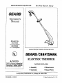
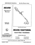
Operator's
Manual
Model No.
358.799030
(i0"
Cutting
Path)
358.799040
(13" Cutting
Path)
Always
Wear Eye Protection
8_/ /CRR
During
Operation
FTSMnNo
ELECTRIC TRIMMER
Ak WARNING:.
Read the Operator's
Manu_ and
Follow All Warnings
and Safety
Instructions.
Failure To Do So
Can Result
in Serious
I_ur_
DOUBLE
I_SULATED
• Assembly
• Maintenance
• Operation
• Repair Parts
So!d by Sears, Roebuck and C0., ,Chicag0, IU. 60684 USA
530468416-1-10/08]91
t Sears,
Roebuck
and Co. 1991
ONE
YEAR
_D
WARRANTY
ON
CRA__rSMAN
WE_DWACKER®
For.0he Year.from da.teof.pu.rchase,
when thisElectricLine Trimmer ismaintained and used according t_t_heoperatingand
mam_p.ance
_n_nmuons -,nthe operator s manual, Sears willrepairfree ofcharge any defect in materialor workmanship.
This warranty exc|udes nylon llaeor any other parts which are expendable partsand become worn during normal use.
Ifthis ElectricLine Trimmer
_ used forcommercial or rentalpurpose, thiswarrantydoes not apply,
WARRANTY SERVICE tS AVAIL&BLE BY RET_RNING
_E
UNFf TO THE NEAREST SEARS SERVI_
THE UNITED STATES
This warrantyappliesonlywhile_is productisin use intheUnited S_te_.
This
CENTER/DEPARTMENT
IN
warrantygivesyou specific
legal
rights,and you may a/sohave otherrightswhich varyfrom steretostate.
SEARS.ROEBUCKANDCO.
DEPT-D/T31CR-W
TABLE
SEAP_TOWER
CHICAGO,1L
60_,4
OF CONTENTS
WARNINGS AND SAFETY INSTRUCTIONS
...
3
KNOWYOUR
UNIT ........................
,.
5
As Introduction
..........................
5
B. Unpacldng Instructions
.................
5
C. Carton Contents .....
, .................
5
D. DoubleInsulation
Construction.......... 5
ASSEMBLY
...............................6
A. Tube Assembly ..................
_..... 6
B. AssistHandleAttachment
6
C. Pre-OperationChecks .................. 7
D. ExtensionCord Attachment ............. 7
E. OperatingPosition..................... 7
USING YOUR UNIT .........................
8
A. LineTrimmer Safety ...................8
B. OperatingInstructions
..................8
C. Trimmer LineAdvance .................8
D. CuttingMethods. ......................9
E. LineReplacement......................
10
GENERAL MAINTENANCE
.............
.o.. II
A. MaintenanceSafety. ...................
11
B. TroubleShootingChart .................11
ACCESSORIES
............................
11
PARTS AND SERVICE
..............Back Cover
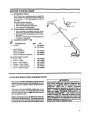
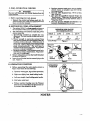
SPECIFICATIONS
Recessed
Plug
Cord
Retainer
Assist Handle
TrA'gger
Switch
MODEL:
VOLTAGE:
Motor
Housing"
AMPS:
CUTTING
PATH:
10"
AirVents
,IHi i
CUTTING
LINE:
LINE FEED:
WEIGH_.
.065"Die.lhe
I Semi-Automatic
4.0Pounds
\
MA_'n_T^OIWJRED
t_'i)ER'ONE OR MORE Or THE FOLLOWINGU_. pA_
• _
¸Line
Limiter
WARNINGS
_e
Additional
WARNING
AND
SAFETY
INSTRUCTIONS
Safety LustructiOns throughout this Manual)
- THIS POWER
UNITCANBE
DANGEROUSI
This unit canca,useserious injury or
blindness
totheoperRtorandothers.When usingan electric
trimmer,thesebasicsafetyprecautions
mast befollowed
to
reducetheriskofinjury,
fire,
and electric
shock.Fad:lureto foi_owail
instructions
canresult
inblindness
orotherserious
injury.
The operator
isresponsible
forfoUowingthewarningsand instractians
inthismanualandon theunit.
Read the
entire Operator's
Manual before assembling
and using this unit! Restrict
the use of this unit to persons
who read, understand,
and follow the warnings and instruetions
in this manual and on the unit.
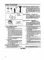
A
DANGER
@OO
NEVER
-
BLADES
WITH
THE BLADE CA1V COME OFFAND
SERIOUSLY HURT YOU AND
OTIIERS.
-
_'A
q[i
USE
THIS UNIT.
_iie_s
THIS UNITIS DESIGNED
_R
USE ONLY
FOR LINE
WARN_qG
I
B
','
TRIMMER
LINE
CAN THROW
ommcTswor rLy.
-
YOU CAN BE BLINDED
OR
Boots
_e
Protection
k
/
Foot
20 meter)
Hazard 7,one
A WARNING
HAZARD ZONE FOR THROWN
OBJECTS
- TRIMMER
LINE CAN THROW
VIOLENTLY.
-
OTHERS
CAN BE BLINDED
OBJECTS
OR
INJURED.
-
KEEP PEOPLE AND ANIMALS
(10 METERS) AWAY.
30 FEET
A WARNING
READ OPEP.ATOR'S MANUAL.
- FOLLOWALL WARNINGSAND
INSTRUCTIONS'
- FAILURE TO DO SO CAN RESULT IN
SERIOUS INJUR_
Operator's
Manual
L, ,
,,,,,
,,L
WAR ' G S AND SAFETY
A
OPERATOR
INSTRUCTIONS
SAFETY
1. DRESS PROPERLY--MwRys wea¢ eye protection.
Always wear heavy, long pants, boots, and gloves.
Wearing safety leg guards is recommended. See
"Accessories." Do not go baxefoot or wear sandals,
short pants,jewelry, loose clothing, or clothingwith
loosely hanging strops, .ties, tassels, etc.. Secure
hair so it is above shoulder length. Being fully covered will help protect you from pieces of toxic
plants such as poison ivy thrown by the .trimmer
head which could be more ofa h_azard than touching
the plant itself.
2. STAY ALEI_--Do
not o [Orate this unit when you
axe tired, ill, or under the influence of alcohol,
drugs, or medication.
3. AVOID UI_INTENTIONAL STARTING OF THE
UNIT--Avoid tmintentiona! starting of the, unit.
Be sure the trigger is in the "OFF position and
keepyour hand and fingers
away from thetrigger
whileconnecting
the unitto an extension
cordor
wfiencarryinga unitconnectedtoa power source.
4. Restrict
the use ofthisunittopersonswho read,
understand,
and followthewarningsand instructionsinthismanual and on t.he
trait.
It ELECTRICAL
SAFETY
I. Use onlya 120 A.C.voltage
supplyasshown on the
name plate ofthe unit.
2. Avoid dangerous situations. Do not use in thepresence of flammable liquids or gases to avoid creating
a fire or explosion and/or causing damage to unit.
3. WARNING--TO
REDUCE THE RISK OF ELECTRICAL SHOCK--Do not use in damp orwet 10cations or around swimming pools, hot tubs, etc. Do
.notexposetosnow,rain,orwatertoavoidthepossibility
ofelectrical
shock.
4. WARNING_Use
extension cords specifically
marked as suitable
foroutdoorappliances
having
electrical
ratingnotlessthantheratingoftheunit.
An undersizedextensioncordwillcausea drop in
Line voltage resulting in luss of power and overheating. If in doubt, use the next heavier gauge. The
smaller the gauge number, the heavier the cord.
(NOTE: Figure 4 shows the corre_ size to be used
dependingon thecordlength).
5, DO NOT ATTEMPT TO REPAIR UNIT_Inspect
theinsulation
and connectorson theunitand ex.
tensioncordbeforeeach use. Ifthereisany damage,do notuseuntildamage iSrepaired by qualified
service personnel
6. Never carry theunitby theextension
cordoryank
theextension
cord todisconnect
theunit.
7. To reducethepossibility
oftheextension
cordd!sconnecting
from theunitduringoperation,
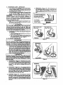
slip
the
extension
cordbehindtheTab on theCord Retaineras shown inFigure5. Plugtheextension
cord
intotherecessedplugon theImndle.Figure5.
8. Do notusethe unitifthe switchdoesnotturn_he
uniton and offproperl$Repairstotheswitchmust
be made by qu_,f_edservice
personnel
9. Keep theextehsionCordclearof operatorand obstacles
atolltimes.Do notexposecordstoheat,oil,
water,or sharp edges.
!f situations
ized Service
-4-
occur which are not eovered ln this manual,
Dealer if you need auzstance.
....
(,Continued)
10.Avoid anybodycontact
withanygroundedconductor,
sucha metalpipesorwirefences,
to avoid the
possibility
ofelectric
shock.
A UNIT SAFETY
1. Inspect entireunitbefore each we. Replace daxaaged par_. Make sure all fasteners are in place and
securely fastened,
£. Replace trimmer head parts that aze cracked,
chipped, or d_d
before using the unit.
_.
3. Use only .0_5 diameter SEARS Lazer Line _.
Never use wire, rope, string etc.
4. Use only the specified trimmer head. Make sure
the trimmer head isproperly installed and securely
fastened. Refer to _Assem@bly.
6. Use onlygenuineSEARS
accessories
as recommended forthisunit,
ii CUTTING
SAFETY
L inspect theareatobe catbeforeeachuse.Remove
objects
(rocks,
brokenglass,
nails,
wire,string,
ere.)
whichcan be thrown or become entangledinthe
trimmerhead.._lways
cuttothe.left
sideoftheunit
so thatclippings
and debriswillbe thrown away
fromyou.
2. KEEPCHILDRENAWAY--Keep
others including
children,
animals,
bystandersand helpersoutside
the60 foot(20meter)Hazard Zone.Stoplhe unit
immediately
ifyou areapproached.
3. Stop the unitand disconnectthe power source
when notin use.
4. DO NOT OVERREACH
OR STAND ON UNSTABLE SUPPOK'f--Keep firmfootingand balance.
Do notover-reach.
5. Keep thetrimmerhead below waistlevel.
6. Do notraisetheunitabove y_ourwaist.The trimmer headcancome dangerously
close
toyourbody.
7. Keep allpartsof your body away from trimmer
head when unit is running.
8. USE UNIT PROPERLY--Use
0nly forjobs expJainedinthismamml. Do notforcetheunit.This
unitisnotdesignedforedging.
A MAINTENANCE SAFETY
1. Maintain the unit according to recommended procedures. Keep the cuttingline at the proper lengu_.
2. Have all internal service performed by qualified
service
personnel
toavoidcreating
a hazardand/or
voiding your warranty.
3. DISCONNECT UNIT FROM THE POWER SUPPLYbefore perform i_.. main_n_ce.
4. Never douse or squirttheunitwith wateror any
other liqmd. Clean with a damp sponge. See
"Maintenance-- Storage,"
.
.
5. Keep theairventsdean and freeofdebristoa_id
overheating
themotor. Clean a_tercaca use._ee
"Specifications"
forlocations.
6. Use only_
genuineSEARS replacementpartsasrecommended.
A
TRANSPORTING
AND
STORAGE
1. Hand carry the unit with the motor stopped.
2. Allow the unit to cooland securethe unitbefore
storing
or transporting in a vehicle.
3. Store the unit so the Iine limiter cannot accidentally cause injury.."
4. STORE UNIT INDOORS--Store unitunplugged
ina high,dry placeout ofthereachofchildren,
use care and goodjudgmtmt.
SAVE THESE INSTRUCTIONS
•
Contact
your Author.
i
•
KNOW
m
,
,
YOUR
.i
"A.
Nil
.
,,,
I
II
I
|
,
ii
ii
i llmmI;I
I
iiii
I I •
,,i ii ii iiiiiiiii
UNIT
t,,,lll
,,ii
, H i
,.,
i
l
i
................
_i ...ii
,
i
INTRODUCTION
Your Trimmer is a versatile product developed for
small lawns and to make short work of a variety of
lawn c_re t_sks -- trimming, scalping, mowing, and
sweeping.
Special Features
Include:
• Lightweight
Construction
a Semi-Automatic
Line Advance
• Convenient
Cord Retainer
B.
UNPACKING
INSTRUCTIONS
!. After removing the contents from the carton,
check pm_ against the Carton Contents list.
2, Examine thepartsfordamage. Do notusedama ed parts.
3. _odf.y J(.ou.rSEARS dealer _ly
ifa part
is rn_s_$ng or damaged.
C.
CARTON
COr_r?NTS
!
KEY
NO.
I.
DESCRIPTION
Trimmer
2.
Assist Handle-Model 358.799080
Model 358.799040
Operator's Mant_
P/N
1
358,799030
OR 358.799040
(not shown)
Loose Parts Bag Contents:
3. Screw- Tube
4. Locknut - Tube
5, Screw- Assist Handle
6. Wing'nut - Assist Handle
7. Hex Nut - Motor Housing
8. Screw- Motor Housing
1
i
1
530-322296
530-326262
530-968416
2
2
1
1
1
1,
53O-346O34
53O-O15653
53O-34O228
530-400013
530-001543
530-348050
.........................
D. DOUBLE
INSULATION
- •
_../
..............
CONSTRUCTION
A WARNING
This unit is Double Insu]ated
to help protect
against electric shock. Doubleizsulation construction consists of two separate "layers" of electrical insulation.
Tools builtwith thisinsulation
system are not intendedtobegrounded.As a result,
theextension
cord
used with your unit can be plugged into any standard
120 volt electrical outlet
Safety precautions
must be observed
when op*
erating any electrical
tooL The double insulation
system 0nly providesadded pro.te_,
_onagainstinjury
resulting
froman interllal
electrical
insulation
failure.
All eleetrleal
repairs to this unit, including housing, switch, moto_ etc., must be diagnosed and
repaired
by qualified
service
personnel
Replacement
parts
for
a
double
insulated
appliance must be identiea]
to the parts they re.
place_ A double immlatod
appliance
is marked
with the words
"DOUBL]_
INSUI_TION"
or
"DOUBLE INSU/_TED."
The symbol (square
within a _uare)
[_ may _
be marked on the
appliance.
Failtt_e to have the unit repaired
by
Sears qualified
service
personnel
can cause the
double insul_ion
eonstmaetion
to become ineffective
and result
in seriou_
injury.
ASSEMBLY
If unit is received
assembled,
repeat
all steps
in this section
to be sui-e assembly
is correct,.
PREPARATION
This Operator's Manual is designed to help you _semble mad safely operate the unit. It is important that you read the
entiremanual to become familiar
with theunitbeforeyou beginassembly.
TOOLS NEEDED
FOR ASSEMBL_
StandardScrewdriver,
Phillips
Screwdri_,er,
Pliers.
iiiiiiiii
A.TUBE
•-
i
iiiiiii
Hll
Jill
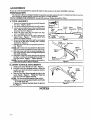
1. Remove and discard the plastic inserts (3) found in
the tubes. Figure I (inset).
2. Lay motor housing/tube assembly on a flat surface,
3. Locate the two indentations at{he end of the lower
tube,Alignthelowerindentation
withthemotor
housingas shown inFigureI,
4. Insertthe lower tube intothe upper tube (Figure t ) and align screw holes.
5. Insert the twn screws, one at a time, through the
aligned •holes. Figure I.
Thread locknut onto
screwsand tightensecurely.
6, Remove theround head,screwandhex nutlocated
at the top of the motor housingwith a Phillips
screwdriver,
Figure2.
7. S]idetheexcesswireintothetopofthemotorhvus.
ing. Figure 2.
Tl_eexcesswi_ must slide
down beyond the
areaofthemotor housingwherelowextubeenters,
8. Slidethelowertubeintothemotor housingas far
as itwill
go (about3 inches)
and alignindentations
withscrew openings.
9. Install
theround head screwand hexnutremoved
in step6. and theround head screw and hex nut
from thecarton.Figure2. Tightensecurely.
•NOTE." Be sure to install the screws in the round recesses and the nutsinthe hex recesses.
.
B.ASSIST
,,if i i
HANDLE
:_
HHHHI
I
HHI
],i
...............
.H.,
Inserts
_
Upper
fill
Lower
Screws Tube
i
i
•
........................
. ,
Lower
Motor
IndentationHousing]
Trigger" %
Handle
Locknuts
Figure 1
"-.
_
Lower
"
IndentationHex Nu{s
Motor
Figure 2
HH
INHI
I
m,,IH
HHNI
ATTACHMENT
I. Firmlypush AssistHandle onto tube,Figure3,
2. Hold theunitintheoperating
position.
Adjust,the
handle up or down thetubetoa position
com2ortablefortheuser.
3. Pass the Hex Head Screw through the hole in the
A_sistHandle, F_re 3, Thread the Wing Nut
ontothescrewand tighten
securely.
_
The recommended position is thatwhich:
1)allowsyou toholdtheassist
handlecomfortably
in the left band,and
2) places the trimmer head just dear the ground.
• See Figure 6.
,
:
,,.H
HHHUI L
,
III
I
NOTES
-6-
i
ASSEMBLY
HHI
Screw
Assist
Handle
•Wing Nut
Fibre
3
•
HI it
i _ii
i
CHECKS
2. Replace trimmer he_d parts that are cra_
• chipped, broken, or damaged in any other way before usingthetool.'
3. Use onl_ .08G"diameter line.Never usewire,
rope,string,
etc.
4. Use only the speeifiedtrimmer head. See
Specifications."
Make surethetr_m_erhead is
[Foperlyinstalled
and securely
fastened.
Referto
Using Your Unit."
5. Use only genuine SEARS accessories
or attachments recommended forthistool.
=
C. PR_E-OPERATION
,=ufRevle--I Warnings
_"
WARNING
and Safety
Instructions
in
Ithis manual
•
Before
operating
your tool, alwmys:
1. Inspect the entire tool before each use. Replace damaged parts, Make sureall
fasteners
arein
placeand securely
fastened,
ii
D.EXTENSION
1.
2.
HIll i
CORD
ii
....
i
!Hi,,ii
ii
HI
ATTACHMENT
Use only a 120 A.Co voltage supply as shown on
the nameplate of the unit to power your blower.
The extension
cord used to reach the power
source must be:
Specifically
marked
as suitable
for outdooruse.
Yhe cord mu_t be marheoLwizh the s_f-
WIRE GAUGE
RECOMlV[ENDATIONS
VOLTS
]
120
f_ 'T/A"
b. Heavy enough
to carry the current from
the power source the full length Of the extension cord to the u_Lit. Otherwise, toss of
power and overheatingcan occur_usingdamage
to the unit. Refer to Figure 4 for mi_um
wire
g_uge recommendations.
The cor_ must be
markedwith_lzeproperw_egazz_
(Appropriate
extension cords are available.}
c. In good condition.
Cord insulation must be intact with no cracks or deterioration.
Plugc0nnectors must be undamaged.
3. Secure extension
cord to the Cord Retainer
as shown in Figure 5.
4. Inser_ the cord socket into the recessed plug on the
unit. Figure 5.
•A_._=w_._
2._E
I
50_PI_
16
A.W.G.*
I8
A.W.G.=
']
100F'_
16
•A.W.G.°
Figure 4
Recessed
Socket
Cord
Figures
• J,l,
E, OPERATING
ql
iii
,,,,,,,,,,,,,,,,,,,,
i
POSITION
POSmON
Before operating
the unit, stand as shown in
• Figure 6 and check for the following:
a. Operator
,,,,,,,,,,,
on
wearing eye, leg, and foot protection.
b. Right arm slightly bent, hand holding handle.
c. Leftarm straight,
hand holdingassist
handle,
d. Unit below waistlevel
e. Without operator bending ov_ the Trimmer
Head is near and parallel to the ground and eas.
i_y contacts the material to be cut.
H_a_
6
iii
_ji
NOTES
-7-
iiiii
,LL ,
I ii ii
="l,
IIIIIIIIIi
I I
I
USING
.
ii
YOUR
I
" II/.
; 'UU,
II
111111111111111
_
11 III
IJ
iiiiiiiiiiiiiii.I I
I
iiiill]
H
UNIT
ii
ii
ii
,
_:_
**_ i ii r
i
__i
_
. ,,.Llu&£ ..................
_:
]
I llilll
iiiii
3
WARN G-THROWS OBJECTS
The rapidly moving llne causes.objects
to
be thrown vlolentI_
The shield will not
provide complete protection
to the operatot or others. The operator must wear a
safety farce shield or goggles. Always wear
heav_
!ong pan__ts and shoes or boots.
Keep others at least 30 feet (10 meters)
awa_
t
Eye
Protection
WARNING
- HAZARD ZONE
This unit will th_owobjeets
and cut. Keep
others including
children,
animals,
bystanders, and helpers at least 30 feet (10
meters) away from the operator and unit;
Stop the unit if you are approached.
WAPdNING
--
A. L_'TRIM_R"
TRIMMER
Use Only Genuine
SEARS
Reptacemen_ Parts
SAFETY
i i
B. OPERATING
,,,,,,,,
, i,,
"
.
c. Make sure the trimmer head is properly
installed
and eeeurely
fastened.
d. Use only genuine
SEARS aceessorles
or
attaehmente
as recommended.
a. Inspect the area tobeeut
before each uee.
Rem eve objects (rocks, broken glass, nails, wire,
string, etc.) which can be thrown or become entangled in the trimmer head. Always cut with
the left side of the unit so that clippings and
debris will be thrown away from you.
b. Hold the unit flrmly_
e. Keep fh-m footing
and balance.
Do not
over-reec h
d. Keep the trianmer head below waist level
e. Do not raise the unit above your waist.
The trimmer head can com e dangerously dose
to your body.
f. Keep all parts of your body away from the
trimmer Hne when the unit _s running.
g. Use only for jolm explained
in this manual,
......................
before
en-
2. Always release the Trigger switch
the unit to stop wlaen not cutting.
...................................
NOTES
--8-,
HI
H
INSTRUCTIONS
1. Allow the unit to reach full speed
tering the material
to be cut,
,.,,
HEAD
Trimmer
head oarts that are _h_;pped,
cracked, hrokemb'or damaged in any other
way can fly.apart and cause serious inju_r_
Do not use. Repl_
damagea
parts before using the ._mit.
I. OPERATOR
SAFETY
a. Always wear a face safety shield or goggles. See _Accessories/
b. Always wear heav_ long pants, shoes or
boots, and gloves. See _Accessories.* Do not
wear loose clothing,
jewel_,shortpants, sandais,or go barefoot.
Securehairso itisabove
shoulderlength.Being fullycoveredwillhelp
protect
you from piecesoftoxicplantssuchas
poisonivytlirown
by theTrimmer Heed which
couldbe more ofa hazard than touchingthe
plant i_d£
e. Do not operate this unit when you
tired, ill, or under the influence
of alcohol, drugs, or medieatioL
?
2, UNIT SAF'g'Uf '
a. Inspect
the entire unit before each use.
Replacedamaged parts. Make sureallfasteners
are in place and se_trely fastened, i
b. Use only .065" diameter
llne:"= Never use
wire, rope, string, etc.
HI
- DAMAGED
,,, ,,,,,,, i
and allow
HHI
U. _R
L/_
ADVANCE
•
You_. trimmer _ _ulp_
_th a _ml-sut_
mz_e t_er
head. Whenever thetapbutton
ispressed,
theheadautomaticzJly
advancesa pre.
determined amount of Erie.
• The line I/miter on the shield will cut the line
to the correct length.
The most effident line
len_h is maximum length allowed by line limiter.
Do not bump trimmer head on an
abrasive
surface
such as concrete,
asphalt,
or
gravel to advance
the line. Bumping the trimmer
head on an abrasive
surface can cause excessive
wear or damage the unit,
If the tine lhniter reqvJres n_ntenance or replacement,service
shouldbe performedby q_ifled_ervice
personnel
only.
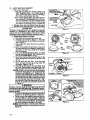
4. S.WEEPING-FIgt_e
10. Theg_ningactioaof
me rot_tin_ linecanbe usedfora quickand easy
cleanup. Keep thelineparallel
toand abovethe
surfaces
beingsweptand move t_eu_itfrom sideto
side.
To advanceline,
tapbottom
of trimmer head _ightly
on
_t_\\
_,x-x_.
"
]1 1|
the_groundwhilethe
trimmerhead isturning.
_
LineLimiter_
Cuts LineTo
ProperLength.
Line Crowded Into
Work Area
__
Does The Cutting
I Tip o_ the Line
• To Advance the Line,the trimmer head must
be turning.
I. Hold thetrimmer head parallel
to and abovea
_vassyareaofground.
2. Tap the _rimmer bead _tly
on the ground one
time. Approximately 11/2 to 3 inches of line will
be adve_d
after each tap. Figure 7.
D. CUTTING
I
_
Figure 7
.4
[Use only ,065" dlameter
iine. Other sizes ofline
I will not advance
properl_
Do not use other ma|terials
such as vnre, string, rope, eteo Wire can
|bre_
offdurmgcuttingan_dbecome
adangerous
|mlssfle
that ean cause serious i_ur_
WaONO
METHODS
•A WARNING '.............
I
RIGHT
........
Figure 8
Do not'crowd llue when cutting around _
ob-_
jecta (rocks, gravel, fence posts, ere), whie_ can ]
damage the trimmer head_ become entangled in]
the line, or be thrown emmmg a serious hazard_
•
•
The tip of the line doel the cutting.
You will
achieve the best performanoe and minimum line
wear by not crowding the line into the cutting area.
The rijght
and wrong ways areshown in _
8.
The llne will e_
remove gr_e and wee&
from around wal_, fences, trees, and flower
beds, but it a/_
_n
cut t_
tem_
ba_
of
]Alway_ wear e_Fe protection.
This unit is not de- f
'I
signed for edgmg. Never lean _over the t rmmmer]
| head. Rocks or debris ean ricochet
or be threwn |
into eyes and faee and cause blindness
or other _
/serio_ _
i
Figure 9
L TRIMIPIING- F|gm, e 9. Hold the bottom 0fthe
t_er
head about S inches above the ground and
at an angle. A.Eowonly the tip of the.l_e to make
contact. Do not force the trimmer line into the
work area.
2. SCALPING- Figure 9. The sc_)ping techaique
removes unwanted vegetation.Hold the bottom of
thetrlmmer
head about 3 inches above the gr? .und
and at an angte. Allow the tip 0f the llne to strike
_e. ground around trees, posts, monuments, etc.
3. MOWING- Figure 10. Your trimmer is ideal for
mowing in plac_ conventional law_ mowers
not reach. _ the mowingpos_tion,
keep me dne
parallel to the ground. Avoidpressingthe
head into
the ground as t_is can scalp tl_eground and damage
the unit.
,
II
Figure10
_"
E,
LENE REPLACEMENT
•
•
For proper line feed:
- Use only genuine pre_wound
spools and
.065" diameter
llde. Use of other types of
spot)Is or fines can r_sult in excessive breakage,
h_neweldiug, and improper line feed.
- Pre-wound
spools offer the most convenient method for replacing tlne as wetl as optimum performance.Be suretoalwaysreplace
thespool• thesquarecomers ofthedrivelugs
_re roundedoff,
_duced in size,
or brokenoff.
Always clean dirt and debris from the spool
and hub when performing any type .maintenance.
a W .N NS
_ro aSMOVa
Spool
To_tN_
_
TU_ LOCKsine _€_.f_f_
I
V_
I
"_
!
Figure I1
w/Line
& Stop the unit and unplug the power cord.
b. Hoidthe unit as shown in Figt_e 11. Press the
Lock Tab and turn the Lock Ring counterclockwise. Figure 11.
c. Remove theLock Ring,Tap Rutton,andSpool.
Fig,,_re!2.
d. Cleandirtand debrisfrom allparts.Inspect
all
Try_ met headpart_fordama__-.Replacedampartsor have them replacedby qualified
-serwcepersonnel.
e. Use a new SEARSprewound _ool, or rewind
the old _l
-
I_ 1 #!
Trimmer
head parts that are chipped, cracked, I
broken,
or damaged in any other way can fly[
apart and cause serious i_ur_
Do not use. Have l
damaged
parts replaced before using the unit,
1. Installing
k
with S_
Lugs
Figure 12
.o65 diameter _e.
See the _.CCESSORtES
section.
Insert 3 to 4 inches of the end ofthe line (on the
spool) through the Line Saver in the Hub. Figure 13.
g. Set the spool into the Hub. Press the spool
down; turn and lock the spool lugs under the
drive gear. Figures 12 & 13,
ho Reinstall the Tap Button and Lock Ring. Turn
the Lock Ring clockwiseand fastent_eLock
Tabs mal/fourCatcheson theHub. Figure14.
Check tobe surethelockrin_isproperly
installed
by attemptingtoturnthermgcounterclockwiseand p_
on it. Make sure the
catchesandlocktab_ppearfrom thebottom of
the head as shownin Figure 14 (insets), Be sure
the lock tab hits the edge of the cut-out when
ey_uturn the lock ring counterclockwise.
Propyreinstall if the lock ring comes off or if the
lock tab or catches do not look like those shown
in Figure 14.
£
I
•
A W,etN G
i
_AH four catches mmmt be faztened
and the lock[
| tab latched onto the lock ring. If ivmtalled meor- l
.| reetly; the Iock ringem_ fly o_aud become a dJm- ]
[gerous missile.
,,
[
i, Pult the line tochange the spool from the locked
position to the operating position. Figure 14.
j. Obtain_orrect line leng__ by pressin$,_,p button and p ,u_, g on nylon line _
If [ine extends one bicli or more ]_yond the line .limiter,
cut the line near the line liiniten Excessive line
_,n cause premiiture damage to the shield.
Approximate!y 1 1/2 to 3 inches of line cap,
be advanced each time the tap button is presseo,
Figure 14.
-_10-
• Line Saver
Figure 13
r C ES
or t.iN CAN
,
ADVANCED EACH
"_,,._ TIMETHE
TAP
_
BtHTON
IS
2;
tztst_lling
•
To replace the trimmer line on an ezistfug
spool, do the following:
a. Follow "InstatRu_ Spool w/Line," steps "a.-c., _
and remove any _me remaJni_ug
on thespool.
Do not wrap more than 40 feet of.065" di*
ameter line ontothe spool.
b. Hold spoolas shown inFigure15.
c. Insert
I116 to I/8 inchof line through theholein
theinnerrimofthespool.Figure15. Allowno
more t_m.u
i/8inchoflinetoextendbeyondthe
innerrimofthespooltoavoidinterference
with
thedrivegear.
d. Wrap line
evenlyand firmlyin thedirection
indicatedby thearrowon thespool.Figure 15.
To ensure proper line advance, avoid crossover
or crisscrossing
theline.
Line
On Spool
e. Followinstructions
in _Instailing
Spool w/
Line, _ steps "f.-j."
• If'the trimmer llne break.soft
or backs uv in
the trimmer head, followInstalling
Spoolw/
Line/steps"a.-c." Pull slackin theline until
itis
tightly wound on the spool, tea_ng 4-6 inches of
]_e extended.
-Continuewith Installing
Sp0olwi
_..
Line,"s_ps "f.-j."
Use .06s" _4_zmeter line only.
II
l
GENERAL
'
'
'
. Jml
t
' 1,,",""
i
...............
.,
i
H
HI
.
,
SHOOTING
CHART
.......CAUSE ....................
........................
REMEDY
a. Crowding trimmerlineagainst
materialbeingcut.
b. Electrical
failure.
c. None 0£ the above.
...,,
.,
a.
b,
€:
d.
Line improperly routed in head.
Line improperlywound ontospool.
Line _size incorrect.
Too little line outside he_&
on coven
e. DL_ a,_umulated
a. Line size incorrect.
spool.,
b. Incorr_
..........................
a. Back trimmer bead away fromgrassbeing
cut;allowtipof lineto.do thecutting.
b. Contactyour SEARS Service
Center/Depc.
_.€" Contact _our S_RS
Service
Center/Dept.
8- Remove cove_ Check linerouting.
eve.ly.
b.r
md
c. Use only.06_
dlameterllne,
& Remove cover. Pu]t4" of line to outside.
e. CI_ coyer.
a. Use only .065" diameter llne.
b. Use proper spool.
e. Crowdi_ line ags_st material being cuL
e. Cut with tip of line.
d. Cuttinf at higherspeed _,,necessmT.
d. Reducecuttingspeed.
a. Line improperly routed in hea_
a. Remove cover.Check linerouting.
b. Line size incorrect.
b. Use only ,,06_" _eter
line.
......
,JLHm,,,,
,
,,,,,,,
a. [£u improperly muted in head.
a. Remove cover. Check [ine routing.
b. Line size inco_
b. Use only.06_" diameter line.
c. Reducespeed around hard objects.
c. Cuttinff at high speed around hard objects.
d. ,,Crowding RUe S_ainst material bein_._t.
....
d: cut
o,, tine.
a. Remove cover.Pull4" oflinetooutside.
a, Too little Rue outside of head.
b. Linesize incorro_
b. Use only .065"diameterline.
M
Line pullsback
into head.
i
T
Line releases
continu0tLsly.
Line usage is
excessive.
,
5. ReFlace L_mmer
head parts that are cracked,
chipped, broken, or damaged in any other way beford using the tool.
6. Use only .065"diameter llne.Neverusewire,
rope,string,
,etc.
7. Use only genuine SEARS replacement
parts
ai recommended.
8. Ixmpect the entire tool Replace damaged psxts.
Check forfuelleaksand make sureall fasteners
are
inplaceand securely
fastened.
•
Trimmer Head stops
under a loador does
not turnwhen
switch is pressed.
Line does not advance or breaks
while cutting.
Line welds
ontospool,
r
.........
1. Mam la m the tool according
to reeommen_dp_'_ed_es.
K£-epthe cut_Angiineat the
_ropertength.
2. Disconnect
power source before performang
m_Lintenanee.
3. K_ep the unit clean.
Use a spongedampened
with a sOlUtion
ofmildsoapand water.Do notuse
s_qlvents or petroleum bassi cleaner of may kind.
4. Keep air vente free ot debris at all times.
SYMPTOM
of Line
Figure 15
II
SAFETY
*
B. TROUBLE
,
MAENTENANCE
A. MAINTENANCE
*
IIIIIIII
xrow ,,,,
""I'H{H
IIIHHHHHHH
H
I
IIIHH
III
Hill
IIII
{ HI
I
l, lii
..............
ACCESSORIES
....................... STOC NO. .......
SAFETY GOGGLES
.................
.............................................
71-85707
SPOOL W/LINE
06_" DIA.
..............................................
71-85830
.............................................
71-;57020
EXTENSION CORD (100 R.) ..........
,,,_.........................................
71-85772
BULK LINE
--_t00 F_ .............
--200 FT..............
........
, ....................................
7Z-85607
. ..............
: .......................
. .....
71_769
•
--400 F_...
• ........
_ ............................
_30-068416
'0P RATOR'S
MANUAL ..........
,..................
"
,
• .
The Model Narnber wit! be found below the top handle with the Seriat
Number. Always mention the Model Number when requesting service or
repair parts for your unit.
Atlparts listed herein may be ordered from any Sears Service Center and
most Sears S_res.
Operator's
Manual
WHEN ORDERING REPAIR PARTS ALWAYS GIVE THE FOLLOWING
INFORMATION AS SHOWN IN THIS LIST:.
1.
The pAI_ NUMBER
3.
The PART DESCRIPTION
2.
The MODEL NUMBER
4.
The NAME OF ITEM --
358.799030
358.799040
Electric
Trimmer
the pa_.s you neeaare not s_ockea _oca_y, you.- order wilt be transmitted
to a Sears Repair Parts Distribution Center for handling.
Model No.
When you buy merchandise from
Sears you get an extra val_e that
nobody else can offer-- Sears
Service.
358.799030
(10" Cutting
Path)
358.799040
(13" Cutting
Acrosstown oracrossthecountry,
SearsServiceisalwaysnea_,pro.
riding trustworth
Z competent
servicetechnicians
using only
Searsspecified factory
parts.
Path)
How to Order
Repair
Parts
SEARS
SERVICE
IS AT YOUR
Your SearsMerchandisetakeson added valuewhen you discover
that Searshas ServiceUnits throughoutthe country.Each is
staffed
by Sears-Trained, professional
technicians
usingSears approvedmethods•
SERVICE
Soldby Sears,Roebuck and Co.,Chicago,IlL60684 USA
.,
530-068416-I-I0108/91
L


![User's Manual AH-480 Series [Machine / Software]](http://vs1.manualzilla.com/store/data/006867875_1-b2cd01726e15f409a063f19433f9385d-150x150.png)