1
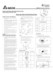
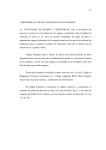
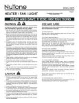
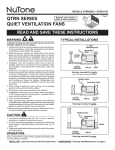
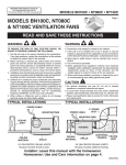
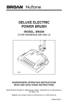
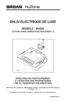
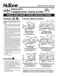
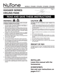
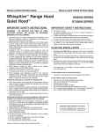
MODEL 788CHNTC
Page 1
DECORATIVE VENTILATION
FAN WITH LIGHT
Register your product
online at www.nutone.ca
READ AND SAVE THESE INSTRUCTIONS
TYPICAL INSTALLATIONS
WARNING
TO REDUCE THE RISK OF FIRE, ELECTRIC SHOCK, OR
INJURY TO PERSONS, OBSERVE THE FOLLOWING:
1. Use this unit only in the manner intended by the manufacturer.
If you have questions, contact the manufacturer at the
address or telephone number listed in the warranty.
2. Before servicing or cleaning unit, switch power off at service
panel and lock the service disconnecting means to prevent
power from being switched on accidentally. When the service
disconnecting means cannot be locked, securely fasten a
prominent warning device, such as a tag, to the service panel.
3. Installation work and electrical wiring must be done by a qualified
person(s) in accordance with all applicable codes and standards,
including fire-rated construction codes and standards.
4. Sufficient air is needed for proper combustion and exhausting of gases through the flue (chimney) of fuel burning
equipment to prevent backdrafting. Follow the heating
equipment manufacturer’s guideline and safety standards
such as those published by the National Fire Protection
Association (NFPA), and the American Society for Heating,
Refrigeration and Air Conditioning Engineers (ASHRAE),
and the local code authorities.
5. When cutting or drilling into wall or ceiling, do not damage
electrical wiring and other hidden utilities.
6. Ducted fans must always be vented to the outdoors.
7. Do not install in a tub or shower enclosure.
8. Not for use in kitchens.
9. This unit must be grounded.
10. This unit is U.L. listed. Type I.C. inherently protected.
11. When applicable local regulations comprise more
restrictive installation and/or certification requirements,
the aforementioned requirements prevail on those of this
document and the installer agrees to conform to these at
his own expenses.
12. When performing installation, servicing or cleaning this unit,
it is recommended to wear safety glasses and gloves.
CAUTION
!
1. For general ventilating use only. Do not use to exhaust
hazardous or explosive materials and vapors.
2. This product is designed for installation in FLAT CEILINGS
ONLY. Do not mount this product in a wall.
3. The light fixture assembly must be mounted to the fan
housing assembly included with this product. Do not mount
the light fixture assembly to a wiring outlet box.
4. To avoid motor bearing damage and noisy and/or
unbalanced impellers, keep drywall spray, construction
dust, etc. off power unit.
5. Please read specification label on product for further
information and requirements.
Installer: Leave this manual with the
homeowner.
Homeowner: Use and Care
information on page 4.
2” x 4”
CEILING
JOIST or
TRUSS
CEILING
JOIST
2” x 4”
CEILING
JOIST or
TRUSS
HOUSING
HOUSING
HOUSING
HOUSING
GRILLE
PAN
CEILING
MATERIAL
GRILLE
PAN
GLASS
LIGHT SHADE
CEILING
MATERIAL
GLASS
LIGHT SHADE
HOUSING MOUNTED
DIRECTLY TO JOIST
2” x 6” (or larger)
Discharge parallel to joists.
HOUSING MOUNTED
TO 2” x 4” TRUSS
Discharge parallel to joists.
ADDITIONAL
FRAMING*
HOUSING
HOUSING
"I"
JOIST CEILING
MATERIAL
"I "
JOIST
GLASS LIGHT SHADE
GRILLE
PAN
HOUSING MOUNTED TO “I” JOIST
Requires additional framing
for mounting.
Discharge parallel to joists.
* Additional framing must be a 2” x 6” (minimum height), at least 9 inches long.
PLAN THE INSTALLATION
INSULATION
(Place around and
over fan housing.)
ROOF CAP*
(with built-in
damper)
FAN
HOUSING
POWER
CABLE*
Seal gaps
around
housing.
Keep duct
runs short
OR
4-IN. ROUND
DUCT* Seal duct
*Purchase
joints with 4-IN. ROUND
separately.
tape.
ELBOWS*
WALL CAP*
(with built-in
damper)
MODEL 788CHNTC
Page 2
INSTALL THE HOUSING
PREPARE THE HOUSING
New Construction
1. Choose the location for your fan/light in the ceiling. For
best possible performance, use the shortest possible duct
run and a minimum number of elbows.
TAB
1. Unplug blower and remove (3) screws securing blower
assembly to housing.
TAB
BOTTOM EDGE OF JOIST
MOUNTING SCREWS
2. Position fan housing against joist so that bottom
edge of housing will be flush with finished ceiling.
Additional positioning feature for 1/2” thick
ceiling material:
Bend two tabs, on side of housing, 900 outward. Lift
housing until tabs contact bottom edge of joist.
3. Use (4) mounting screws (included) to attach housing
to joist.
Existing Construction
1. Choose the location for your fan/light in the ceiling. For
best possible performance, use the shortest possible duct
run and a minimum number of elbows.
2. Remove blower assembly from housing and set blower
assembly aside.
2. In attic,
position fan
housing
against joist.
Trace outline
of housing
on ceiling
material.
3. Set housing aside
and cut ceiling
opening slightly
larger than marked.
3. Remove wiring plate from housing and set plate aside.
MODEL 788CHNTC
Page 3
SEAL BETWEEN CEILING
MATERIAL & HOUSING
4. Place housing in
opening so that
its bottom edge is
flush with finished
ceiling. Screw
housing to joist
through holes in
housing as shown.
5. Seal between
ceiling material and
housing to prevent
air leakage.
FINISH THE INSTALLATION
MOUNTING SCREWS
INSTALL THE DUCTWORK
NOTE: The duct connector has a counter-balanced damper
flap. The flap will be “open” approx. 1” when duct connector
is attached to housing. This design permits insulation to be
in direct contact with fan/light housing per UL (Underwriters
Laboratories) standards. The slightest backdraft, however,
will close the damper flap, preventing air from entering unit
or finished space.
1. Connect 4” round
duct to damper/
duct connector
and extend duct
to outside through
a roof or wall cap.
Check damper to
make sure that it
opens freely. Tape
all duct connections to make them secure and air tight.
1. Re-install blower
assembly removed
in Step 1 under
“PREPARE THE
HOUSING”. Plug blower
into BLACK receptacle.
CONNECT THE WIRING
METAL
WASHER
SCHEMATIC WIRING DIAGRAM
LIGHT
SWITCH
RED
BLU
LIGHT
(WHITE)
WH T
VENT
SWITCH
BLK
BLK
VENT
(BLACK)
WH T
2. Attach grille pan
mounting brackets to
housing with screws
(included). Make sure
brackets face inward.
FELT
WASHERS
BLK
WHT
LINE WH T
IN
GRD
BE0004A
GRD
UNIT
SWITCH BOX
BLACK
RED
WHITE
GROUND
(bare)
BLUE
BLACK
RECEPTACLE
(FAN)
SWITCH BOX
LIGHT
FAN
WHITE
RECEPTACLE
(LIGHT)
DUAL CONTROL
(purchase separately)
120 VAC LINE IN
1. Wire unit as shown. Re-install wiring plate removed in
Step 2 under “PREPARE THE HOUSING”.
2. Run electrical cable as direct as possible to unit. Do not allow
cable to touch sides or top of unit after installation is complete.
BD0030
3. Locate grille pan
over fan housing and
connect light plug into
WHITE receptacle in fan
housing.
4. Attach grille pan to
mounting brackets with
(2) screws (included).
5. Thread rod onto
threaded stud in center
of grille pan. Tighten rod
securely.
FELT
WASHER
FINIAL
NUT
BD0031
6. Install bulbs. Use 13-watt
(maximum), GU24 type,
fluorescent bulbs.
7. Place washers and glass
shade over mounting
rod and align shade over
grille pan. Secure shade
to grille pan with washer
and finial nut as shown.
8. Restore electrical power
and check operation of
the unit.
MODEL 788CHNTC
Page 4
USE AND CARE
USE AND CARE
WARNING: DISCONNECT ELECTRICAL POWER SUPPLY AND
LOCK OUT SERVICE PANEL BEFORE CLEANING OR SERVICING
THIS UNIT.
CLEANING
BULB REPLACEMENT
Remove glass shade. Replace bulbs as required. Reinstall glass
shade.
Use 13-watt (maximum), GU24 type, fluorescent bulbs with a M.O.L.
(Maximum Overall Length) of 4.8 inches or less.
MOTOR LUBRICATION
The motor is permanently lubricated. Do not oil or disassemble motor.
KEY NO.
1
2
3
4
5
6
7
8
9
A
PART NO.
99526716
97018649
99271452
97018749
99160441
97018781
97018750
97018804
97018729
97018717
B
97018748
WARRANTY
DESCRIPTION
Glass Shade
Shade Mounting Hardware
Lamp, 13 W GU24 Type Fluorescent (2 req.)
Blower Assembly (includes key no. 5 - 3 req.)
Screw, Motor no. 8-32 x .275” (3 req.)
Grille Bracket Assembly
Wire Panel Assembly
Damper / Duct Connector
Housing Assembly
Light Fixture Assembly
(includes key nos. 1, 2 & B)
Grille Pan Assembly
(Does not include key no. 3)
Order replacement parts by “PART NO.” - not by “KEY NO.”
8
9
B
6
3
2
4
5
1
2
BROAN-NUTONE CANADA INC.
ONE-YEAR LIMITED WARRANTY
Broan-NuTone Canada warrants to the original consumer purchaser of its products that such
products will be free from defects in materials or workmanship for a period of one (1) year from
the date of original purchase. THERE ARE NO OTHER WARRANTIES, EXPRESS OR IMPLIED,
INCLUDING, BUT NOT LIMITED TO, IMPLIED WARRANTIES OF MERCHANTABILITY OR FITNESS
FOR A PARTICULAR PURPOSE.
During this one-year period, Broan-NuTone Canada will, at its option, repair or replace,
without charge, any product or part which is found to be defective under normal use and service.
THIS WARRANTY DOES NOT EXTEND TO FLUORESCENT LAMP STARTERS OR TUBES, BULBS
OR BATTERIES, FILTERS, DUST, ROOF CAPS, WALL CAPS AND OTHER ACCESSORIES FOR
DUCTING. This warranty does not cover (a) normal maintenance and service or (b) any products
or parts which have been subject to misuse, negligence, accident, improper maintenance or
repair (other than by Broan-NuTone Canada or an authorized representative), faulty installation
or installation contrary to recommended installation instructions.
The duration of an implied warranty is limited to the one-year period as specified for the express
warranty.
BROAN-NUTONE CANADA’S OBLIGATION TO REPAIR OR REPLACE, AT BROAN-NUTONE
CANADA’S OPTION, SHALL BE THE PURCHASER’S SOLE AND EXCLUSIVE REMEDY UNDER
THIS WARRANTY. BROAN-NUTONE CANADA SHALL NOT BE LIABLE FOR INCIDENTAL,
CONSEQUENTIAL OR SPECIAL DAMAGES ARISING OUT OF OR IN CONNECTION WITH PRODUCT
USE OR PERFORMANCE. This warranty supersedes all prior warranties.
To qualify for warranty service, you must (a) notify Broan-NuTone Canada at the address or
telephone number stated below, (b) give the model number and part identification and (c) describe
the nature of any defect in the product or part. At the time of requesting warranty service, you
must present evidence of the original purchase date.
IF YOU NEED ASSISTANCE OR SERVICE:
For the location of your nearest Broan-NuTone Canada Inc. dealer:
Dial Toll Free: 1-888-882-7626
Please be prepared to provide:
• Product model number • Date and proof of purchase
• The nature of the difficulty
Broan-NuTone Canada Inc. 1140 Tristar Drive, Mississauga, Ontario L5T 1H9
7
A
TO CLEAN FAN ASSEMBLY:
Remove grille pan and unplug fan assembly (BLACK receptacle).
Gently vacuum fan, motor and interior of housing. METAL AND
ELECTRICAL PARTS SHOULD NEVER BE IMMERSED IN WATER.
Released February 2013
SERVICE PARTS
TO CLEAN GLASS SHADE AND GRILLE PAN:
Remove glass shade. Shade can be wiped clean with a mild detergent
solution or glass cleaner and dried with a soft cloth. Remove
2 bulbs. Grille pan may be gently vacuumed and wiped clean with
a soft cloth. Never use abrasive cloth, steel wool pads or scouring
powders on glass shade or grille pan. METAL AND ELECTRICAL
PARTS SHOULD NEVER BE IMMERSED IN WATER.
REPLACEMENT PARTS AND REPAIRS:
In order to ensure your unit remains in good working condition, you must use Broan-NuTone
genuine replacement parts only. Broan-NuTone genuine replacement parts are specially
designed for each unit and are manufactured to comply with all the applicable certification
standards and maintain a high standard of safety. Any third party replacement part used may
cause serious damage and drastically reduce the performance level of your unit, which will
result in premature failing. Broan-NuTone also recommends to contact a Broan-NuTone
certified service depot for all replacement parts and repairs.
79040194A