1
CEILING VENTILATORS/VENTILATEURS DE PLAFOND
MODELS/MODÈLES HD50C • HD80C
READ AND SAVE
THESE INSTRUCTIONS
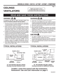
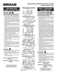
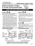
TYPICAL INSTALLATIONS
POWER CABLE
MOUNTING TABS
CEILING
JOIST
WARNING
TO REDUCE THE RISK OF FIRE, ELECTRIC SHOCK, OR
INJURY TO PERSONS, OBSERVE THE FOLLOWING:
1. Use this unit only in the manner intended by the manufacturer.
If you have questions, contact the manufacturer at the
address or telephone number listed in the warranty.
2. Before servicing or cleaning unit, switch power off at
service panel and lock the service disconnecting means
to prevent power from being switched on accidentally.
When the service disconnecting means cannot be locked,
securely fasten a prominent warning device, such as a tag,
to the service panel.
3. Installation work and electrical wiring must be done by
qualified personnel in accordance with all applicable codes
and standards, including fire-rated construction codes and
standards.
4. Sufficient air is needed for proper combustion and
exhausting of gases through the flue (chimney) of fuel
burning equipment to prevent backdrafting. Follow the
heating equipment manufacturer’s guideline and safety
standards such as those published by the National Fire
Protection Association (NFPA), and the American Society
for Heating, Refrigeration and Air Conditioning Engineers
(ASHRAE), and the local code authorities.
5. When cutting or drilling into wall or ceiling, do not damage
electrical wiring and other hidden utilities.
6. Ducted fans must always be vented to the outdoors.
7. If this unit is to be installed over a tub or shower, it must
be marked as appropriate for the application and be
connected to a GFCI (Ground Fault Circuit Interrupter) protected branch circuit.
8. Never place a switch where it can be reached from a tub
or shower.
9. This unit must be grounded.
10. When applicable local regulations comprise more
restrictive installation and/or certification requirements,
the aforementioned requirements prevail on those of this
document and the installer agrees to conform to these at
his own expenses.
11. When performing installation, servicing or cleaning this
unit, it is recommended to wear safety glasses and
gloves.
CEILING
MATERIAL
GRILLE
HOUSING MOUNTED DIRECTLY TO JOIST
2” x 6” (or larger) Discharge parallel to joists.
POWER CABLE
MOUNTING
TABS
2” x 4”
CEILING
JOIST or
TRUSS
HOUSING
CEILING
MATERIAL
BH0027A
GRILLE
HOUSING MOUNTED TO 2” x 4” TRUSS
Requires additional framing for mounting tabs.
Discharge parallel to joists.
ADDITIONAL
FRAMING*
POWER CABLE
MOUNTING
TABS
HOUSING
“I”
JOIST
CEILING
MATERIAL
BH0028A
GRILLE
“I ”
JOIST
HOUSING MOUNTED TO “I” JOIST
Requires additional framing for mounting tabs.
Discharge parallel to joists.
4” ROUND
DUCT
POWER CABLE
MOUNTING TABS
HOUSING
CEILING
MATERIAL
ADDITIONAL
CEILING
FRAMING*
JOIST
GRILLE
BH0029A
HOUSING MOUNTED TO ADDITIONAL FRAMING
Discharge 90° to joists.
CAUTION !
Installer: Leave this manual with the
homeowner.
Homeowner: Use and Care information
on page 4.
ADDITIONAL
FRAMING*
2” x 4”
CEILING
JOIST or
TRUSS
4” ROUND
DUCT
POWER CABLE
1. For general ventilating use only. Do not use to exhaust
hazardous or explosive materials and vapors.
2. To avoid motor bearing damage and noisy and/or
unbalanced impellers, keep drywall spray, construction
dust, etc. off power unit.
3. Please read specification label on product for further
information and requirements.
AVERTISSEMENT
HOUSING
BH0026A
MOUNTING TABS
HOUSING
2” x 4”
CEILING
JOIST or
TRUSS
CEILING
MATERIAL
GRILLE
ADDITIONAL
FRAMING*
2” x 4”
CEILING
JOIST or
TRUSS
HOUSING MOUNTED TO 2” x 4” TRUSS
Requires additional framing for mounting tabs.
Discharge 90° to joists.
POWER CABLE
4” ROUND
DUCT
MOUNTING TABS
HOUSING
“I”
JOIST
BH0031A
Register your product
online at www.broan.ca
CEILING GRILLE
MATERIAL
LIRE ET CONSERVER
CES DIRECTIVES
ADDITIONAL
FRAMING*
“I”
JOIST
HOUSING MOUNTED TO “I” JOIST
Requires additional framing for mounting tabs.
Discharge 90° to joists.
*Additional framing must be a 2” x 6” (minimum height), at
least 9-inch long.
AFIN DE RÉDUIRE LES RISQUES D’INCENDIE,
D’ÉLECTROCUTION OU DE BLESSURES CORPORELLES,
OBSERVEZ LES DIRECTIVES SUIVANTES :
1. N’utilisez cet appareil que de la façon prévue par le
manufacturier. Si vous avez des questions, contactez le
manufacturier à l’adresse ou au numéro de téléphone
indiqué dans la garantie.
2. Avant de nettoyer ou de réparer l’appareil, coupez le
courant au panneau d’alimentation et verrouillez-en
l’accès afin d’éviter sa remise en marche accidentelle. Si
le panneau d’alimentation ne peut être verrouillé, apposez
un avertissement bien en évidence, par exemple une
étiquette de couleur vive.
3. Les travaux d’installation et de raccordement électrique
doivent être effectués par du personnel qualifié en respectant
les normes et règlements en vigueur, y compris les normes
et codes du bâtiment en matière de prévention d’incendie.
4. Une circulation d’air efficace est requise afin d’assurer
la combustion et l’évacuation complète des gaz par la
cheminée des appareils à combustion pour prévenir les
retours de cheminée. Conformez-vous aux instructions et
aux standards de sécurité des manufacturiers d’appareils
de chauffage, tels qu’ils sont publiés par la National Fire
Protection Association (NFPA) et l’American Society for
Heating Refrigeration and Air Conditioning (ASHRAE)
ainsi que les responsables des codes locaux.
5. Lorsque vous coupez ou perforez un mur ou un plafond,
prenez garde de ne pas endommager les fils électriques
ou autre installation qui pourraient y être dissimulés.
6. Les ventilateurs avec conduits doivent toujours évacuer
l’air à l’extérieur.
7. Si cet appareil doit être installé au-dessus d’une douche
ou d’une baignoire, il doit être conçu pour cette application
et être raccordé à un circuit protégé par un disjoncteur de
fuite à la terre (DDFT).
8. Ne jamais placer un interrupteur à un endroit pouvant être
accessible depuis une baignoire ou une douche.
9. Cet appareil doit être mis à la terre.
10. Lorsqu’une réglementation est en vigueur localement et
qu’elle comporte des exigences d’installation et/ou de
certification plus restrictives, lesdites exigences prévalent
sur celles de ce document et l’installateur entend s’y
conformer à ses frais.
11. Il est recommandé de porter des lunettes et des gants
de sécurité lors de l’installation, de l’entretien ou de la
réparation de cet appareil.
ATTENTION !
1. Pour utilisation de ventilation générale seulement. Ne
l’utilisez pas pour évacuer des vapeurs ou des matières
dangeureuses ou explosives.
2. Afin d’éviter tout dommage au roulement du moteur et
de débalancer ou de rendre bruyante la roue du moteur,
gardez votre appareil à l’abri des poussières de gypse et
de construction/rénovation, etc.
3. Nous vous recommandons de lire l’étiquette indiquant les
caractéristiques de votre ventilateur pour de plus amples
renseignements et exigences.
Installateur : laissez ce manuel
au propriétaire.
Propriétaire : voir l’information sur
l’utilisation et l’entretien à
la page 4.
Enregistrez votre produit
en ligne à www.broan.ca
INSTALLATIONS TYPES
TYPICAL INSTALLATIONS
INSTALLATIONS TYPES
CÂBLE D’ALIMENTATION
BRIDES
DE MONTAGE
4” ROUND
DUCT
SOLIVE
DE PLAFOND
BOÎTIER
MATÉRIAU
DU PLAFOND
HOUSING
CÂBLE D’ALIMENTATION
STRUCTURE
ADDITIONNELLE*
BRIDES
DE MONTAGE
MATÉRIAU
DE PLAFOND
BOÎTIER
SOLIVE DE
PLAFOND DE
2 po x 4 po
ou FERME
DE TOIT
GRILLE
BH0027F
BOÎTIER MONTÉ SUR UNE FERME DE TOIT DE 2 po x 4 po
Requiert une structure additionnelle pour les brides de
montage. Évacuation parallèle aux solives.
CÂBLE D’ALIMENTATION
STRUCTURE
ADDITIONNELLE*
BRIDES
DE MONTAGE
BOÎTIER
SOLIVE
EN « I »
MATÉRIAU
DE PLAFOND
GRILLE
SOLIVE
EN « I »
BOÎTIER MONTÉ SUR UNE SOLIVE EN « I »
Requiert une structure additionnelle pour les brides de
montage. Évacuation parallèle aux solives.
CONDUIT ROND
CÂBLE D’ALIMENTATION DE 4 po
BRIDES DE MONTAGE
BOÎTIER
MATÉRIAU
DE PLAFOND
GRILLE
MOUNTING
TAB
CONDUIT ROND
DE 4 po
CÂBLE
D’ALIMENTATION
BOÎTIER
BRIDE
DE MONTAGE
GRILLE
BOÎTIER MONTÉ DIRECTEMENT SUR UNE SOLIVE
2 po x 6 po (ou plus grand). Évacuation parallèle aux solives.
SOLIVE DE
PLAFOND DE
2 po x 4 po
ou FERME
DE TOIT
POWER
CABLE
STRUCTURE
ADDITIONNELLE* SOLIVE
DE PLAFOND
BOÎTIER MONTÉ SUR UNE STRUCTURE ADDITIONNELLE
Évacuation à 90°des solives.
CONDUIT ROND
CÂBLE D’ALIMENTATION DE 4 po
BRIDES DE MONTAGE
BOÎTIER
SOLIVE DE
GRILLE STRUCTURE SOLIVE DE
PLAFOND DE
PLAFOND DE
MATÉRIAU ADDITIONNELLE* 2 po x 4 po
2 po x 4 po
DE PLAFOND
ou FERME
ou FERME
DE TOIT
DE TOIT
BOÎTIER MONTÉ SUR UNE FERME DE TOIT DE 2 po x 4 po
Requiert une structure additionnelle pour les brides de
montage. Évacuation à 90°des solives.
BH0032A
SUSPENDED
CEILING MATERIAL
MATÉRIAU DE
PLAFOND SUSPENDU
GRILLE
SUSPENDED CEILINGS
Housing hung with wires - 3-point mount.
GRILLE
PLAFONDS SUSPENDUS
Boîtier suspendu par des fils. Montage en 3 points.
INSTALL THE HOUSING
INSTALLATION DU BOÎTIER
- PLEASE NOTE THE FOLLOWING INSTALLATION ILLUSTRATIONS SHOW
2 X 6 JOISTS. IF YOU HAVE A TRUSS OR “I”-JOIST
INSTALLATION, MOUNT THE VENTILATOR TO THE
ADDITIONAL FRAMING IN THE SAME MANNER.
(Additional framing must be a 2” x 6” (minimum height),
at least 9-inches long).
- VEUILLEZ PRENDRE NOTE LES ILLUSTRATIONS D’INSTALLATION SUIVANTES
MONTRENT DES SOLIVES DE 2 po x 6 po. SI VOUS AVEZ
UNE FERME DE TOIT OU UNE SOLIVE EN « I », FIXER
LE VENTILATEUR À LA STRUCTURE ADDITIONNELLE
DE LA MÊME MANIÈRE. (La structure additionnelle doit
être de 2 po x 6 po (hauteur minimale), et d’au moins
9 po de long).
New Construction
Construction neuve
1. Choose the location for your fan in the ceiling. For 1. Déterminer l’emplacement du ventilteur au plafond.
Pour un fonctionnement optimal, utiliser les conduits
best possible performance, use the shortest possible
les plus courts et le moins de coudes possible.
duct run and a minimum number of elbows.
2. Positionner les brides de
2. Position mounting brackets
montage contre la solive afin
against joist so that bottom
HOLES
que le bord inférieur du boîtier
edge of housing will be flush
TROUS
soit au ras du plafond fini.
with finished ceiling.
TAB
Caractéristique de
Additional positioning PATTE
positionnement additionnelle
feature for 5/8”, 1”, & 1-1/4”
1-1/4
pour les matériaux de
thick ceiling material:
1
5/8
plafond de 5/8 po, de 1 po
Holes in corners of housing
et de 1¼ po d’épaisseur :
are labeled with various
BOTTOM EDGE OF JOIST
ceiling material thicknesses.
BORD INFÉRIEUR DE LA SOLIVE
Des trous situés dans les
Position housing so bottom
coins du boîtier comportent l’indication de différentes
edge of joist is visible through a matched set of
épaisseurs de matériau de plafond. Positionner le
holes. The housing is now in the proper position
boîtier afin que le bord inférieur de la solive soit
for that ceiling material thickness.
visible à travers le jeu de trous correspondant
à l’épaisseur désirée. Le boîtier est maintenant
Additional positioning feature for 1/2” thick
correctement en place pour cette épaisseur
ceiling material:
de plafond.
Bend two tabs, on side of housing, 90° outward. Lift
housing until tabs contact underside of joist.
Aide supplémentaire au positionnement pour
le matériau de plafond de 1/2 po d’épaisseur :
Mark the keyhole slot on both mounting brackets.
Plier les deux pattes de chaque côté du boîtier à 90°
vers l’extérieur. Soulever le boîtier jusqu’à ce que les
pattes entrent en contact avec la face intérieure de
la solive.
Marquer l’emplacement du trou en forme de serrure
sur les deux brides de montage.
3. Set housing aside and drive
nails partially into joist at the
top of both keyhole marks.
CONDUIT ROND
CÂBLE D’ALIMENTATION DE 4 po
3. Mettre le boîtier de côté et clouer
partiellement des clous dans la
solive au sommet des deux
marques des trous en forme
de serrure.
BR0004
BRIDES DE MONTAGE
BOÎTIER
SOLIVE
SOLIVE MATÉRIAU GRILLE STRUCTURE
EN « I »
ADDITIONNELLE*
EN « I » DE PLAFOND
BOÎTIER MONTÉ SUR UNE SOLIVE EN « I »
Requiert une structure additionnelle pour les brides de
montage. Évacuation à 90°des solives.
*La structure additionnelle doit être de 2 po x 6 po (hauteur
minimale) et au moins de 9 po de longueur.
4. Hang housing from nails
and pound nails tight. To
ensure a noise-free mount,
pound another nail through
the top hole of each
mounting tab.
2
4. Suspendre le boîtier à l’aide
des clous et les enfoncer
complètement. Pour assurer
un fonctionnement silencieux,
enfoncer un autre clou dans le
trou supérieur de chaque bride
de montage.
INSTALLLATION DU BOÎTIER (suite)
INSTALL THE HOUSING (continued)
Existing Construction
Construction existante
1. Choose the location for your fan in the ceiling. For best
possible performance, use the shortest possible duct run and
a minimum number of elbows.
2. In attic, position mounting brackets against joist. Trace outline
of housing on ceiling material.
3. Set housing aside and cut ceiling opening slightly larger than
marked.
4. Place housing in opening so that its bottom edge is flush with
finished ceiling. Nail to joist through keyhole on both sides.
To ensure a noise-free installation, drive another nail through
the top hole of each mounting bracket.
5. Additional mounting holes are provided for installations where
access from above is inconvenient or not possible. Nail or
screw housing directly to joists or framing.
1. Choisir l’emplacement du ventilateur dans le plafond. Pour
obtenir la meilleure performance possible, utiliser un nombre
restreint de coudes et un conduit le plus court possible.
2. Depuis le grenier, positionner les brides de montage contre la
solive. Tracer le contour du boîtier sur le matériau du plafond.
3. Mettre le boîtier de côté et découper une ouverture dans le
plafond légèrement plus grande que la marque.
4. Placer le boîtier dans l’ouverture afin que son bord inférieur
soit au ras du plafond fini. Clouer le boîtier sur la solive à
travers les trous en forme de serrure des deux côtés. Pour
assurer un fonctionnement silencieux, enfoncer un clou dans
le trou supérieur de chaque bride de montage.
5. Des trous de montage supplémentaires sont prévus pour les
installations où l’accès par le dessus n’est pas pratique ou
impossible. Clouer ou visser le boîtier directement aux solives
ou à la structure.
INSTALLATION DU CONDUIT
INSTALL THE DUCTWORK
1. Snap the damper/duct connector onto housing. Make sure
that tabs on the connector lock into slots in housing. Top of
damper/duct connector should be flush with top of housing.
2. Connect 4” round duct to damper/duct connector and extend
duct to outside through a roof or wall cap. Check damper to
make sure that it opens freely. Tape all duct connections to
make them secure and air tight.
1. Enclencher le raccord de conduit sur le boîtier. S’assurer que
les pattes du raccord de conduit soient bien insérées dans
les fentes du boîtier. Le dessus du raccord de conduit doit
être au même niveau que le dessus du boîtier.
2. Relier un conduit rond de 4 po au raccord de conduit et
acheminer le conduit vers l’extérieur jusqu’au capuchon
de mur ou de toit. Vérifier que le clapet s’ouvre librement.
ADDITIONAL MOUNTING HOLES
Sceller hermétiquement tous les joints avec du ruban adhésif
TROUS DE MONTAGE ADDITIONNELS
en toile.
BR0007
BD0003
CONNECT THE WIRING
BRANCHEMENT ÉLECTRIQUE
1. Wire unit following diagram. Run electrical cable as direct as
possible to unit. Do not allow cable to touch sides or top of
unit after installation is complete.
1. Brancher l’appareil selon le schéma. Acheminer le câble
électrique le plus directement vers l’appareil. Une fois
l’installation complétée, ne pas laisser le fil toucher les
côtés ou le dessus de l’appareil.
FLUSH
À RAS
ATTACH THE GRILLE
ASSEMBLAGE DE LA GRILLE
1. Squeeze grille springs together and insert springs into slots
in motor plate.
2. Push grille up against ceiling.
1. Pincer les ressorts de la grille et insérez-les dans les fentes
de la plaque du moteur.
2. Poussez la grille contre le plafond.
NOIR
NOIR
INTERRUPTEUR
MARCHE/ARRÊT
(ON/OFF)
BLANC
NOIR
BLANC
BLANC
LIGNE
D’ENTRÉE MISE À LA TERRE MISE À LA TERRE
APPAREIL
BOÎTIER DE
L’INTERRUPTEUR
BLACK
WHITE
ON / OFF SWITCH
(purchase separately)
SWITCH BOX
INTERRUPTEUR
MARCHE/
ARRÊT
(vendu
séparément)
RECEPTACLE
GROUND
(bare)
NOIR
BLANC
BOÎTIER DE
L’INTERRUPTEUR
MISE À
LA TERRE
(nu)
BO0010
WIRING
PLATE
BE0006A
120 V A C
LINE IN
PLAQUE DE
BRANCHEMENT
BE0006F
3
LIGNE D’ENTRÉE
DE 120 V c.a.
PRISE
USE AND CARE
UTILISATION ET ENTRETIEN
WARNING: DISCONNECT ELECTRICAL POWER SUPPLY AND LOCK OUT
SERVICE PANEL BEFORE CLEANING OR SERVICING THIS UNIT.
AVERTISSEMENT : AVANT DE NETTOYER OU DE RÉPARER L’APPAREIL,
COUPEZ LE COURANT AU PANNEAU D’ALIMENTATION ET VERROUILLEZ-LE.
MOTOR LUBRICATION
LUBRIFICATION DU MOTEUR
The motor is permanently lubricated. Do not oil or disassemble motor.
Le moteur est lubrifié à vie. Ne pas démonter ou huiler le moteur.
CLEANING
NETTOYAGE
TO CLEAN GRILLE:
CAUTION: Grille can be cleaned with mild, soapy water (use a mild detergent,
such as dishwashing liquid) and dried with a soft cloth. Do not use abrasive
cloth, steel wool pads, or scouring powders.
POUR NETTOYER LA GRILLE :
ATTENTION : nettoyer la grille avec de l’eau savonneuse tiède (utiliser un
détergent doux, comme du détergent liquide pour vaisselle) et essuyer avec
un chiffon doux. Ne pas utiliser de toile abrasive, de tampons en laine d’acier
ou de poudres abrasives.
POUR NETTOYER LE BLOC VENTILATEUR :
Débrancher le bloc ventilateur. Pour enlever la plaque moteur : trouver l’unique
patte sur la plaque moteur (située à côté de la prise de courant). Pousser vers le
haut près de la patte de la plaque moteur tout en repoussant le côté du boîtier,
ou insérer un tournevis à lame plate dans la fente du boîtier (près de la patte) et
tourner le tournevis. Passer doucement à l’aspirateur la roue du ventilateur, le
moteur et l’intérieur du boîtier. LES PIÈCES MÉTALLIQUES ET ÉLECTRIQUES
NE DOIVENT JAMAIS ÊTRE IMMERGÉES DANS L’EAU.
9
TO CLEAN FAN ASSEMBLY:
Unplug fan assembly. To remove motor plate: Find the single tab on the motor plate
(located next to the receptacle). Push up near motor plate tab while pushing out on
side of housing. Or insert a straight-blade screwdriver into slot in housing (next to
tab) and twist screwdriver. Gently vacuum fan, motor and interior of housing. METAL
AND ELECTRICAL PARTS SHOULD NEVER BE IMMERSED IN WATER.
SERVICE PARTS/PIÈCES DE RECHANGE
KEY NO.
N° REPÈRE
1
2
3
4
5
*
PART NO.
N° PIÈCE
97011263
97015467
99080519
99080520
99020276
30260045
97015161
*
97015162
6
7
*
30270002
98009611
97015170
8
9
97014922
30110005
10
11
12
98008868
30150002
30160007
DESCRIPTION
Grille/Grille
Motor Plate/Plaque moteur
Motor/Moteur (HD50)
Motor/Moteur (HD80)
Blower Wheel/Roue du ventilateur
Nut Flange no. 8-32 (2 req.)/Écrou à collet n° 8-32 (2 req.)
Blower Assembly (HD50C) (includes Key Nos. 2 thru 5)
Bloc ventilateur (HD50C) (comprend les repères nos 2 à 5)
Blower Assembly (HD80C) (includes Key Nos. 2 thru 5)
Bloc ventilateur (HD80C) (comprend les repères nos 2 à 5)
Receptacle/Prise
Wire Panel/Compartiment électrique
Wire Panel Assembly (includes Key Nos. 6 & 7)
Ens. compartiment électrique (comprend les repères nos 6 et 7)
Housing/Boîtier
Damper/Duct Connector
Clapet/raccord de conduit
Wiring Plate/Plaque de branchement
Screw, no. 8-18 x .375”/Vis , n°8-18 x 0,375 PO
Ground Screw/Vis de mise à la terre
12
10
11
7
2
6
1
8
4
3
5
*Not shown assembled.
Order replacement parts by “PART NO.” - not by “KEY NO.”
*Illustré non assemblée.
Commander les pièces de rechange en indiquant le N° DE PIÈCE et non celui du REPÈRE.
BROAN-NUTONE CANADA ONE-YEAR LIMITED WARRANTY
Broan-NuTone Canada warrants to the original consumer purchaser of its products that such
products will be free from defects in materials or workmanship for a period of one year from the
date of original purchase. THERE ARE NO OTHER WARRANTIES, EXPRESS OR IMPLIED,
INCLUDING, BUT NOT LIMITED TO, IMPLIED WARRANTIES OF MERCHANTABILITY OR
FITNESS FOR A PARTICULAR PURPOSE.
During this one-year period, Broan-NuTone Canada will, at its option, repair or replace, without
charge, any product or part which is found to be defective under normal use and service.
THIS WARRANTY DOES NOT EXTEND TO FLUORESCENT LAMP STARTERS AND TUBES. This
warranty does not cover (a) normal maintenance and service or (b) any products or parts which
have been subject to misuse, negligence, accident, improper maintenance or repair (other than by
Broan-NuTone Canada or an authorized representative), faulty installation or installation contrary
to recommended installation instructions.
The duration of any implied warranty is limited to the one-year period as specified for the express
warranty. Some jurisdictions do not allow limitation on how long an implied warranty lasts, so the
above limitation may not apply to you.
BROAN-NUTONE CANADA’S OBLIGATION TO REPAIR OR REPLACE, AT BROAN-NUTONE
CANADA’S OPTION, SHALL BE THE PURCHASER’S SOLE AND EXCLUSIVE REMEDY UNDER
THIS WARRANTY. BROAN-NUTONE CANADA SHALL NOT BE LIABLE FOR INCIDENTAL,
CONSEQUENTIAL OR SPECIAL DAMAGES ARISING OUT OF OR IN CONNECTION WITH
PRODUCT USE OR PERFORMANCE. Some jurisdictions do not allow the exclusion or limitation of
incidental or consequential damages, so the above limitation or exclusion may not apply to you.
This warranty gives you specific legal rights, and you may also have other rights, which vary from
province to province. This warranty supersedes all prior warranties.
To qualify for warranty service, you must (a) notify Broan-NuTone Canada at the address or telephone
number stated below, (b) give the model number and part identification and (c) describe the nature
of any defect in the product or part. At the time of requesting warranty service, you must present
evidence of the original purchase date.
Broan-NuTone Canada Inc., 1140 Tristar Drive, Mississauga, ON L5T 1H9 (1-888-882-7626)
BL0008
GARANTIE LIMITÉE DE UN AN DE BROAN-NUTONE CANADA
Broan-Nutone Canada garantit à l’acheteur consommateur original de ses produits qu’ils sont
exempts de défauts dans les matières premières ou la main-d’œuvre pour une période de un an
à compter de la date d’achat originale. IL N’Y A PAS D’AUTRES GARANTIES, EXPRIMÉES OU
IMPLICITES, INCLUANT MAIS NON PAS LIMITÉ AUX GARANTIES IMPLICITES POUR FIN DE
COMMERCIALISATION ET DE CONVENANCE DANS UN BUT PARTICULIER.
Pendant cette période de un an, Broan-Nutone Canada, à son choix, réparera ou remplacera,
gratuitement, tout produit ou pièce qui s’avère défectueuse sous utilisation et service normaux.
CETTE GARANTIE NE COUVRE PAS LES STARTERS DE LAMPES FLUORESCENTES ET LES
TUBES. Cette garantie ne couvre pas (a) l’entretien et le service normal ou (b) tout produit ou
pièce endommagés à la suite d’un mauvais usage, de négligence, d’un accident, d’un entretien
inapproprié ou d’une réparation (autre que par Broan-NuTone Canada ou un représentant autorisé),
d’une mauvaise installation ou d’une installation contraire au mode d’installation recommandé. La
durée de toute garantie implicite est limitée à une période de un an tel qu’elle est spécifiée pour la
garantie exprimée. Certaines juridictions ne permettent pas la limitation de la durée de la garantie
implicite, par conséquent, la limitation énoncée ci-dessus peut ne pas s’appliquer à votre cas.
L’ENGAGEMENT DE BROAN-NUTONE CANADA DE RÉPARER OU DE REMPLACER, AU CHOIX DE
BROAN-NUTONE CANADA, SERA LA SEULE OBLIGATION EXCLUSIVE SOUS CETTE
GARANTIE. BROAN-NUTONE CANADA NE SERA PAS TENUE RESPONSABLE DES
DOMMAGES DIRECTS, INDIRECTS OU SPÉCIAUX SURVENANT À CAUSE DE OU EN
RAPPORT AVEC L’UTILISATION OU LA PERFORMANCE DE SES PRODUITS.
Certaines juridictions ne permettent pas l’exclusion ou la limitation de responsabilité relative aux
dommages directs ou indirects. Par conséquent, l’exclusion ou la limitation énoncée ci-dessus
peut ne pas s’appliquer à votre cas.
Cette garantie vous donne des droits légaux spécifiques et il se peut que vous ayez d’autres droits
variant selon la juridiction. Cette garantie annule toutes les garanties précédentes.
Pour le service sous garantie, vous devez (a) aviser Broan-Nutone Canada à l’adresse ou au
numéro de téléphone ci-dessous, (b) donner le numéro du modèle et l’identification de la pièce et
(c) décrire la nature de tout défaut du produit ou de la pièce. Lorsque vous demandez le service
sous garantie, vous devez présenter une preuve de la date d’achat originale.
Broan-NuTone Canada Inc., 1140, Tristar Drive, Mississauga, ON L5T 1H9 (1 888 882-7626)
30042372B