1
2001 IMPREZA SERVICE MANUAL
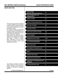
QUICK REFERENCE INDEX
BODY SECTION
This service manual has been prepared
to provide SUBARU service personnel
with the necessary information and data
for the correct maintenance and repair
of SUBARU vehicles.
This manual includes the procedures
for maintenance, disassembling, reassembling, inspection and adjustment of
components and diagnostics for guidance of experienced mechanics.
Please peruse and utilize this manual
fully to ensure complete repair work for
satisfying our customers by keeping
their vehicle in optimum condition.
When replacement of parts during
repair work is needed, be sure to use
SUBARU genuine parts.
All information, illustration and specifications contained in this manual are
based on the latest product information
available at the time of publication
approval.
FUJI HEAVY INDUSTRIES LTD.
HVAC SYSTEM
(HEATER, VENTILATOR AND A/C)
AC
HVAC SYSTEM (AUTO A/C)
(DIAGNOSTICS)
AC
AIRBAG SYSTEM
AB
AIRBAG SYSTEM (DIAGNOSTICS)
AB
SEAT BELT SYSTEM
SB
LIGHTING SYSTEM
LI
WIPER AND WASHER SYSTEMS
WW
ENTERTAINMENT
ET
COMMUNICATION SYSTEM
COM
GLASS/WINDOWS/MIRRORS
GW
BODY STRUCTURE
BS
INSTRUMENTATION/DRIVER INFO
IDI
SEATS
SE
SECURITY AND LOCKS
SL
IMMOBILIZER (DIAGNOSTICS)
IM
SUNROOF/T-TOP/CONVERTIBLE TOP
(SUNROOF)
SR
EXTERIOR/INTERIOR TRIM
EI
G1830GE6
2001 IMPREZA SERVICE MANUAL
QUICK REFERENCE INDEX
BODY SECTION
EXTERIOR BODY PANELS
EB
CRUISE CONTROL SYSTEM
CC
CRUISE CONTROL SYSTEM
(DIAGNOSTICS)
CC
G1830GE6
IMMOBILIZER (DIAGNOSTICS)
IM
1.
2.
3.
4.
5.
6.
7.
8.
9.
10.
Page
Basic Diagnostic Procedure ........................................................................2
General Description ....................................................................................3
Electrical Components Location..................................................................5
Immobilizer Control Module I/O Signal........................................................6
Subaru Select Monitor...............................................................................10
Read Diagnostic Trouble Code .................................................................12
Clear Memory Mode..................................................................................14
Diagnostics Chart for Immobilizer Indicator Light......................................16
List of Diagnostic Trouble Code (DTC) .....................................................20
Diagnostics Chart with Trouble Code........................................................21
BASIC DIAGNOSTIC PROCEDURE
IMMOBILIZER (DIAGNOSTICS)
1. Basic Diagnostic Procedure
A: PROCEDURE
Step
CHECK ILLUMINATION OF IMMOBILIZER
INDICATOR LIGHT.
Turn ignition switch ON.
CHECK ENGINE START.
Turn ignition switch to START position.
CHECK ILLUMINATION OF IMMOBILIZER
INDICATOR LIGHT.
1)Turn ignition switch to OFF or ACC position.
2)Wait at least 60 seconds.
Check
Yes
Does immobilizer indicator light Go to step 2.
illuminate?
No
Go to step 3.
Is the engine hard to start?
Go to step 3.
4
CHECK ILLUMINATION OF IMMOBILIZER
INDICATOR LIGHT.
Remove key from ignition switch.
Does immobilizer indicator light The immobilizer
bigin to blink 5 seconds after
system is OK.
the key is removed?
5
CHECK INDICATION OF DTC ON DISPLAY.
1)Turn ignition switch OFF.
2)Connect the Subaru Select Monitor to data
link connector. <Ref. to IM-10, Subaru Select
Monitor.>
3)Turn ignition switch and Subaru Select Monitor switch ON.
4)Read DTC on the display.
PERFORM THE DIAGNOSIS.
1)Inspect using “Diagnostics Chart with Trouble Code”.<Ref. to IM-21, Diagnostics Chart
with Trouble Code.>
2)Repair the trouble cause.
3)Perform clear memory mode.
4)Read DTC again.
Is trouble code indicated on
display?
Go to step 6.
Is trouble code indicated on
display?
Inspect using
“Diagnostic Chart
with Trouble
Code”. <Ref. to
IM-21, Diagnostics Chart with
Trouble Code.>
1
2
3
6
Go to step 5.
Does immobilizer indicator light Go to step 4.
blink?
IM-2
Check immobilizer
indicator light circuit.<Ref. to IM-16,
CHECK IMMOBILIZER INDICATOR CIRCUIT,
Diagnostics Chart
for Immobilizer
Indicator Light.>
Check key switch
circuit. <Ref. to IM18, CHECK KEY
SWITCH CIRCUIT, Diagnostics
Chart for Immobilizer Indicator
Light.>
Repair the related
parts.
Finish the diagnostics.
GENERAL DESCRIPTION
IMMOBILIZER (DIAGNOSTICS)
2. General Description
• When repeatedly turning ignition ON or OFF
while diagnostic items are being checked, it
should be switched in cycles of “ON” for at
least 5 seconds → “OFF” for at least 8 seconds.
A: CAUTION
CAUTION:
• Airbag system wiring harness is routed near
the immobilizer control module. All airbag system wiring harness and connectors are colored
yellow. Do not use electrical test equipment on
these circuits.
• Be careful not to damage airbag system wiring harness when servicing the immobilizer
control module.
• While diagnostic items are being checked, do
not operate radios, portable telephones, etc.
which emit electromagnetic waves near or
inside the vehicle.
B6M0618A
• If engine fails to start with a registered
ignition key, detach ignition key from ignition
switch and wait for approximately 1 second
until immobilizer indicator light begins to flash.
Start engine again.
• Before checking diagnostic items, obtain all
keys for vehicle to be checked possessed by
owner.
B6M0616
• When ignition switch is being turned ON or
OFF while diagnostic items are being checked,
do not allow keys with different ID codes close
to the ignition switch. If ignition key is in a key
holder, remove it from holder before carrying
out diagnoses.
B6M0617
IM-3
GENERAL DESCRIPTION
IMMOBILIZER (DIAGNOSTICS)
B: PREPARATION TOOL
1. SPECIAL TOOLS
ILLUSTRATION
TOOL NUMBER
22771AA030
DESCRIPTION
SELECT MONITOR
KIT
REMARKS
Troubleshooting for electrical systems.
• English:
22771AA030 (Without printer)
• German:
22771AA070 (Without printer)
• French:
22771AA080 (Without printer)
• Spanish:
22771AA090 (Without printer)
B2M3877
2. GENERAL TOOLS
TOOL NAME
Circuit Tester
REMARKS
Used for measuring resistance, voltage and ampere.
IM-4
ELECTRICAL COMPONENTS LOCATION
IMMOBILIZER (DIAGNOSTICS)
3. Electrical Components Location
A: LOCATION
BO0010
(1)
(2)
(3)
(4)
Antenna
Immobilizer indicator light (LED bulb)
Immobilizer control module (IMM ECM)
Transponder
NOTE:
IMM ECM location for RHD model is symmetrically
opposite.
IM-5
IMMOBILIZER CONTROL MODULE I/O SIGNAL
IMMOBILIZER (DIAGNOSTICS)
4. Immobilizer Control Module I/O Signal
A: SCHEMATIC
1. IMMOBILIZER LHD MODEL
FB-21
F/B FUSE NO. 11
(IG)
MB-6
M/B FUSE NO. 6
(B)
LR
BR
GR
W
W
B36
23
20
IMB(L)-01
MB-9
SBF-5
(B)
LR
IMB(L)-01
TO POWER SUPPLY ROUTING
FB-9
M/B FUSE NO. 2
(B)
LR
i1
TB : TURBO ENGINE MODEL
NA
NA : NON-TARBO ENGINE MODEL
F45
A10 LR
W
B62
KEY WARNING
SWITCH
COMBINATION
METER
A:
i10
B:
i11
W
2
WR
1
B74
BrR B6
IMMOBILIZER
INDICATOR
LIGHT
TB
RY B23
B: B135
ENGINE
CONTROL
MODULE
NA
NA
BR
i2
2
F44
YB B14
TB
B61
B: B135
NA
B37
BR
BrR
17 BrR
YB B22
RY
RY
YB
1
GR
12
6
BR
11
WR
BR
10
4
BrR
9
TB
ENGINE
CONTROL
MODULE
TB
B5
B141 IMMOBILIZER CONTROL MODULE
B74 (BLACK)
F44
1
2
1 2 3 4
5 6 7 8
F45
i2
6 7 8 9 10 11
1 2 3 4 5
12 13 14 15 16 17 18 19 20 21 22 23 24
A:
i10
(GREEN)
1 2 3
4 5
6 7 8 9 10 11 12
1 2 3 4 5 6 7 8 9 10
B: B135 : TB
B: B135 : NT
4 5 6 7
1 2 3
8 9 10 11 12 13 14 15 16 17 18 19
27 28
22 23
24 25 26
20 21
B36 (BLACK)
B141
7 8 9
1 2 3 4 5 6
10 11 12 13 14 15 16 17 18 19
23 24 25 26 27 28
20 21 22
7 8 9 10 11
1 2 3 4 5 6
12 13 14 15 16 17 18 19 20 21 22 23 24
B:
i11
(GREEN)
1 2 3 4 5 6 7
8 9 10 11 12 13 14
15 16 17 18 19 20 21 22 23 24 25 26 27 28 29 30
GL91-20A
IM-6
IMMOBILIZER CONTROL MODULE I/O SIGNAL
2
1
3
B142
B141
ANTENNA
BR
Y
BR
5
2
IMMOBILIZER CONTROL MODULE
IMB(L)-02
IMB(L)-02
IMMOBILIZER (DIAGNOSTICS)
DIODE
(WAGON)
1
24
REAR DOOR
SWITCH RH
Y
B268
B99
YR
Y
B
Y
1
3
2
FRONT DOOR
SWITCH RH
R30
REAR GATE LATCH
SWITCH (WAGON)
Y
R3
1
3
Y
B
WG
YR
4
R38
YB
B
R16
B
Y
B
BR
F76
D2 BR
B209
D35
TB
3
R22
R39
B
1
3
1
2
D46
NA
REAR DOOR
SWITCH LH
YR
D34
BR
F60
16
16
BR
SMJ
R30
D46
1
2
1 2
B99
B142
R16
1 2
R22
B268
B
REF. TO GND-02•03
BR
B
REF. TO GND-03
E3
BR
B
E3
B22
GE
GE
REF. TO GWD-04•05
D35
1 2
3 4
1
2
3
D34
B141
1 2 3
4 5 6
1 2 3
4 5
6 7 8 9 10 11 12
WG : WAGON
B22 (BROWN)
F60
1
5
9
13
2
6
10
14
3
7
11
15
(BROWN)
4
8
12
16
1 2 3 4 5
6 7 8 9 10 11
12 13 14 15 16 17 18 19 20 21 22 23 24
GL91-20B
IM-7
IMMOBILIZER CONTROL MODULE I/O SIGNAL
IMMOBILIZER (DIAGNOSTICS)
2. IMMOBILIZER RHD MODEL
MB-6
M/B FUSE NO. 6
(B)
AT
GR
W
IMB(R)-01
FB-21
F/B FUSE NO. 11
(IG)
LR
MB-9
SBF-5
(B)
BR
IMB(R)-01
TO POWER SUPPLY ROUTING
MB-10
M/B FUSE NO. 2
(B)
TB
TB : TURBO ENGINE MODEL
NA
NA : NON-TARBO ENGINE MODEL
MT
B38
3
21
B36
i3
i1
MT
A10 LR
AT
KEY WARNING
SWITCH
COMBINATION
METER
IMMOBILIZER
INDICATOR
LIGHT
A:
B:
i10
W
2
i11
WR
1
B74
BrR B6
RY B23
B: B135
ENGINE
CONTROL
MODULE
NA
TB
YG
B5
i2
B: B135
NA
B37
ENGINE
CONTROL
MODULE
TB
YG
RY B14
1
6
4
RY
WR
GR
BR
BR
10
11
12
BrR
TB
9
BrR
22
BrR
NA
YG B22
B141 IMMOBILIZER CONTROL MODULE
B74 (BLACK)
1
2
A:
i10
(GREEN)
1 2 3 4 5 6 7 8 9 10
B: B135 : TB
7 8 9
1 2 3 4 5 6
10 11 12 13 14 15 16 17 18 19
23 24 25 26 27 28
20 21 22
B:
(BLACK)
B141
i1
i3
1 2 3
4 5
6 7 8 9 10 11 12
1 2 3
4 5 6
7 8 9 10 11 12 13 14
1 2 3 4 5
6 7 8 9 10
11 12 13 14 15 16 17 18 19 20 21 22
i11
(GREEN)
1 2 3 4 5 6 7
8 9 10 11 12 13 14
15 16 17 18 19 20 21 22 23 24 25 26 27 28 29 30
B: B135 : NT
4 5 6 7
1 2 3
8 9 10 11 12 13 14 15 16 17 18 19
27 28
24 25 26
22 23
20 21
i2
5 6 7 8
1 2 3 4
10 11 12 13 14 15 16 17 18 19 20 21
22 23 24 25 26 27 28 29 30 31 32
GR91-20A
IM-8
IMMOBILIZER CONTROL MODULE I/O SIGNAL
2
1
3
B142
B141
ANTENNA
GW
Y
GW
5
2
IMMOBILIZER CONTROL MODULE
IMB(R)-02
IMB(R)-02
IMMOBILIZER (DIAGNOSTICS)
DIODE
(WAGON)
1
Y
B268
R30
4
B99
YR
Y
B
Y
1
3
2
FRONT DOOR
SWITCH LH
REAR DOOR
SWITCH RH
REAR GATE LATCH
SWITCH (WAGON)
Y
R3
1
3
Y
B
WG
YR
4
R38
Y
B
R30
1 2
1 2
B22
B
R39
B
BR
B
REF. TO GND-02•03
GE
REF. TO GND-04•05
B99
1
2
B
D35
WG : WAGON
REF. TO GND-03
D46 (BLACK)
3
E3
B
R22
B142
1
2
D46
16 GW
1
3
YB
B
D34
R16
BR
REAR DOOR
SWITCH LH
YR
R16
D35
D34
B141
R22
1 2
3 4
1 2 3
4 5 6
1 2 3
4 5
6 7 8 9 10 11 12
B268
1
2
3
B22 (BROWN)
1
5
9
13
2
6
10
14
3
7
11
15
4
8
12
16
1 2 3 4 5
6 7 8 9 10 11
12 13 14 15 16 17 18 19 20 21 22 23 24
GR91-20B
IM-9
SUBARU SELECT MONITOR
IMMOBILIZER (DIAGNOSTICS)
5. Subaru Select Monitor
5) Turn ignition switch to ON (engine OFF) and
Subaru Select Monitor switch to ON.
A: OPERATION
1. HOW TO USE SUBARU SELECT MONITOR
1) Prepare Subaru Select Monitor kit.
S2M0288A
6) Using Subaru Select Monitor, call up diagnostic
trouble code(s) and various data, then record them.
2. READ DIAGNOSTIC TROUBLE CODE
(DTC) FOR ENGINE.
S2M0285
2) Connect diagnosis cable to Subaru Select Monitor.
3) Insert cartridge into Subaru Select Monitor.
Refer to Read Diagnostic Trouble Code for information about how to indicate DTC. <Ref. to IM-12,
Read Diagnostic Trouble Code.>
3. INTERFACE CHECK
NOTE:
Communication line between ECM and IMM ECM
can be checked in «System Operation Check
Mode». This is referred to as “interface check”.
1) Connect select monitor.
2) Set the «System Operation Check Mode» menu
display screen then select «Immobilizer System».
3) Screen indicates as shown.
S2M0286A
4) Connect Subaru Select Monitor to data link connector.
(1) Data link connector located in the lower portion of the instrument panel (on the driver's
side).
S6M0210
EN0768
(2) Connect diagnosis cable to data link connector.
CAUTION:
Do not connect scan tools except for Subaru
Select Monitor.
IM-10
SUBARU SELECT MONITOR
IMMOBILIZER (DIAGNOSTICS)
4) Start interface check.
5) Does “Communication Line not Shorted” appear
on screen?
If “YES”. Go to step 6).
If “NO”. Go to step 7).
S6M0211
6) After diagnostic results, it is determined that
short circuit is not a diagnostic item. This completes
interface check.
7) If a problem is detected, repair. <Ref. to IM-22,
DTC P1572 — IMM CIRCUIT FAILURE (EXCEPT
ANTENNA CIRCUIT) —, Diagnostics Chart with
Trouble Code.>
IM-11
READ DIAGNOSTIC TROUBLE CODE
IMMOBILIZER (DIAGNOSTICS)
6. Read Diagnostic Trouble Code
A: OPERATION
1. WITH SUBARU SELECT MONITOR
1) On the «Main Menu» display screen, select the {Each System Check} and press the [YES] key.
2) On the «System Selection Menu» display screen, select the {Engine Control System} and press the [YES]
key.
3) Press the [YES] key after displayed the information of engine type.
4) On the «Engine Diagnosis» display screen, select the {Diagnostic Code(s) Display} and press the [YES]
key.
5) On the «Diagnostic Code(s) Display» display screen, select the {Current Diagnostic Code(s)} or {History
Diagnostic Code(s)} and press the [YES] key.
NOTE:
• For detailed operation procedure, refer to the SUBARU SELECT MONITOR OPERATION MANUAL.
• For detailed concerning diagnostic trouble codes, refer to the List of Diagnostic Trouble Code (DTC). <Ref.
to IM-20, LIST, List of Diagnostic Trouble Code (DTC).>
2. WITHOUT SUBARU SELECT MONITOR
1
2
Step
Check
CHECK STATUS OF CHECK ENGINE MAL- Does the MIL come on?
FUNCTION INDICATOR LAMP (MIL).
1)Turn ignition switch to OFF.
2)Connect read memory connector. <Ref. to
EN(SOHCw/oOBD)-10, LOCATION, Electrical
Components Location.>
3)Turn ignition switch to ON.
CHECK DIAGNOSTIC TROUBLE CODE
(DTC).
Yes
Go to step 2.
No
Check the following and repair if
necessary.
NOTE:
• Open or short
circuit in engine
control module
power supply or
ground line
• Open or short
circuit in CHECK
ENGINE malfunction indicator lamp
Does the MIL indicate diagnos- Record diagnostic Complete read
diagnostic trouble
tic trouble code (DTC)?
trouble code
(DTC). Then turn code. Turn ignition
switch to OFF and
ignition switch to
disconnect read
OFF, disconnect
read memory con- memory connecnector.
tor.
IM-12
READ DIAGNOSTIC TROUBLE CODE
IMMOBILIZER (DIAGNOSTICS)
The CHECK ENGINE malfunction indicator lamp (MIL) flashes the code corresponding to the faulty parts.
The long segment (1.3 seconds ON) indicates a “ten”, and the short segment (0.2 seconds ON) signifies
“one”. And middle segment (0.5 seconds ON) means OK code.
• For detailed concerning diagnostic trouble codes, refer to the List of Diagnostic Trouble Code (DTC). <Ref.
to IM-20, LIST, List of Diagnostic Trouble Code (DTC).>
S2M1768A
IM-13
CLEAR MEMORY MODE
IMMOBILIZER (DIAGNOSTICS)
7. Clear Memory Mode
A: OPERATION
1. WITH SUBARU SELECT MONITOR
1) On the «Main Menu» display screen, select the {2. Each System Check} and press the [YES] key.
2) On the «System Selection Menu» display screen, select the {Engine Control System} and press the [YES]
key.
3) Press the [YES] key after displayed the information of engine type.
4) On the «Engine Diagnosis» display screen, select the {Clear Memory} and press the [YES] key.
5) When the `Done' and `Turn Ignition Switch OFF' are shown on the display screen, turn the Subaru Select
Monitor and ignition switch to OFF.
NOTE:
• After the memory has been cleared, the ISC must be initialized. To do this, turn the ignition switch to the
ON position. Wait 3 seconds before starting the engine.
• For detailed operation procedure, refer to the SUBARU SELECT MONITOR OPERATION MANUAL.
2. WITHOUT SUBARU SELECT MONITOR
1
2
Step
Check
CHECK STATUS OF CHECK ENGINE MAL- Does the MIL come on?
FUNCTION INDICATOR LAMP (MIL).
1)Turn ignition switch to OFF.
2)Set shift lever to neutral position (MT vehicles), or set selector lever to “P” position (AT
vehicles).
3)Connect test mode connector and read
memory connector.
4)Turn ignition switch to ON.
Yes
Go to step 2.
No
Check the following and repair if
necessary.
NOTE:
• Open or short
circuit in engine
control module
power supply or
ground line
• Open or short
circuit in CHECK
ENGINE malfunction indicator lamp
Does the MIL indicate diagnos- Record diagnostic Turn ignition switch
CHECK DIAGNOSTIC TROUBLE CODE
tic trouble code (DTC)? <Ref. trouble code.
to OFF. Disconnect
(DTC).
to IM-20, LIST, List of Diagnos- Repair the trouble read memory con1)Set selector lever to “N” position, and then
cause.
nector and test
set selector lever to “P” position again (AT vehi- tic Trouble Code (DTC).>
mode connector.
cles only).
Complete clear
2)Start the engine.
memory mode.
3)Drive vehicle at speed greater than 11 km/h
(7 MPH) for at least one minute.
4)Warm-up engine above 2,000 rpm.
IM-14
CLEAR MEMORY MODE
IMMOBILIZER (DIAGNOSTICS)
IM-15
DIAGNOSTICS CHART FOR IMMOBILIZER INDICATOR LIGHT
IMMOBILIZER (DIAGNOSTICS)
8. Diagnostics Chart for Immobilizer Indicator Light
A: INSPECTION
1. CHECK IMMOBILIZER INDICATOR CIRCUIT
WIRING DIAGRAM:
BATTERY
M/B No.2
SBF-1
IGNITION
SWITCH
LHD
F/B No.11
SBF-4
RHD
SBF-5
3
20
B36
B36
i1
RHD
i1
LHD
COMBINATION METER
A:
LHD : LHD MODEL
i10
B:
i11
IMMOBILIZER
INDICATOR
LIGHT
RHD : RHD MODEL
1 : LHD MODEL: 17
A10
: RHD MODEL: 22
B6
1
i2
9
12
11
3
10
2
B37
B141 IMMOBILIZER CONTROL MODULE
E
B141
i1
1 2 3
4 5
6 7 8 9 10 11 12
1 2 3
4 5 6
7 8 9 10 11 12 13 14
RHD
A:
i10
1 2 3 4 5 6 7 8 9 10
B:
i11
1 2 3 4 5 6 7
8 9 10 11 12 13 14
15 16 17 18 19 20 21 22 23 24 25 26 27 28 29 30
i2
LHD
B36
i2
1 2 3 4 5
6 7 8 9 10 11
12 13 14 15 16 17 18 19 20 21 22 23 24
1 2 3 4
5 6 7 8 9
10 11 12 13 14 15 16 17 18 19 20 21
22 23 24 25 26 27 28 29 30 31 32
RHD
BO0149
IM-16
DIAGNOSTICS CHART FOR IMMOBILIZER INDICATOR LIGHT
IMMOBILIZER (DIAGNOSTICS)
1
2
3
4
5
6
Step
CHECK IMMOBILIZER INDICATOR LIGHT
COMES ON.
1)Turn ignition switch OFF.
2)Disconnect harness connector from IMM
ECM.
3)Connect a resistor (750 Ω) between IMM
ECM harness connector terminal No. 9 and
chassis ground.
CHECK IMM ECM GROUND CIRCUIT.
Measure resistance between IMM ECM harness connector terminal and chassis ground.
Connector & terminal
(B141) No. 2, No. 3 (+) — Chassis ground
(−):
CHECK IMM ECM IGNITION CIRCUIT.
1)Turn ignition switch ON. (Engine OFF.)
2)Measure voltage between IMM ECM harness connector terminal and chassis ground.
Connector & terminal
(B141) No. 12 (+) — Chassis ground (−):
CHECK IMM ECM POWER SUPPLY CIRCUIT.
1)Turn ignition switch OFF.
2)Measure voltage between IMM ECM harness connector terminal and chassis ground.
Connector & terminal
(B141) No. 10, No. 11 (+) — Chassis
ground (−):
Check
Yes
Does indicator light comes on? Go to step 2.
No
Go to step 5.
Is the resistance less than 10
Ω?
Go to step 3.
Repair open circuit
of IMM ECM
ground circuit.
Is the voltage more than 10 V? Go to step 4..
Check harness for
open or short
between IMM
ECM and ignition
switch.
Is the voltage more than 10 V? Replace IMM ECM
<Ref. to SL-44,
Immobilizer Control Module.> and
then replace all
ignition keys
(including the transponder). Then
perform teaching
operation. Refer to
teaching operation manual (Pub.
No. S0820GZ).
Is the voltage more than 10 V? Go to step 6.
Check harness for
open or short
between IMM
ECM and fuse.
CHECK COMBINATION METER CIRCUIT.
1)Remove combination meter. <Ref. to IDI-19,
Combination Meter Assembly.>
2)Measure voltage between combination
meter harness connector terminal and chassis
ground.
Connector & terminal
(i10) No. 10 (+) — Chassis ground (−):
Is the resistance less than 10
CHECK COMBINATION METER CIRCUIT.
Measure resistance between IMM ECM harΩ?
ness connector terminal and combination
meter harness connector terminal.
Connector & terminal
(B141) No. 9 — (i11) No. 6:
IM-17
Check harness for
open or short
between combination meter and
fuse.
Faulty LED bulb.
Repair harness or
Replace combina- connector.
tion meter printed
circuit. <Ref. to
IDI-20, DISASSEMBLY, Combination Meter
Assembly.>
DIAGNOSTICS CHART FOR IMMOBILIZER INDICATOR LIGHT
IMMOBILIZER (DIAGNOSTICS)
2. CHECK KEY SWITCH CIRCUIT
WIRING DIAGRAM:
BATTERY
M/B No.6
RHD
LHD
23
F45
RHD
B62
LHD
LHD : LHD MODEL
RHD : RHD MODEL
KEY WARNING
SWITCH
2
1
4
B74
B141
IMMOBILIZER
CONTROL
MODULE
B74
B141
F45
1
2
1 2 3
4 5
6 7 8 9 10 11 12
6 7 8 9 10 11
1 2 3 4 5
12 13 14 15 16 17 18 19 20 21 22 23 24
BO0150
IM-18
DIAGNOSTICS CHART FOR IMMOBILIZER INDICATOR LIGHT
IMMOBILIZER (DIAGNOSTICS)
1
2
3
4
Step
CHECK POWER SUPPLY CIRCUIT.
1)Disconnect harness connector from key
warning switch.
2)Turn ignition switch ACC or LOCK position
(The key inserted).
3)Measure voltage between key warning
switch harness connector terminal and chassis
ground.
Connector & terminal
(B74) No. 2 (+) — Chassis ground (−):
CHECK KEY SWITCH.
1)Insert the ignition key to the ignition switch.
(OFF or ACC position)
2)Check continuity between key warning
switch connector terminals.
Connector & terminal
No. 1 — No. 2:
CHECK KEY SWITCH.
1)Remove the ignition key from the ignition
switch.
2)Check continuity between key warning
switch connector terminals.
Connector & terminal
No. 1 — No. 2:
CHECK HARNESS BETWEEN KEY SWITCH
AND IMM ECM.
1)Disconnect harness connector from key
warning switch.
2)Disconnect harness connector from IMM
ECM.
3)Measure resistance between key warning
switch harness connector terminal and IMM
ECM harness connector terminal.
Connector & terminal
(B74) No. 1 — (B141) No. 4:
Check
Yes
Is the voltage more than 10 V? Go to step 2.
No
Check harness for
open or short
between key warning switch and
fuse.
Dose continuity exist?
Go to step 3.
Replace key warning switch.
Does continuity exsit?
Replace key warn- Go to step 4.
ing switch.
Is the resistance less than 10
Ω?
Replace IMM ECM
<Ref. to SL-44,
Immobilizer Control Module.> and
then replace all
ignition keys
(including the transponder). Then
perform teaching
operation. Refer to
teaching operation manual (Pub.
No. S0820GZ).
IM-19
Repair harness
between key warning switch and
IMM ECM.
LIST OF DIAGNOSTIC TROUBLE CODE (DTC)
IMMOBILIZER (DIAGNOSTICS)
9. List of Diagnostic Trouble Code (DTC)
A: LIST
DTC
Without
With
OBD
OBD
53
Item
Contents of diagnosis
P1571
Reference Code Incompatibility
Reference code incompatibility
between IMM ECM and ECM
P1572
IMM Circuit Failure
(Except Antenna Circuit)
Communication failure between
IMM ECM and ECM
P1574
Key Communication Failure
Failure of IMM ECM to verify key
(transponder) ID code
P0153
Use of Unregistered Key
Incorrect immobilizer key (Use of
unregistered key in IMM ECM)
P1576
EGI Control Module
EEPROM
ECM malfunctioning
P1577
IMM Control Module
EEPROM
IMM ECM malfunctioning
P1570
ANTENNA
Faulty antenna
Index No.
<Ref. to IM-21, DTC P1571 — REFERENCE CODE INCOMPATIBILITY —,
Diagnostics Chart with Trouble Code.>
<Ref. to IM-22, DTC P1572 — IMM CIRCUIT FAILURE (EXCEPT ANTENNA
CIRCUIT) —, Diagnostics Chart with
Trouble Code.>
<Ref. to IM-26, DTC P1574 — KEY
COMMUNICATION FAILURE —, Diagnostics Chart with Trouble Code.>
<Ref. to IM-27, DTC P0153 — INCORRECT IMMOBILIZER KEY (USE OF
UNREGISTERED KEY) —, Diagnostics
Chart with Trouble Code.>
<Ref. to IM-27, DTC P1576 — EGI CONTROL MODULE EEPROM —, Diagnostics Chart with Trouble Code.>
<Ref. to IM-27, DTC P1577 — IMM
CONTROL MODULE EEPROM —,
Diagnostics Chart with Trouble Code.>
<Ref. to IM-28, DTC P1570 —
ANTENNA —, Diagnostics Chart with
Trouble Code.>
NOTE:
• When reading diagnostic trouble code except with SUBARU SELECT MONITOR, the item cannot be specified. Therefore diagnose for all items.
• When a diagnostic trouble code except for the above immobilizer trouble code has been output, carry out
diagnosis for the engine trouble code. <Ref. to EN(SOHC)-81, List of Diagnostic Trouble Code (DTC).> or
<Ref. to EN(SOHCw/oOBD)-66, List of Diagnostic Trouble Code (DTC).> or <Ref. to EN(DOHC TURBO)-69,
List of Diagnostic Trouble Code (DTC).>
IM-20
DIAGNOSTICS CHART WITH TROUBLE CODE
IMMOBILIZER (DIAGNOSTICS)
10.Diagnostics Chart with Trouble Code
A: DTC P1571 — REFERENCE CODE INCOMPATIBILITY —
DIAGNOSIS:
• Reference code incompatibility between IMM ECM and ECM
1
Step
Check
PERFORM TEACHING OPERATION ON IG- Is teaching operation for all
keys completed?
NITION KEY.
Perform teaching operation on all keys of the
vehicle. Refer to teaching operation manual.
IM-21
Yes
END
No
Replace ECM
<Ref. to
FU(SOHC)-48,
Engine Control
Module.>, <Ref. to
FU(SOHCw/
oOBD)-44, Engine
Control Module.>
or <Ref. to
FU(DOHC
TURBO)-45,
Engine Control
Module.>, IMM
ECM <Ref. to SL44, Immobilizer
Control Module.>
and then replace
all ignition keys
(including the transponder). Then
perform teaching
operation. Refer to
teaching operation manual (Pub.
No. S0820GZ).
DIAGNOSTICS CHART WITH TROUBLE CODE
IMMOBILIZER (DIAGNOSTICS)
B: DTC P1572 — IMM CIRCUIT FAILURE (EXCEPT ANTENNA CIRCUIT) —
DIAGNOSIS:
• Communication failure between IMM ECM and ECM
WIRING DIAGRAM:
IGNITION
SWITCH
BATTERY
SBF-1
F/B No.11
SBF-4
SBF-5
TB : TURBO ENGINE MODEL
NA : NON-TURBO ENGINE MODEL
1 : LHD MODEL: B23
: RHD MODEL: B22
2 : LHD MODEL: B22
: RHD MODEL: B23
3 : LHD MODEL: B5
: RHD MODEL: B14
4 : LHD MODEL: B14
: RHD MODEL: B5
TB
NA
B: B135
ENGINE
CONTROL
MODULE
B: B135
B: B135
NA
4 5 6 7
1 2 3
8 9 10 11 12 13 14 15 16 17 18 19
24 25 26
20 21
27 28
22 23
ENGINE
CONTROL
MODULE
B: B135
12
11
6
10
1
3
2
4
3
2
1
TB
NA
B141 IMMOBILIZER CONTROL MODULE
E
TB
1 2 3 4 5 6
7 8 9
10 11 12 13 14 15 16 17 18 19
23 24 25 26 27 28
20 21 22
B141
1 2 3
4 5
6 7 8 9 10 11 12
BO0151
IM-22
DIAGNOSTICS CHART WITH TROUBLE CODE
IMMOBILIZER (DIAGNOSTICS)
1
2
3
4
5
Step
CHECK POWER SUPPLY CIRCUIT OF IMM
ECM.
1)Turn ignition switch OFF.
2)Disconnect harness connector from IMM
ECM.
3)Measure voltage between IMM ECM harness connector terminal and chassis ground.
Connector & terminal
(B141) No. 10, No.11 (+) — Chassis
ground (−):
CHECK POWER SUPPLY CIRCUIT OF IMM
ECM.
1)Turn ignition switch ON. (Engine OFF.)
2)Measure voltage between IMM ECM harness connector terminal and chassis ground.
Connector & terminal
(B141) No. 12 (+) — Chassis ground (−):
CHECK GROUND CIRCUIT OF IMM ECM.
1)Turn ignition switch OFF.
2)Measure resistance between IMM ECM harness connector terminal and chassis ground.
Connector & terminal
(B141) No. 2, No.3 (+) — Chassis ground
(−):
CHECK HARNESS BETWEEN IMM ECM
AND ECM.
1)Disconnect harness connector from ECM
and IMM ECM.
2)Measure resistance between IMM ECM harness connector terminal and ECM harness
connector terminal.
Connector & terminal
LHD non-turbo engine model:
(B141) No. 1 — (B135) No. 22:
RHD non-turbo engine model:
(B141) No. 1 — (B135) No. 23:
LHD turbo engine model:
(B141) No. 1 — (B135) No. 14:
RHD turbo engine model:
(B141) No. 1 — (B135) No. 5:
CHECK HARNESS BETWEEN IMM ECM
AND ECM.
Measure resistance between IMM ECM harness connector terminal and ECM harness
connector terminal.
Connector & terminal
LHD non-turbo engine model:
(B141) No. 6 — (B135) No. 23:
RHD non-turbo engine model:
(B141) No. 6 — (B135) No. 22:
LHD turbo engine model:
(B141) No. 6 — (B135) No. 5:
RHD non-turbo engine model:
(B141) No. 6 — (B135) No. 14:
Check
Yes
Is the voltage more than 10 V? Go to step 2.
No
Check harness for
open or short
between IMM
ECM and fuse.
Is the voltage more than 10 V? Go to step 3.
Check harness for
open or short
between IMM
ECM and ignition
switch.
Is the resistance less than 10
Ω?
Go to step 4.
Repair open circuit
of IMM ECM
ground circuit.
Is the resistance less than 10
Ω?
Go to step 5.
Repair open circuit
of harness
between IMM
ECM and ECM.
Is the resistance less than 10
Ω?
Go to step 6.
Repair open circuit
of harness
between IMM
ECM and ECM.
IM-23
DIAGNOSTICS CHART WITH TROUBLE CODE
IMMOBILIZER (DIAGNOSTICS)
6
7
8
9
Step
CHECK HARNESS OF COMMUNICATION
LINE.
1)Turn ignition switch ON. (Engine OFF.)
2)Measure voltage between IMM ECM harness connector terminal and chassis ground.
Connector & terminal
(B141) No. 1, No.6 (+) — Chassis ground
(−):
CHECK HARNESS OF COMMUNICATION
LINE.
Measure voltage between ECM harness connector terminal and engine ground.
Connector & terminal
Non-turbo engine model:
(B135) No. 22, No.23 (+) — Engine
ground (−):
Turbo engine model:
(B135) No. 5, No.14 (+) — Engine
ground (−):
CHECK ECM BY INTERFACE CHECK.
1)Connect harness connector to ECM.
2)Disconnect harness connector from IMM
ECM.
3)Perform interface check. <Ref. to IM-10,
INTERFACE CHECK, Subaru Select Monitor.>
CHECK ECM BY INTERFACE CHECK.
Perform interface check.
Check
Is the voltage 0 V?
Yes
Go to step 7.
Is the voltage 0 V?
Go to step 8.
No
Repair harness
between IMM
ECM and ECM,
because there is
short circuit in battery voltage line or
ignition switch
“ON” line.
Repair harness
between IMM
ECM and ECM,
because there is
short circuit in battery voltage line or
ignition switch
“ON” line.
Does “Commun. Line Shorted Replace ECM.
Go to step 9.
to Ground” appear on screen? <Ref. to
FU(SOHC)-48,
Engine Control
Module.>, <Ref. to
FU(SOHCw/
oOBD)-44, Engine
Control Module.>
or <Ref. to
FU(DOHC
TURBO)-45,
Engine Control
Module.> Then
perform teaching
operation. Refer to
teaching operation manual (Pub.
No. S0820GZ).
Go to step 10.
Does “Commun. Line Shorted Replace ECM.
to Battery” appear on screen? <Ref. to
FU(SOHC)-48,
Engine Control
Module.>, <Ref. to
FU(SOHCw/
oOBD)-44, Engine
Control Module.>
or <Ref. to
FU(DOHC
TURBO)-45,
Engine Control
Module.> Then
perform teaching
operation. Refer to
teaching operation manual (Pub.
No. S0820GZ).
IM-24
DIAGNOSTICS CHART WITH TROUBLE CODE
IMMOBILIZER (DIAGNOSTICS)
10
Step
CHECK ECM BY INTERFACE CHECK.
Perform interface check.
Check
Yes
Does “Communication Line not Replace IMM ECM
Shorted” appear on screen?
<Ref. to SL-44,
Immobilizer Control Module.> and
then replace all
ignition keys
(including the transponder). Then
perform teaching
operation. Refer to
teaching operation manual (Pub.
No. S0820GZ).
IM-25
No
When “Check
(Time Out)”
appears on
screen, perform
interface check
again.
DIAGNOSTICS CHART WITH TROUBLE CODE
IMMOBILIZER (DIAGNOSTICS)
C: DTC P1574 — KEY COMMUNICATION FAILURE —
DIAGNOSIS:
• Failure of IMM ECM to verify key (transponder) ID code
1
2
Step
CHECK IMM ECM FUNCTION.
Insert the key to ignition switch (LOCK position), measure changes in voltage between
Antenna connector.
Connector & terminal
(B142) No. 1 — No. 2:
Check
Yes
Is the voltage −30 to 30 V?
Go to step 2.
(Approximately 0.1 second
after inserting the key.) Is the
voltage 0 V? (Approximately 1
second after inserting the key.)
CHECK IGNITION KEY (TRANSPONDER).
1)Remove the key from ignition switch.
2)Start engine using other keys that have
undergone the teaching operation, furnished
with vehicle.
Does engine start?
IM-26
Replace ignition
key (including the
transponder).
Then perform
teaching operation. Refer to
teaching operation manual (Pub.
No. S0820GZ).
No
Replace IMM ECM
<Ref. to SL-44,
Immobilizer Control Module.> and
then replace all
ignition keys
(including the transponder). Then
perform teaching
operation. Refer to
teaching operation manual (Pub.
No. S0820GZ).
Replace IMM ECM
<Ref. to SL-44,
Immobilizer Control Module.> and
then replace all
ignition keys
(including the transponder). Then
perform teaching
operation. Refer to
teaching operation manual (Pub.
No. S0820GZ).
DIAGNOSTICS CHART WITH TROUBLE CODE
IMMOBILIZER (DIAGNOSTICS)
D: DTC P0153 — INCORRECT IMMOBILIZER KEY (USE OF UNREGISTERED
KEY) —
DIAGNOSIS:
• Use of unregistered key in IMM ECM
1
2
Step
PERFORM TEACHING OPERATION ON IGNITION KEY.
Perform teaching operation on all keys of the
vehicle. Refer to teaching operation manual
(Pub. No. S0820GZ).
PERFORM TEACHING OPERATION ON IGNITION KEY.
Perform teaching operation on all keys with
vehicle. Refer to teaching operation manual
(Pub. No. S0820GZ).
Check
Is teaching operation for all
keys completed?
Is teaching operation for all
keys completed?
Yes
END
END
No
Replace all ignition
keys (including the
transponder). Go
to step 2.
Replace IMM ECM
<Ref. to SL-44,
Immobilizer Control Module.> and
then replace all
ignition keys
(including the transponder). Then
perform teaching
operation. Refer to
teaching operation manual (Pub.
No. S0820GZ).
E: DTC P1576 — EGI CONTROL MODULE EEPROM —
DIAGNOSIS:
• ECM malfunctioning
1. REPLACE ECM.
Replace ECM.
<Ref. to FU(SOHC)-48, Engine Control Module.>, <Ref. to FU(SOHCw/oOBD)-44, Engine Control Module.>
or <Ref. to FU(DOHC TURBO)-45, Engine Control Module.>
Then perform teaching operation. Refer to teaching operation manual (Pub. No. S0820GZ).
F: DTC P1577 — IMM CONTROL MODULE EEPROM —
DIAGNOSIS:
• IMM ECM malfunctioning
1. REPLACE IMM ECM.
Replace IMM ECM <Ref. to SL-44, Immobilizer Control Module.> and then replace all ignition keys (including the transponder). Then perform teaching operation. Refer to teaching operation manual (Pub. No.
S0820GZ).
IM-27
DIAGNOSTICS CHART WITH TROUBLE CODE
IMMOBILIZER (DIAGNOSTICS)
G: DTC P1570 — ANTENNA —
DIAGNOSIS:
• Faulty antenna
WIRING DIAGRAM:
B6M1534
IM-28
DIAGNOSTICS CHART WITH TROUBLE CODE
IMMOBILIZER (DIAGNOSTICS)
Step
CHECK ANTENNA CIRCUIT.
1)Turn ignition switch OFF.
2)Disconnect harness antenna connector from
IMM ECM. <Ref. to SL-45, Immobilizer
Antenna.>
3)Measure resistance of antenna circuit.
Connector & terminal
(B142) No. 1 — No. 2:
CHECK ANTENNA CIRCUIT.
Measure resistance between antenna harness
connector and chassis ground.
Connector & terminal
(B142) No. 1 (+) — Chassis ground (−):
CHECK ANTENNA CIRCUIT.
Measure resistance between antenna harness
connector and chassis ground.
Connector & terminal
(B142) No. 2 (+) — Chassis ground (−):
CHECK ANTENNA CIRCUIT.
1)Turn ignition switch ON. (Engine OFF.)
2)Measure voltage between antenna harness
connector and chassis ground.
Connector & terminal
(B142) No. 1 (+) — Chassis ground (−):
CHECK ANTENNA CIRCUIT.
Measure voltage between antenna harness
connector and chassis ground.
Connector & terminal
(B142) No. 2 (+) — Chassis ground (−):
Check
Is the resistance less than 10
Ω?
Yes
Go to step 2.
Is the resistance less than 10
Ω?
Replace antenna. Go to step 3.
<Ref. to SL-45,
Immobilizer
Antenna.>
Is the resistance less than 10
Ω?
Replace antenna. Go to step 4.
<Ref. to SL-45,
Immobilizer
Antenna.>
Is the voltage 0 V?
Go to step 5.
Replace antenna.
<Ref. to SL-45,
Immobilizer
Antenna.>
Is the voltage 0 V?
Go to step 6.
6
CHECK IMM ECM FUNCTION.
1)Turn ignition switch OFF.
2)Connect antenna harness connector to IMM
ECM.
3)Insert the key to ignition switch, measure
changes in voltage between antenna harness
connector.
Connector & terminal
(B142) No. 1 — No. 2:
Is the voltage −30 to 30 V?
Go to step 7.
(Approximately 0.1 second
after inserting the key.) Is the
voltage 0 V? (Approximately 1
second after inserting the key.)
7
CHECK IGNITION KEY (TRANSPONDER).
1)Remove key from ignition switch.
2)Start engine using other keys that have
undergone the teaching operation, furnished
with vehicle.
Does engine start?
Repair harness
between IMM
ECM and antenna,
because there is
short circuit in battery voltage line or
ignition switch
“ON” line.
Replace IMM ECM
<Ref. to SL-44,
Immobilizer Control Module.> and
then replace all
ignition keys
(including the transponder). Then
perform teaching
operation. Refer to
teaching operation manual (Pub.
No. S0820GZ).
Replace IMM ECM
<Ref. to SL-44,
Immobilizer Control Module.> and
then replace all
ignition keys
(including the transponder). Then
perform teaching
operation. Refer to
teaching operation manual (Pub.
No. S0820GZ).
1
2
3
4
5
IM-29
Replace ignition
key (including the
transponder).
Then perform
teaching operation. Refer to
teaching operation manual (Pub.
No. S0820GZ).
No
Replace antenna.
<Ref. to SL-45,
Immobilizer
Antenna.>
DIAGNOSTICS CHART WITH TROUBLE CODE
IMMOBILIZER (DIAGNOSTICS)
IM-30