1
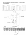
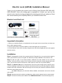
Electric Lock (LM148) Installation Manual
Thank you for purchasing the electric lock for Sliding Gate Operator DSC 600/1000,
DSR 600/1000. Once your sliding gate is separated to 2 parts, you can use the
electric lock to lock the moving part against the standing part with your pleasure. Read
the manual carefully and completely before you install the electric lock.
Electric Lock Part List
Important Information
1. Before you install the Electric Lock please be sure the gate is level, moves freely, and does not
bind or block against barriers.
2. The lock and receiver could be installed on either slide gate with your pleasure.
3. For the Electric Lock to work correctly, the gate must close firmly engage the lock catch against
the lock receiver.
Installation
Step 1: Disengage the clutch of the operator with the Triangular Key, you can moves the gate by
hand, ensure both two parts of the gate can slide freely during installation of the Electric Lock.
Step 2: With the gate in the closed position, determine the best location for the lock and
receiver. The lock and the socket of the receiver must be Horizontal Centers aligned with each
other. The lock and receiver should have a solid surface or tube fence to provide stability.
Step 3: For Metallic Tube gate, if the thickness of the fence post is larger than or equal to 3mm,
you can threading on the fence post, fasten the lock and receiver only use bolts (Figure B. Without
washers and nuts). Otherwise, drill holes through out the fence post, fasten the lock and receiver
with bolts, lock washers and nuts.
For Chain Link gate, you will need U-Bolts, saddles, lock washers and nuts for the lock
and receiver.
Step 4: Recheck the lock’s position and alignment, make sure the electric lock to work correctly.
Step 5: Connect the lock’s power cables to the DSR/DSC 600/1000 ’s control board (Figure C).
1
Note: Be sure that the clutch of the operator is engaged before you prepare to activate it.
(Use the Triangular Key)
Figure A
Figure B
Figure C
2