1
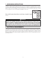
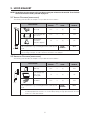
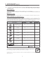
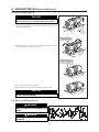
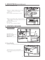
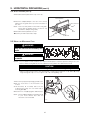
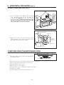
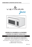
INSTALLATION INSTRUCTIONS
MB0001
MODELS VJ10430SS & VJ10430WH
!
INTENDED FOR DOMESTIC COOKING ONLY
!
READ AND SAVE THESE INSTRUCTIONS
INSTALLER: LEAVE THIS GUIDE WITH HOMEOWNER.
Venmar Ventilation inc., 550 Lemire Blvd., Drummondville QC J2C 7W9
1-800-567-3855
For additional information - visit www.venmar.ca
08816 rev. A
IMPORTANT SAFETY INSTRUCTIONS
!
WARNING
!
TO REDUCE THE RISK OF FIRE, ELECTRIC SHOCK OR
INJURY TO PERSONS, OBSERVE THE FOLLOWING:
WARNING
TO REDUCE THE RISK OF INJURY TO PERSONS IN
THE EVENT OF A RANGE TOP GREASE FIRE, OBSERVE
THE FOLLOWING*:
1. Use this unit only in the manner intended by the
manufacturer. If you have questions, contact the
manufacturer at the address or telephone number listed
in the warranty.
2. Before servicing or cleaning unit, switch power off at
service panel and lock service disconnecting means
to prevent power from being switched on accidentally.
When the service disconnecting means cannot be
locked, securely fasten a prominent warning device,
such as a tag, to the service panel.
3. Installation work and electrical wiring must be done by
qualified personnel in accordance with all applicable
codes and standards, including fire-rated construction
codes and standards.
4. Sufficient air is needed for proper combustion and
exhausting of gases through the flue (chimney) of fuel
burning equipment to prevent backdrafting. Follow the
heating equipment manufacturer’s guidelines and safety
standards such as those published by the National Fire
Protection Association (NFPA) and the American Society
for Heating, Refrigeration and Air Conditioning Engineers
(ASHRAE) and the local code authorities.
5. When cutting or drilling into wall or ceiling, do not damage
electrical wiring and other hidden utilities.
6. Ducted fans must always be vented to the outdoors.
7. Do not use this unit with any other solid-state speed
control device.
8. To reduce the risk of fire, use only metal ductwork.
9. The mounting surface must be capable of supporting
the cabinet load, in addition to the added weight of this
46-pound product, plus additional oven loads of up to
50 pounds for a total weight of 96 pounds.
10.This product cannot be installed in cabinet arrangements
such as an island or a peninsula. It must be mounted to
BOTH a top cabinet AND the wall behind the product.
11.Do not mount over a sink.
12.This unit must be grounded. To provide protection
against electric shock, connect to properly grounded
outlets only.
13.When applicable local regulations comprise more
restrictive installation and/or certification requirements,
the aforementioned requirements prevail on those of this
document and the installer agrees to conform to these at
his own expenses.
1. SMOTHER FLAMES with a close-fitting lid, cookie sheet
or metal tray, then turn off the burner. BE CAREFUL
TO PREVENT BURNS. IF THE FLAMES DO NOT GO
OUT IMMEDIATELY, EVACUATE AND CALL THE FIRE
DEPARTMENT.
2. NEVER PICK UP A FLAMING PAN — You may be
burned.
3. DO NOT USE WATER, including wet dishcloths or towels
— This could cause a violent steam explosion.
4. Use an extinguisher ONLY if:
A. You own a Class ABC extinguisher and you know how
to operate it.
B. The fire is small and contained in the area where it
started.
C. The fire department has been called.
D. You can fight the fire with your back to an exit.
*Based on “Kitchen Fire Safety Tips” published by NFPA.
CAUTION
1. For indoor use only.
2. For general ventilating use only. Do not use to exhaust
hazardous or explosive materials and vapors.
3. To avoid motor bearing damage and noisy and/or
unbalanced impellers, keep drywall spray, construction
dust, etc. off power unit.
4. Your hood motor has a thermal overload which will
automatically shut off the motor if it becomes overheated.
The motor will restart when it cools down. If the motor
continues to shut off and restart, have the hood serviced.
5. Ensure the product meets the minimum ventilation
requirements specified by the range manufacturer.
6. Two installers are recommended because of the weight
of this unit.
7. To reduce the risk of fire, do not exhaust air into spaces
within walls, ceiling, attics, crawl space or garage.
8. This product is equipped with a thermostat which may
start blower automatically. To reduce the risk of injury and
to prevent power from being switched on accidentally,
unplug the unit power cord or switch power off at service
panel and lock or tag service panel.
TO REDUCE THE RISK OF A RANGE TOP GREASE FIRE:
9. Because of the high exhausting capacity of this unit, you
should make sure enough air is entering the house to
replace exhausted air by opening a window close to or in
the kitchen.
a) Never leave surface units unattended at high settings.
Boilovers cause smoking and greasy spillovers that may
ignite. Heat oils slowly on low or medium settings.
b) Always turn hood ON when cooking at high heat or when
flambeing food (i.e.: Crêpes Suzette, Cherries Jubilee,
Peppercorn Beef Flambé).
c) Clean ventilating fans frequently. Grease should not be
allowed to accumulate on fan or filter.
d) Use proper pan size. Always use cookware appropriate
for the size of the surface element.
10.Please read specification label on product for further
information and requirements.
2
IMPORTANT SAFETY INSTRUCTIONS
FOR INSTALLATION OVER A GAS RANGE
CAUTION (GAS RANGE)
1.
2.
3.
4.
5.
6.
The minimum distances given in this installation guide must be observed in order to ensure safe operation.
The microwave oven should only be installed in a well ventilated area.
The unit must NOT be installed in recirculation (non-ducted).
This microwave oven is intended for use over gas range of 50,000 BTU/hr. maximum.
Ensure the product meets the minimum ventilation requirements specified by the range manufacturer.
The microwave oven should only be installed as illustrated below, while maintaining the required safety distances. Do
not install the microwave oven between two tall cabinets.
RECOMMENDED
NOT RECOMMENDED
NOT ALLOWED
MH0004
TABLE OF CONTENTS
1. GROUNDING INSTRUCTIONS ................... 4
2. ELECTRICAL REQUIREMENTS ................. 4
3. HOOD EXHAUST ......................................... 5
3.1
3.2
8.1
8.2
8.3
8.4
8.5
Vertical Discharge ..........................................5
Horizontal Discharge ......................................5
4. PREPARE THE INSTALLATION .................. 7
4.1
4.2
4.3
8. NON-DUCTED (RECIRCULATION)............. 14
9. HORIZONTAL DISCHARGE ........................ 18
Included Parts ...............................................7
Needed Tools ................................................7
Mounting Space ............................................8
9.1
9.2
9.3
9.4
9.5
5. PLACEMENT OF THE MOUNTING PLATE ..8
5.1
5.2
5.3
5.4
Prepare Rear Wall ..........................................18
Attach Mounting Plate to the Wall ..................19
Prepare Top Cabinet ......................................19
Adjust Blower ................................................19
Mount the Microwave Oven ...........................21
Removing Microwave Oven from Carton/
Removing Mounting Plate ..............................8 10. BEFORE USING
Finding the Wall Studs ...................................9
THE MICROWAVE OVEN ............................ 22
Determining Mounting Plate Location.............9
Aligning the Mounting Plate ...........................10
6. SELECT INSTALLATION TYPE ................... 11
7. VERTICAL DISCHARGE .............................. 11
7.1
7.2
7.3
7.4
7.5
Attach Mounting Plate to the Wall ..................15
Prepare Top Cabinet ......................................15
Adjust Blower ................................................15
Mount the Microwave Oven ...........................16
Install the Charcoal Filter ................................18
Attach Mounting Plate to the Wall ..................12
Prepare Top Cabinet ......................................12
Install Adapter/Damper ..................................12
Mount the Microwave Oven ...........................13
Connecting Ductwork ....................................14
3
1. GROUNDING INSTRUCTIONS
This appliance requires a three-prong grounded outlet. In the event of an electrical short circuit, grounding reduces the risk
of electric shock by providing an escape wire for the electrical current. This appliance is equipped with a power cord having
a grounding wire with a grounding plug. The plug must be plugged into an outlet that is properly installed and grounded. No
adapter should be used with this appliance. Plug the three-prong power cord into a properly grounded outlet of standard
115-120 voltage, 60 Hz. Your oven should be the only appliance on this circuit.
Where a standard two-prong wall receptacle is encountered, it is very important to have
it replaced with a properly grounded three-prong wall receptacle, installed by a qualified
electrician.
MD0003
! WARNING
Improper use of the grounding plug can result in a risk of electric shock. Consult a qualified
electrician if the grounding instructions are not completely understood, or if doubt exists as to
whether the appliance is properly grounded. Do not use an extension cord. If the power supply
cord is too short, have a qualified electrician install an outlet near the appliance, in accordance
with all applicable codes and standards. Do not cut, deform or remove the third (ground) prong
from the power cord under any circumstances. Connect the unit only to a 20 A dedicated circuit.
2. ELECTRICAL REQUIREMENTS
Product rating is 120 volts AC, 60 Hertz, 13.5 amps and 1.5 kilowatts. This product must be connected to a supply circuit
of the proper voltage and frequency. Wire size must conform to the requirements of the National Electrical Code or the
prevailing local code for this power rating. The power supply cord and plug should be brought to a separate 20-ampere
branch circuit single grounded outlet. The outlet box should be located in the cabinet above the microwave oven. The
outlet box and supply circuit should be installed by a qualified electrician and conform to the National Electrical Code or
the prevailing local code.
4
3. HOOD EXHAUST
NOTE: Read these next two pages only if you plan to vent your exhaust to the outside. To recirculate
the air back into the room, proceed to page 14.
3.1 VERTICAL DISCHARGE (EXAMPLE ONLY)
The following chart describes an example of one possible ductwork installation.
EQUIVALENT
LENGTH
X
NUMBER
USED
=
EQUIVALENT
LENGTH
Roof cap
24 ft.
x
(1)
=
24 ft.
12 Ft. Straight duct
(6” round)
12 ft.
x
(1)
=
12 ft.
Rectangularto-Round
Transition adapter*
5 ft.
x
(1)
=
5 ft.
TOTAL
LENGTH
=
41 ft.
DUCT PIECES
MR0002
Equivalent lengths of duct pieces are based on actual tests and
reflect requirements for good venting performance with any vent
hood.
*If a rectangular-to-round transition adapter is used, the bottom corners of the damper will have to be
cut to fit, using a tin snips, in order to allow free movement of the damper.
3.2 HORIZONTAL DISCHARGE (EXAMPLE ONLY)
The following chart describes an example of one possible ductwork installation.
EQUIVALENT
LENGTH
X
NUMBER
USED
=
EQUIVALENT
LENGTH
Wall cap
40 ft.
x
(1)
=
40 ft.
3 Ft. Straight duct
(3¼” x 10”
rectangular)
3 ft.
x
(1)
=
3 ft.
90˚ Elbow
10 ft.
x
(2)
=
20 ft.
TOTAL
LENGTH
=
63 ft.
DUCT PIECES
MR0003
Equivalent lengths of duct pieces are based on actual tests and
reflect requirements for good venting performance with any vent
hood.
NOTE: For back exhaust, care should be taken to align exhaust with space between studs, or wall
should be prepared at the time it is constructed by leaving enough space between the wall
studs to accommodate exhaust.
5
3. HOOD EXHAUST (CONT’D)
Outside ventilation requires a HOOD EXHAUST DUCT. Read the following carefully.
NOTE: It is important that venting be installed using the most direct route and with as few elbows as possible. This ensures
clear venting of exhaust and helps prevent blockages. Also, ensure damper swings freely and nothing is
blocking the ducts.
EXHAUST CONNECTION:
The hood exhaust has been designed to mate with a standard 3¼” x 10” rectangular duct.
If a round duct is required, a rectangular-to-round transition adapter must be used. Do not use less than a 6”
diameter duct.
MAXIMUM DUCT LENGTH:
For satisfactory air movement, the total duct length of 3¼” x 10” rectangular or 6” diameter round duct should not
exceed 140 equivalent feet.
ELBOWS, TRANSITIONS, WALL AND ROOF CAPS, ETC.
These duct pieces present additional resistance to airflow and are equivalent to a section of straight duct which
is longer than their actual physical size. When calculating the total duct length, add the equivalent lengths of all
transitions and adapters plus the length of all straight duct sections. The chart below shows you how to calculate
total equivalent ductwork length using the approximate feet of equivalent length of some typical ducts.
EQUIVALENT
LENGTH
X
NUMBER
USED
=
EQUIVALENT
LENGTH
Rectangular-to-round
transition adapter*
5 ft.
x
( )
=
ft.
Wall cap
40 ft.
x
( )
=
ft.
90˚ Elbow
10 ft.
x
( )
=
ft.
45˚ Elbow
5 ft.
x
( )
=
ft.
90˚ Elbow
25 ft.
x
( )
=
ft.
45˚ Elbow
5 ft.
x
( )
=
ft.
Roof cap
24 ft.
x
( )
=
ft.
Straight duct 3¼” x 10”
rectangular or 6” round
1 ft.
x
( )
=
ft.
TOTAL
DUCTWORK
=
ft.
DUCT PIECES
MR0004
*If a rectangular-to-round transition adapter is used, the bottom corners of the damper will have to
be cut to fit, using a tin snips, in order to allow free movement of the damper.
MR0005
Equivalent lengths of duct pieces are based on actual tests and reflect requirements for good venting performance
with any vent hood.
6
4. PREPARE THE INSTALLATION
! WARNING
When performing installation, servicing or cleaning the unit, it is recommended to wear safety
glasses and gloves.
4.1 INCLUDED PARTS
Ensure that the following parts are included:
DESCRIPTION
PART
NO.
QTY.
1
Top cabinet template
08824
1
2
Rear wall template
08825
1
3
Installation guide
08816
1
4
User guide
08817
1
5
Grease filter
08821
1
6
Charcoal filter
08820
1
NO.
7
Adapter/Damper
08822
1
8
Turntable
08818
1
9
Roller guide ring
08819
1
10
Parts bag including:
1 Wood screw 1/4” x 2” (A),
2 Toggle bolts 3/16” x 3” (B),
2 Self-aligning machine
screws 1/4”-28 x 3¼” (C),
1 Nylon strip
for metal cabinets (D)
(to use as grommet)
2
4
3
1
5
6
8
7
9
MA0010
10
08823
1
A
B
C
D
MR0006
4.2 NEEDED TOOLS
No. 1 and no. 2
Phillips screwdriver
Pencil
Ruler or tape measure
and straight edge
Tin snips (to cut
damper if required)
Scissors (to cut
template, if necessary)
Safety gloves
Saw
(saber, hole or keyhole)
Electric drill with 3/16”,
1/2” and 5/8” drill bits
Stud finder
or hammer
MR0008
Metal foil duct tape and tape
Level
7
Carpenter square
(optional)
Safety goggles
Filler blocks or scrap
wood if needed for top
cabinet spacing (used on
recessed bottom cabinet
installations only)
4. PREPARE THE INSTALLATION (CONT’D)
4.3 MOUNTING SPACE
! WARNING
The mounting surface must be able to support the
cabinet load, in addition to the added weight of this
46 lb. product, plus additional oven loads of up to
50 lb. for a total weight of 96 lb.
16½”
MINIMUM DISTANCE
TO COOKTOP*
• The space between the cabinets must be at least 30” wide and
free of obstructions.
• This microwave oven is for installation over ranges up to 36” wide.
• If you are going to vent your microwave oven to the outside, see
“Select Installation Type” Section on page 11 for exhaust duct
preparation.
• When installing the microwave oven, be careful to follow the
instructions on the top cabinet template for power cord clearance.
*Electric range: 30”
Gas range: 36½”
MH0001A
5. PLACEMENT OF THE MOUNTING PLATE
5.1 REMOVING MICROWAVE OVEN FROM CARTON/REMOVING MOUNTING PLATE
CARTON
1. Remove the adapter/damper, filters, turntable,
roller guide ring and parts bag. Do not remove
the polystyrene protecting the front of the oven.
2. Fold back all 4 carton flaps fully against carton
sides. Then carefully roll the oven and carton over
onto the top side. The oven should be resting in
the polystyrene.
3. Pull the carton up and off the oven.
POLYSTYRENE
MR0009A
4. Remove and properly discard plastic bags.
SCREW
SCREW
MOUNTING PLATE
5. Remove the 2 mounting plate retaining screws
and discard. Set the mounting plate aside.
MO0011A
8
5. PLACEMENT OF THE MOUNTING PLATE (CONT’D)
5.2 FINDING THE WALL STUDS
1. Find the studs using one of the following methods:
A. Stud finder.
OR
B. Use a hammer to tap lightly across the mounting
surface to find a solid sound. This will indicate a stud
location.
2. After locating the stud(s), find the center by probing the
wall with a small nail to find the edges of the stud. Then
place a mark halfway between the edges. The center of
any adjacent studs should be 16” or 24” from this mark.
WALL STUDS
CENTER
3. Draw a line down the center of each stud.
NOTE: The microwave oven must be connected to at
least one wall stud.
MR0010A
5.3 DETERMINING MOUNTING PLATE LOCATION
Your cabinets may have decorative trim that interferes with the microwave installation. Remove the decorative trim to
install the microwave properly and to make it level.
NOTE: The microwave oven must be level.
PLATE POSITION BENEATH FLAT BOTTOM CABINET
FLAT BOTTOM CABINET
1. Draw a vertical line on the wall at the center of the 30”
minimum wide space.
2. Tape the rear wall template onto the wall matching the
centerline and touching the bottom of the cabinet.
*Electric range: 30”
Gas range: 36½”
MINIMUM DISTANCE TO COOKTOP*
MD0004A
PLATE POSITION BENEATH FRAMED RECESSED
BOTTOM CABINET
FRAMED RECESSED BOTTOM CABINET
1. Draw a vertical line on the wall at the center of the 30”
minimum wide space.
2. Tape the rear wall template onto the wall matching the
centerline and touching the bottom cabinet frame.
*Electric range: 30”
Gas range: 36½”
MINIMUM DISTANCE TO COOKTOP*
MD0005A
9
5. PLACEMENT OF THE MOUNTING PLATE (CONT’D)
5.3 DETERMINING MOUNTING PLATE LOCATION (CONT’D)
PLATE POSITION BENEATH RECESSED
BOTTOM CABINET WITH FRONT OVERHANG
RECESSED BOTTOM CABINET
WITH FRONT OVERHANG
DRAW A HORIZONTAL LINE
1. Measure the inside depth of the front
overhang.
ON THE BACK WALL
EQUAL TO THE DEPTH
OF THE FRONT OVERHANG.
2. Draw a horizontal line on the back wall an
equal distance below the cabinet bottom as
the inside depth of the front overhang.
3. Draw a vertical line on the wall at the center
of the 30” minimum wide space.
4. Align the top of the rear wall template with
the horizontal line and tape it onto the wall
matching the centerline.
*Electric range: 30”
Gas range: 36½”
MINIMUM DISTANCE
TO COOKTOP*
MD0006A
5.4 ALIGNING THE MOUNTING PLATE
! WARNING
Wear safety gloves as the edges of the mounting plate are sharp.
CENTERLINE
A
NOTCH
CL
HORIZONTAL LINE
AREA E
DRAW A HORIZONTAL LINE
C
B
HORIZONTAL LINE
ON WALL FROM BOTTOM OF
THE REAR WALL TEMPLATE
MD0007A
1. Draw a horizontal line on the wall at the bottom of the rear wall template.
2. Drill 5/8” holes for toggle bolts on 3 locations (Hole A, B, C) but if the location of hole is same as that of stud, drill
a 3/16” hole for wood screw. In other words, toggle bolt can not be used to the location of stud. Do not mount
the plate at this time.
NOTE: Holes A, B and C are inside area E. If none of A, B or C is in a stud, find a stud somewhere in area E and
draw a fourth circle to line up with the stud. It is important to use at least one wood screw mounted firmly in
a stud to support the weight of the microwave oven. Set the mounting plate aside.
10
6. SELECT INSTALLATION TYPE
The microwave oven is designed for adaptation to the following three types of ventilation:
Vertical discharge (Section 7).
Non-ducted (Recirculation) (Section 8).
MF0002
MF0001
Horizontal discharge (Section 9).
MF0003
7. VERTICAL DISCHARGE
INSTALLATION OVERVIEW
7.1
7.2
7.3
7.4
7.5
Attach mounting plate to wall
Prepare top cabinet
Install Adapter/damper
Mount the microwave oven
Connect ductwork
MH0002
11
7. VERTICAL DISCHARGE (CONT’D)
7.1 ATTACH THE MOUNTING PLATE TO THE WALL
Attach the plate to the wall using toggle bolts. At least one wood screw must be used to attach the plate to a wall stud.
1. Remove the rear wall template and discard.
2. Remove the toggle wings from the bolts.
3. Insert the bolts into the mounting plate through the holes
designated to go into drywall and reattach the toggle
wings to 3/4” onto each bolt.
MO0012
4. Place the bottom of the mounting plate against the
horizontal line on the wall (previously drawn in step 5.4 )
and insert the toggle wings into the holes in the wall to
mount the plate.
SPACING FOR TOGGLES
MORE THAN WALL THICKNESS
TOGGLE WINGS
TOGGLE
MOUNTING
PLATE
BOLT
5. Tighten the wood screw and all bolts.
! WARNING
Be careful to avoid pinching fingers between
the back of the mounting plate and the wall.
WALL
BOLT END
MO0013A
7.2 PREPARE TOP CABINET
You need to drill holes for the top support screws, a hole large enough for the power cord to fit through and a cutout
large enough for the adapter/damper.
! WARNING
Wear safety goggles when drilling holes in the
cabinet bottom.
1. Read the instructions on the top cabinet template.
2. Tape it underneath the top cabinet.
3. Drill the holes following the instructions on the template.
4. Remove the template and discard.
MR0011
7.3 INSTALL ADAPTER/DAMPER
1. Slide adapter/damper as shown beside.
NOTE: Ensure that the damper hinge is oriented toward the
back of the microwave oven.
2. Ensure tape securing damper is removed and damper
pivots easily before mouting microwave oven.
MO0014
12
7. VERTICAL DISCHARGE (CONT’D)
7.4 MOUNT THE MICROWAVE OVEN
! WARNING
For easier installation and personal
safety, this unit must be installed by two
people.
! WARNING
Do not grip or use door handle during
installation.
MO0015
NOTES: • If your cabinet is metal, install the nylon strip around the power cord hole to prevent cutting of the cord.
• We recommend using filler blocks if the cabinet front hangs below the cabinet bottom shelf.
CAUTION
If filler blocks are not used, case damage may occur from over tightening screws.
• When mounting the microwave oven, thread power cord through hole in bottom of top cabinet (A). Keep
it tight throughout steps 1-3. Do not pinch cord or lift oven by pulling cord.
A
1. Remove the polystyrene packaging and discard.
2. Lift microwave, tilt it forward, and hook slots
at back bottom edge onto four lower tabs of
mounting plate (B).
3. Rotate front of oven (C) up against cabinet bottom.
C
B
MO0016
D
3. Insert 2 self-aligning screws (D) through top
cabinet holes. Temporarily secure the oven by
turning the screws at least 2 full turns on each
screw after the threads have engaged. Ensure
to keep power cord tight. Be careful not to
pinch the cord, especially when mounting
flush to bottom of cabinet.
MO0018
13
7. VERTICAL DISCHARGE (CONT’D)
7.4 MOUNT THE MICROWAVE OVEN (CONT’D)
CABINET FRONT
CABINET BOTTOM SHELF
FILLER BLOCK
4. Tighten the 2 screws to the top of the microwave oven.
(While tightening screws, hold the microwave oven in
place against the wall and the top cabinet.)
EQUIVALENT
TO DEPTH OF
CABINET RECESS
SELF-ALIGNING SCREW
MO0017A
MICROWAVE OVEN TOP
7.5 CONNECT DUCTWORK
HOUSE DUCT
1. Extend the house duct down to connect to the
adapter/damper.
NOTE: Ensure adapter/damper is properly inserted
in your house exhaust duct.
2. Seal the joint with metal foil duct tape.
3. Proceed to step 10 to finalize the installation.
MJ0001A
8. NON-DUCTED (RECIRCULATION)
INSTALLATION OVERVIEW
8.1
8.2
8.3
8.4
8.5
Attach mounting plate to wall
Prepare top cabinet
Adjust blower
Mount the microwave oven
Install charcoal filter
NOTE: The
adapter/damper
is not needed for a
non-ducted installation,
but it may be saved for
possible future use.
MH0003
14
8. NON-DUCTED (RECIRCULATION) (CONT’D)
8.1 ATTACH THE MOUNTING PLATE TO THE WALL
Attach the plate to the wall using toggle bolts. At least one wood screw must be used to attach the plate to a wall stud.
1. Remove the rear wall template and discard.
2. Remove the toggle wings from the bolts.
3. Insert the bolts into the mounting plate through the holes
designated to go into drywall and reattach the toggle
wings to 3/4” onto each bolt.
MO0012
4. Place the bottom of the mounting plate against the
horizontal line on the wall (previously drawn in step 5.4 )
and insert the toggle wings into the holes in the wall to
mount the plate.
SPACING FOR TOGGLES
MORE THAN WALL THICKNESS
TOGGLE WINGS
TOGGLE
MOUNTING
PLATE
BOLT
5. Tighten the wood screw and all bolts.
! WARNING
Be careful to avoid pinching fingers between
the back of the mounting plate and the wall.
WALL
BOLT END
MO0013A
8.2 PREPARE TOP CABINET
You need to drill holes for the top support screws and a hole large enough for the power cord to fit through.
! WARNING
Wear safety goggles when drilling holes in the
cabinet bottom.
1. Read the instructions on the top cabinet template.
2. Tape it underneath the top cabinet.
3. Drill the holes following the instructions on the template.
4. Remove the template and discard.
MR0011
8.3 ADJUST BLOWER
BLOWER PLATE
1. Remove and set aside the 2 blower plate retaining
screws.
2. Lift up the blower plate.
SCREW
MICROWAVE TOP
MICROWAVE BACK
MD0008A
15
SCREW
8. NON-DUCTED (RECIRCULATION) (CONT’D)
8.3 ADJUST BLOWER (CONT’D)
CAUTION
Do not touch the blower blades to prevent cracks and
breaks. Hold outer case when handling the blower.
3. Remove and set aside the blower motor retaining screw. Carefully
pull out the blower unit. The wires will extend far enough to allow
blower unit adjustment.
BLOWER
MOTOR
RETAINING
SCREW
BEFORE: FAN BLADE
OPENINGS FACING UP
4. Roll the blower unit 90˚ so that fan blade openings are facing
toward the front of the microwave oven.
AFTER: FAN BLADE
OPENINGS FACING FRONT
5. Install the blower unit back in place.
6. Secure blower unit to microwave with its retaining screw.
CAUTION
Do not pull or stretch the blower unit wiring. Ensure
the wires are not pinched.
8.4 MOUNT THE MICROWAVE OVEN
! WARNING
For easier installation and personal
safety, this unit must be installed by two
people.
! WARNING
Do not grip or use door handle during
installation.
MO0015
16
MD0010A
8. NON-DUCTED (RECIRCULATION) (CONT’D)
8.4 MOUNT THE MICROWAVE OVEN (CONT’D)
NOTES: • If your cabinet is metal, install the nylon strip around the power cord hole to prevent cutting of the cord.
• We recommend using filler blocks if the cabinet front hangs below the cabinet bottom shelf.
CAUTION
If filler blocks are not used, case damage may occur from over tightening screws.
• When mounting the microwave oven, thread power cord through hole in bottom of top cabinet (A). Keep
it tight throughout steps 1-3. Do not pinch cord or lift oven by pulling cord.
A
1. Remove the polystyrene packaging and discard.
2. Lift microwave, tilt it forward, and hook slots
at back bottom edge onto four lower tabs of
mounting plate (B).
3. Rotate front of oven (C) up against cabinet bottom.
C
B
MO0016
D
3. Insert 2 self-aligning screws (D) through top cabinet
holes. Temporarily secure the oven by turning the screws
at least 2 full turns on each screw after the threads
have engaged. Ensure to keep power cord tight.
Be careful not to pinch the cord, especially when
mounting flush to bottom of cabinet.
MO0018
CABINET FRONT
CABINET BOTTOM SHELF
FILLER BLOCK
4. Tighten the 2 screws to the top of the microwave oven.
(While tightening screws, hold the microwave oven in
place against the wall and the top cabinet.)
EQUIVALENT
TO DEPTH OF
CABINET RECESS
SELF-ALIGNING SCREW
MO0017A
17
MICROWAVE OVEN TOP
8. NON-DUCTED (RECIRCULATION) (CONT’D)
8.5 INSTALL THE CHARCOAL FILTER
CHARCOAL
FILTER
1. Using a no. 2 Phillips screwdriver, remove the 3 grille
retaining screws (located on top of the grille).
2. Open the door.
3. Push the grille left, then pull straight out to remove.
MO0021A
4. Slide the charcoal filter into place. The filter should rest at the
angle shown beside. When properly installed, the wire mesh of
the filter is visible.
5. Reinstall the grille and its screws.
6. Close the door.
7. Proceed to step 10 to finalize the installation.
MO0022
9. HORIZONTAL DISCHARGE
INSTALLATION OVERVIEW
9.1
9.2
9.3
9.4
9.5
Prepare rear wall
Attach mounting plate to wall
Prepare top cabinet
Adjust blower
Mount the microwave oven
MH0002
9.1 PREPARE REAR WALL
You need to cut an opening in the rear wall for horizontal discharge.
1. Read the instructions on the rear wall template.
2. Cut the opening, following the instructions on the rear
wall template.
MD0012
18
9. HORIZONTAL DISCHARGE (CONT’D)
9.2 ATTACH THE MOUNTING PLATE TO THE WALL
Attach the plate to the wall using toggle bolts. At least one wood screw must be used to attach the plate to a wall stud.
1. Remove the rear wall template and discard.
2. Remove the toggle wings from the bolts.
3. Insert the bolts into the mounting plate through the holes
designated to go into drywall and reattach the toggle
wings to 3/4” onto each bolt.
MO0012
4. Place the bottom of the mounting plate against the
horizontal line on the wall (previously drawn in step 5.4 )
and insert the toggle wings into the holes in the wall to
mount the plate.
SPACING FOR TOGGLES
MORE THAN WALL THICKNESS
TOGGLE WINGS
TOGGLE
MOUNTING
PLATE
BOLT
5. Tighten the wood screw and all bolts.
! WARNING
Be careful to avoid pinching fingers between
the back of the mounting plate and the wall.
WALL
BOLT END
MO0013A
9.3 PREPARE TOP CABINET
You need to drill holes for the top support screws and a hole large enough for the power cord to fit through.
! WARNING
Wear safety goggles when drilling holes in the
cabinet bottom.
1. Read the instructions on the top cabinet template.
2. Tape it underneath the top cabinet.
3. Drill the holes following the instructions on the template.
4. Remove the template and discard.
MR0011
9.4 ADJUST BLOWER
BLOWER PLATE
1. Remove and set aside the 2 blower plate retaining
screws.
2. Lift up the blower plate.
SCREW
MICROWAVE TOP
MICROWAVE BACK
MD0008A
19
SCREW
9. HORIZONTAL DISCHARGE (CONT’D)
9.4 ADJUST BLOWER (CONT’D)
CAUTION
Do not touch the blower blades to prevent cracks and
breaks. Hold outer case when handling the blower.
BEFORE: FAN BLADE
OPENINGS FACING UP
3. Remove and set aside the blower motor retaining screw. Carefully
pull out the blower unit. The wires will extend far enough to allow
blower unit adjustment.
BLOWER
MOTOR
RETAINING
SCREW
4. Roll the blower unit 90˚ so that fan blade openings are facing
toward the front of the microwave oven.
END B
5. Flip blower unit 180˚, so that the fan blade openings are facing
toward the back of the microwave oven.
END A
END A
END B
AFTER: FAN BLADE
OPENINGS FACING BACK
6. Install the blower unit back in place.
7. Secure blower unit to microwave with its retaining screw.
MD0014A
CAUTION
Do not pull or stretch the blower unit wiring. Ensure the wires are not pinched.
NOTE: The blower unit exhaust openings should match exhaust openings on rear of microwave oven.
20
9. HORIZONTAL DISCHARGE (CONT’D)
9.4 ADJUST BLOWER (CONT’D)
7. Reinstall the blower plate with its top screw only.
ADAPTER/DAMPER
8. Attach the adapter/damper to the rear of the oven by
sliding it into the guides at the top center of the back of
the oven.
MICROWAVE BACK
NOTE: Push in securely until it is in the lower locking tabs.
Ensure that the damper hinge is located on top
and that the damper swings freely.
GUIDE
9. Reinstall the blower plate back screw.
10.Seal the joint with metal foil duct tape.
GUIDE
LOCKING TABS
MD0015A
9.5 MOUNT THE MICROWAVE OVEN
! WARNING
For easier installation and personal
safety, this unit must be installed by two
people.
! WARNING
Do not grip or use door handle during
installation.
MO0015
NOTES: • If your cabinet is metal, install the nylon strip around the power cord hole to prevent cutting of the cord.
• We recommend using filler blocks if the cabinet front hangs below the cabinet bottom shelf.
CAUTION
If filler blocks are not used, case damage may occur from over tightening screws.
• When mounting the microwave oven, thread power cord through hole in bottom of top cabinet (A). Keep
it tight throughout steps 1-3. Do not pinch cord or lift oven by pulling cord.
A
1. Remove the polystyrene packaging and discard.
2. Run the house duct to the microwave oven
location.
3. Lift microwave, tilt it forward, and hook slots
at back bottom edge onto four lower tabs of
mounting plate (B).
4. Rotate front of oven (C) up against cabinet bottom.
NOTE: Ensure adapter/damper is properly inserted
in your house exhaust duct after the
microwave oven is installed.
C
B
MO0016
21
9. HORIZONTAL DISCHARGE (CONT’D)
9.5 MOUNT THE MICROWAVE OVEN (CONT’D)
D
3. Insert 2 self-aligning screws (D) through top cabinet
holes. Temporarily secure the oven by turning the
screws at least 2 full turns on each screw after the
threads have engaged. Ensure to keep power cord
tight. Be careful not to pinch the cord, especially
when mounting flush to bottom of cabinet.
MO0018
CABINET FRONT
CABINET BOTTOM SHELF
FILLER BLOCK
4. Tighten the 2 screws to the top of the microwave oven.
(While tightening screws, hold the microwave oven in
place against the wall and the top cabinet.)
EQUIVALENT
TO DEPTH OF
CABINET RECESS
SELF-ALIGNING SCREW
MO0017A
MICROWAVE OVEN TOP
10. BEFORE USING THE MICROWAVE OVEN
1. Install grease filter. See the Owner’s manual packed with
the microwave oven.
MO0019
2. Ensure the microwave oven has been installed according to instructions.
3. Remove all packing material from the microwave oven.
4. Install turntable and ring in cavity.
5. Switch power on at service panel.
6. Plug unit power cord into a dedicated 20-amp electrical outlet.
7. Read Owner’s manual.
8. Keep installation intructions for the local inspector’s use.
22