1
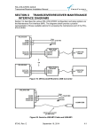
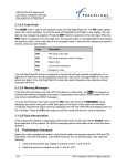
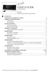
XPLORER ADS-B Receiver
Installation Manual
EQUIPMENT INSTALLATION MANUAL
For the
FreeFlight Systems
XPLORER ADS-B Receiver (P/N 87099-XX)
Document No: 87214 Revision A
FreeFlight Systems
3700 Interstate 35 S.
Waco, TX 76706
This document contains FreeFlight Systems proprietary information. It is loaned for limited purposes only and
remains the property of FreeFlight Systems. It may not be reproduced in whole or in part without written consent of
FreeFlight Systems and must not be disclosed to persons not having need of such disclosure consistent with the
purpose of the loan. The document is to be returned to FreeFlight Systems upon request and/or upon completion of
the use for which it was loaned.
XPLORER ADS-B Receiver
Installation Manual
History of Revisions
Dates of Original and Change pages are:
Revision
Page Description
87214, Revision A
….. A ……………
December 3. 2012
Page no.
December 3, 2012
Date
XPLORER ADS-B Receiver
Installation Manual
Table of Contents
SECTION I
GENERAL INFORMATION ..................................................................... I-1
1.1
INTRODUCTION ............................................................................................. I-1
1.2
SYSTEM DESCRIPTION ................................................................................ I-1
1.2.1
General Description ..................................................................................... I-1
1.2.2
XPLORER CONFIGURATIONS .................................................................. I-1
1.2.3
Example Configurations .............................................................................. I-2
1.2.4
GPS Usage.................................................................................................. I-3
1.3
XPLORER INSTALLATION OVERVIEW ........................................................ I-4
1.3.1
Connectors .................................................................................................. I-4
1.3.2
Status Lights ................................................................................................ I-4
1.4
UAT ANTENNA REQUIREMENTS ................................................................. I-5
1.5
Technical Characteristics ................................................................................ I-6
1.6
PARTS AND EQUIPMENT ............................................................................. I-7
1.6.1
XPLORER Receiver Items .......................................................................... I-7
1.6.2
Installation Kits ............................................................................................ I-7
1.7
MATERIALS REQUIRED BUT NOT SUPPLIED............................................. I-8
1.7.1
Required ...................................................................................................... I-8
1.7.2
Optional ....................................................................................................... I-8
SECTION II
INSTALLATION ...................................................................................... II-1
2.1
GENERAL ...................................................................................................... II-1
2.2
UNPACKING AND INSPECTING EQUIPMENT ............................................ II-1
2.3
EQUIPMENT MOUNTING ............................................................................. II-1
2.3.1
XPLORER Mounting................................................................................... II-1
2.4
COOLING REQUIREMENTS ......................................................................... II-1
2.5
XPLORER ELECTRICAL CONNECTIONS ................................................... II-2
2.5.1
2.6
XPLORER INTERFACE – PINOUT ........................................................... II-2
XPLORER INTERFACE DETAILS ................................................................. II-2
2.6.1
Power Input ................................................................................................ II-2
2.6.2
Serial Interfaces (RS-232 Version Only) .................................................... II-2
2.6.3
Time Mark Input (PPS) ............................................................................... II-3
2.6.4
Maintenance Interface (RS-232 Version Only) ........................................... II-3
2.6.5
Status LEDs................................................................................................ II-3
2.7
UAT ANTENNA INSTALLATION ................................................................... II-4
87214, Revision A
December 3, 2012
XPLORER ADS-B Receiver
Installation Manual
2.7.1
UAT Antenna Ground Plane ....................................................................... II-5
2.7.2
UAT Antenna Cable.................................................................................... II-5
2.8
EQUIPMENT LIMITATIONS .......................................................................... II-6
SECTION III
CONFIGURATION AND CHECKOUT ............................................... III-1
3.1
GENERAL ..................................................................................................... III-1
3.2
ENABLING TRAFFIC OUTPUT (TIS-B) ........................................................ III-1
3.3
PRELIMINARY CHECKOUT ......................................................................... III-1
3.4
SETUP AND CONFIGURATION (RS-232 VERSION ONLY) ....................... III-2
3.4.1
Maintenance Commands........................................................................... III-2
SECTION IV
4.1
XPLORER LED TROUBLSHOOTING PROCEDURE.................................. IV-1
SECTION V
5.1
TROUBLESHOOTING...................................................................... IV-1
INSTALLATION DRAWINGS ................................................................ V-1
XPLORER RECEIVER DIMENSIONS .......................................................... V-1
SECTION VI
TYPICAL INTERCONNECT DIAGRAMS ......................................... VI-1
6.1
XPLORER INTERCONNECT WITH WI-FI ONLY ........................................ VI-1
6.2
XPLORER INTERCONNECT WITH RS-232 AND EXTERNAL GPS .......... VI-2
6.2.1
XPLORER INTERCONNECT WITH RS-232 AND INTERNAL GPS ....... VI-3
SECTION VII
XPLORER (RS-232 VERSION ONLY) MAINTENANCE ADAPTER VII-1
SECTION VIII
WARNING DISCLAIMER ............................................................... VIII-1
SECTION IX
LIMITED WARRANTY ...................................................................... IX-2
Table of Figures
Figure 1: Typical XPLORER Installation with Display-connected GPS........................... I-2
Figure 2: XPLORER with RS232-connected Uncertified Cockpit Display ....................... I-2
Figure 3: XPLORER with Uncertified Display and Internal GPS Unit ............................. I-3
Figure 4: XPLORER Receiver with WiFi Option ............................................................. I-4
Figure 5: XPLORER Front Face ..................................................................................... I-5
Figure 6: XPLORER Dimensions .................................................................................. V-1
Figure 7: XPLORER Interconnection Diagram – WiFi ................................................. VI-1
Figure 8: XPLORER Interconnect Diagram - RS-232 with External GPS .................... VI-2
Figure 9: XPLORER Interconnect Diagram - RS-232 with Internal GPS ..................... VI-3
Figure 10: XPLORER Maintenance Interface Cabling ................................................ VII-1
87214, Revision A
December 3, 2012
XPLORER ADS-B Receiver
Installation Manual
SECTION I
GENERAL INFORMATION
1.1 INTRODUCTION
This document contains the system installation guidance for the FreeFlight Systems
(FFS) XPLORER Automatic Dependent Surveillance – Broadcast (ADS-B) Receiver,
part number 87099-xx hereafter referred to as XPLORER. XPLORER provides a robust
yet low-cost solution for ADS-B In applications.
1.2 SYSTEM DESCRIPTION
1.2.1 General Description
XPLORER receives ADS-B messages from the national ADS-B ground station network
and aircraft equipped with ADS-B Out Universal Access Transceiver (UAT) devices.
The system forms the appropriate ADS-B reports from the received data and delivers
these reports to compatible displays. The reports provided to the displays are in
standard ADS-B data protocol.
Compatible displays can include both portable devices such as the iPad or “hard
mounted”, uncertified displays having a standard RS-232 communications port. If using
a portable display, a compatible application, or “app”, must be used in conjunction with
the display device. If using an iPad, several apps are currently available including
FreeFlight Systems’ “ADS-B View” application which can be downloaded through
Apple’s iTunes service.
Connection between compatible displays and XPLORER is accomplished via a WiFi
connection (for portable displays) or through an RS-232 connection (for “hard mounted”
displays).
The reports that are available to be displayed include the full range of Flight Information
Service - Broadcast (FIS-B) data including graphical NEXRAD images and text reports
such as METARS and PIREPS. Traffic Information Service - Broadcast (TIS-B) data
including location, altitude, and type of aircraft surrounding the ownship position is also
available to suitably equipped aircraft. Please note that the display of TIS-B information
requires the use of a certified ADS-B Out capability, making the ownship aircraft a
verified client in the national air space system. System configuration actions required to
provide this capability are described later in this manual (see Section III 2).
1.2.2 XPLORER CONFIGURATIONS
XPLORER is available in several configurations depending on the needs of the user.
These configurations are shown in the table below.
Part Number
Display Interface
Internal GPS
RS-232 Maintenance
Interface
87099-00
WiFi
No
No
87099-01
RS-232
No
Yes
87099-11
RS-232
Yes
Yes
87214, Revision A
December 3, 2012
I-1
XPLORER ADS-B Receiver
Installation Manual
1.2.3 Example Configurations
Figures 1, 2, and 3 show block diagrams of typical XPLORER installations and
correspond to the configurations shown in the preceding table.
Figure 1 shows a BlueTooth GPS receiver connected to a portable display (e.g. iPad)
and providing that GPS information to XPLORER. Figure 2 shows XPLORER
connected to an uncertified cockpit display using RS-232. Figure 3 shows XPLORER
with the external GPS option connected to an uncertified cockpit display using RS-232.
Figure 1: Typical XPLORER Installation with Display-connected GPS
Figure 2: XPLORER with RS232-connected Uncertified Cockpit Display
87214, Revision A
December 3, 2012
I-2
XPLORER ADS-B Receiver
Installation Manual
Figure 3: XPLORER with Uncertified Display and Internal GPS Unit
1.2.4 GPS Usage
XPLORER uses the Global Position System (GPS) for correlating the ownship position
with the graphical weather and traffic information. Several options exist for using GPS
with XPLORER. These options, along with the priority given to each should multiple
GPS sources be available, are shown in the following table.
GPS Source
Internal GPS (1)
Priority
FFS 1201
(GPS-FFS Protocol)
Other External RS-232 GPS
Receiver (NMEA Protocol)
1 (Highest)
Bluetooth GPS paired with portable display running compatible app (e.g.
iPad running ADS-B View)
2
Automatic (2)
3
1) When using an XPLORER with internal GPS, do not connect external GPS.
2) Automatic determination of GPS is possible for those aircraft installations that
include a certified UAT (978 MHz) ADS-B Out transmitter. In this case, the
receiver monitors the ownship ADS-B Out transmissions and reads the ownship
GPS information from those transmissions. This requires the aircraft ICAO code
to be entered into the XPLORER system. This can be accomplished through the
use of the Maintenance Interface described later in this manual.
87214, Revision A
December 3, 2012
I-3
XPLORER ADS-B Receiver
Installation Manual
1.3 XPLORER INSTALLATION OVERVIEW
Figure 4: XPLORER Receiver with WiFi Option
1.3.1 Connectors
Connectors present on XPLORER are shown in the following table.
Connectors
Signal /
Power
(DB-15)
Configuration
PN 87099-00
WiFi
PN 87099-01
RS-232
PN 87099-11
RS-232
with
Internal GPS
UAT
Antenna
(SMA)
GPS
Antenna
(SMA)
WiFi
Antenna
(SMA)
1.3.2 Status Lights
Three system status LEDs and three Wi-Fi status LEDs are present on the front face of
the XPLORER. These indicators are described below:
87214, Revision A
December 3, 2012
I-4
XPLORER ADS-B Receiver
Installation Manual
Figure 5: XPLORER Front Face
A. Status LEDs
Three status LEDs (RX, GPS, ST) indicate the operational status of the
XPLORER.
B. Wi-Fi Status LEDs
Three status LEDs (AS, T/R, IP) indicate the operational status of the XPLORER
WiFi Interface.
1.4 UAT ANTENNA REQUIREMENTS
The XPLORER requires a TSO-C66, C74, C112, or C154 UHF antenna. Ensure that the
antenna is a 50Ω antenna with a VSWR < 1.7:1 at 978 MHz. The Comant CI-101 and
RA Miller AV-22 stick-and-ball antennas and the Comant CI-105 blade antenna are
examples that meet these requirements. The installation kits available from FreeFlight
Systems contain suitable stick-and-ball UAT antennas.
87214, Revision A
December 3, 2012
I-5
XPLORER ADS-B Receiver
Installation Manual
1.5 Technical Characteristics
XPLORER Receiver (P/N 87099-XX)
TSO COMPLIANCE
Uncertified
FCC IDENTIFICATION (WI-FI UNIT)
T9JRN171-1
PHYSICAL DIMENSIONS
Height
Width
Depth
1.4 in (35.61 mm)
3.3 in (83.82 mm)
4.69 in (119.14 mm)
WEIGHT
4.5 oz (127.5 gm)
OPERATING TEMPERATURE
-40°C to +70°C
STORAGE TEMPERATURE
-55°C to +85°C
ALTITUDE
50,000 feet
POWER REQUIREMENTS
10 – 37 Volts DC, Typical 0.1 A @ 28 VDC
RECEIVER FREQUENCY
978 MHz
RECEIVER SENSITIVITY
<-93 dBm at the antenna
Avionics Interfaces:
TYPE
I/O
Description
GPS
Input/
Output
External or internal GPS
Pulse Per Second (PPS)
Input /
Output
PPS time mark from external or internal GPS
Display
Output
WiFi or RS-232
87214, Revision A
December 3, 2012
I-6
XPLORER ADS-B Receiver
Installation Manual
1.6 PARTS AND EQUIPMENT
1.6.1 XPLORER Receiver Items
XPLORER part numbers are listed below:
Part Number
Description
87099-00
XPLORER with WIFI
87099-01
XPLORER with RS-232
87099-11
XPLORER with RS-232 and Internal GPS
1.6.2 Installation Kits
The items included in the XPLORER Installation Kit for XPLORER versions without GPS
(XPLORER 87099-00 & 87099-01) are listed below:
P/N
XPLORER Installation Kit 87231-00
Qty
Description
87093
1
Connector DSUB 15 Crimp Female
87229
1
Backshell DSUB 15
84194
17
Socket, Crimp, Female DSUB
85937
1
Ball and Stick Type UAT Antenna
87027
1
Connector SMA Straight Plug Male RG-142 Crimp
86966
1
RG-142 BNC Male Crimp Connector
The items included in the XPLORER Installation Kit for XPLORER with GPS (XPLORER
87099-11) are listed below:
XPLORER Installation Kit 87231-10
P/N
87093
Qty
1
Description
Connector DSUB 15 Crimp Female
87229
1
Backshell DSUB 15
84194
17
Socket, Crimp, Female DSUB
85937
1
Ball and Stick Type UAT Antenna
87027
2
Conn SMA Straight Plug Male RG-142 Crimp
86966
81194
84104
1
1
1
RG-142 BNC Male Crimp Connector
Antenna GPS, Active, 40dB-, 1575.42 MHz
Plug, Dual Crimp, TNC, Sealed, RG-142
87214, Revision A
December 3, 2012
I-7
XPLORER ADS-B Receiver
Installation Manual
1.7 MATERIALS REQUIRED BUT NOT SUPPLIED
1.7.1 Required
The following items are required for proper installation but not supplied:
•
For WiFi version of XPLORER (PN 87099-00), a portable display with compatible
application (e.g. iPad with the ADS-B View app)
•
For RS-232 version of XPLORER (PN 87099-01 or -11), a Maintenance Interface
Adapter Assembly, diagrams for which are provided in Section VII.
•
Wire and shielded wire (24 AWG)
•
2 Amp Circuit Breaker
•
Ground terminals
1.7.2 Optional
For WiFi version of XPLORER (PN 87099-00), a Bluetooth-compatible GPS paired to a
portable display along with a compatible display application (e.g. iPad with the ADS-B
View app)
87214, Revision A
December 3, 2012
I-8
XPLORER ADS-B Receiver
Installation Manual
SECTION II
INSTALLATION
2.1 GENERAL
This section provides general information for installing the XPLORER into an aircraft.
This section contains mounting dimensions, pin outs, and interface details pertaining to
installation. Adherence to these installation procedures and information will assure
satisfactory system performance.
2.2 UNPACKING AND INSPECTING EQUIPMENT
Exercise care when unpacking each item. Visually inspect each item for evidence of
damage incurred during shipment. If a damage claim must be filed, save the shipping
container to substantiate the claim. When all equipment and the installation kit have
been inspected, save the packing material and container in case the unit is to be stored
or reshipped. See Section I for equipment and optional parts supplied.
2.3 EQUIPMENT MOUNTING
2.3.1 XPLORER Mounting
If connecting to the display via WiFi, XPLORER should be mounted as close as possible
to the display (ideally in the main cabin) to maximize data transfer capability.
The following installation procedure should be followed, remembering to allow adequate
space for installation of cables and connectors.
•
Select a position in the aircraft that is not close to any high external heat source.
(Note: XPLORER is not a significant heat source itself).
•
Avoid sharp cable bends and placing cables too near to aircraft control cables.
•
Secure XPLORER on a flat surface according to the XPLORER mounting
requirements illustrated in Section V.
2.4 COOLING REQUIREMENTS
XPLORER does not require forced air cooling. While the unit does not require forced air
cooling, the combined heat load of surrounding avionics may significantly degrade the
system’s reliability if provisions for cooling are not incorporated in the initial installation.
Failure to provide adequate cooling may lead to increased avionics maintenance costs
and may void the FreeFlight Systems Warranty.
87214, Revision A
December 3, 2012
II-1
XPLORER ADS-B Receiver
Installation Manual
2.5 XPLORER ELECTRICAL CONNECTIONS
2.5.1 XPLORER INTERFACE – PINOUT
PIN
1
2
3
4
5
6
7
8
9
10
11
12
13
14
15
J6 - Power and I/O Connector (DB-15)
Electrical
I/O
Description
RS-422
I/O
Internal/External GPS Pulse Per Second Out/In
N/A
N/A
RS-232
I
Serial Port 2 RS-232 Data In
N/A
N/A
RS-232
O
Serial Port 1 RS-232 GPS Data Out
RS-232
O Serial Port 5 RS-232 Data Out (Maintenance Port)
Ground
Gnd
Aircraft Power Return
10-37 VDC
Pwr
Aircraft Power Input
RS-422
I/O
Internal/External GPS Pulse Per Second Out/In
N/A
N/A
RS-232
O
Serial Port 2 RS-232 Data Out
RS-232
I
Serial Port 1 RS-232 GPS Data In
RS-232
I
Serial Port 5 RS-232 Data In (Maintenance Port)
N/A
N/A
Ground
Gnd
Aircraft Power Return
SIGNAL
PPS IO Reserved
232 RxD2
Reserved
232 TxD1
232 TxD5
GND
Vin
PPS IO +
Reserved
232 TxD2
232 RxD1
232 RxD5
Reserved
GND
2.6 XPLORER INTERFACE DETAILS
2.6.1 Power Input
Aircraft power is provided to the XPLORER through the J6 Power and I/O connector.
The power supply input can be 10 – 37Volts DC. Use a 2 Amp circuit breaker for power
supply protection. Power input resides on the following pins:
PIN
J6-8
J6-7
J6-15
SIGNAL
Vin
RTRN
RTRN
POWER INPUT
ELECTRICAL
I/O
10-37 VDC
Pwr
Ground
Gnd
Ground
Gnd
DESCRIPTION
Aircraft Power Input
Aircraft Power Return
Aircraft Power Return
2.6.2 Serial Interfaces (RS-232 Version Only)
There are a total of three physical serial interfaces available on the RS-232 version of
XPLORER. The pin outs of these three interfaces can be found in the following table:
87214, Revision A
December 3, 2012
II-2
XPLORER ADS-B Receiver
Installation Manual
Port
PIN
J6-12
J6-5
J6-3
J6-11
J6-13
J6-6
1
2
5
RS-232 SERIAL PORTS
SIGNAL
I/O
DESCRIPTION
232 RxD1
I
Serial Port 1 Data In
232 TxD1
O
Serial Port 1 Data Out
232 RxD2
I
Serial Port 2 Data In
232 TxD2
O
Serial Port 2 Data Out
232 RxD5
I
Serial Port 5 Data In
232 TxD5
O
Serial Port 5 Data Out
Of these three physical interfaces, two are available for connecting to two different
functional interfaces:
Functional Interface
Serial Interface
GPS Input / Out
Serial Port 1
Display
Serial Port 2
Comment
FreeFlight TSIP protocol GPS or
NMEA compatible GPS
TIS-B / FIS-B
The remaining serial interface, Serial Port 5, is the ASCII Maintenance interface terminal
connection and is not reconfigurable. (Serial Ports 3 and 4 are reserved for internal
system usage and are not accessible.)
For the serial version of the XPLORER (PN 87099-01 or -11), these interfaces can be
configured by using the ASCII Maintenance Interface to enter Configuration Mode of the
XPLORER. This is described in more detail later in this Installation Manual.
2.6.3 Time Mark Input (PPS)
The Time Mark Input is an RS-422 differential pair for the one pulse-per-second (PPS)
input from a GPS like the FFS 1201. The Time Mark input pin connections are as
follows:
PIN
J6-9
J6-1
SIGNAL
PPS IO +
PPS IO -
I/O
I/O
I/O
Time Mark Input
DESCRIPTION
Internal/External GPS Pulse Per Second Out/In +
Internal/External GPS Pulse Per Second Out/In -
Note: The Time Mark input must be synchronized to UTC.
2.6.4 Maintenance Interface (RS-232 Version Only)
The Maintenance Interface is available in the serial-only version of XPLORER (PN 87099-01 or 11). This interface is used to communicate between XPLORER and a Personal Computer (PC)
using the Port 5 RS-232 interface. The Maintenance Interface can be used to configure the
system, provide additional status information, and update system software. An RS-232 to USB
adapter assembly will be required and is described in Section VII.
2.6.5 Status LEDs
Seven external LEDs on the front of the enclosure indicate system status to the installer. The
LED locations and functions are shown on the systems’ label attached to the unit. The following
87214, Revision A
December 3, 2012
II-3
XPLORER ADS-B Receiver
Installation Manual
table describes the LED states that can be observed on the WiFi version of XPLORER. Only ST,
GPS and RX LEDs are available on the RS-232 XPLORER.
STATUS
TYPE
NAME
“ON”
COLOR
System Status
ST
RED
GPS Status
Receive
Wi-Fi Network
Association
Wi-Fi Data
Transmit
Wi-Fi Device
Connectivity
GPS
RX
AS
T/R
IP
GREEN
GREEN
RED
AMBER
GREEN
STATE
DESCRIPTION
ON
UAT failure. Troubleshoot system.
OFF
UAT is operating normally.
FLASHING
GPS is acquiring satellites and
determining position.
ON
GPS has acquired satellites and is
operating normally.
OFF
No GPS data (This LED will remain OFF
if no GPS is attached)
BLINK ON
Blinks ON when ADS-B data is received
OFF
No UAT receptions
BLINK FAST
Not Associated with a Network
BLINK SLOW
Associated with a Network / No Access
OFF
Associated with a Network / Access
BLINK ON
Blinks ON when Wi-Fi Data is transmitted
or received
OFF
No Wi-Fi data transmissions
BLINK FAST
IP Address associated
BLINK SLOW
IP Address OK
ON
Connected to an IP Address
2.7 UAT ANTENNA INSTALLATION
The UAT antenna should be installed according to the manufacturer’s instructions.
Selecting appropriate UAT antenna locations is critical to the proper performance of the
XPLORER. The following considerations should be taken into account when selecting
the Antenna location.
•
The antennas should be well removed from any projections, the engine(s) and
propeller(s). It should also be well removed from landing gear doors, access
doors or others openings which will break the ground plane for the antenna.
•
The antenna should be mounted on the bottom or top surface of the aircraft and
in a vertical position when the aircraft is in level flight.
•
Avoid mounting the antenna within 3 feet of the ADF sense antenna or any
COMM antenna, and 6 feet from transponder, DME and UAT transmit antennas.
•
Where practical, plan the antenna location to keep the cable lengths as short as
possible and avoid sharp bends in the cable to minimize VSWR.
87214, Revision A
December 3, 2012
II-4
XPLORER ADS-B Receiver
Installation Manual
•
Electrical connection to the antenna should be protected to avoid loss of
efficiency as a result of the presence of liquids or moisture. All antenna feeders
should be installed in such a way that a minimum of RF energy is radiated inside
the aircraft.
2.7.1 UAT Antenna Ground Plane
When a conventional aircraft monopole antenna is used it relies on a ground plane for
correct operation. For ideal performance the ground plane should be very large
compared to the wavelength of the transmission, which is ~12in. In a metal skinned
aircraft this is usually easy to accomplish, but is more difficult in a composite or fabric
skinned aircraft. In these cases a metallic ground plane should be fabricated and fitted
under the antenna.
The ground plane must be al least 30.5 in on each side.
The thickness of the material used to construct the ground plane is not critical, providing
it is sufficiently conductive. A variety of proprietary mesh and grid solutions are available.
2.7.2 UAT Antenna Cable
The XPLORER installation cable length and associated loss should be minimized to
obtain maximum receiver sensitivity performance. The loss should be limited to 4dB or
less.
Allowing 0.25dB loss for the connector at each end of the antenna cable assembly
leaves an allowance of 3.5 dB loss for the cable itself.
An acceptable cable has:
•
A maximum of 3.5dB loss for the run length of the cable
•
A characteristic impedance of 50 Ohms
•
Double braid screens or foil-and-braid screen
Once the cable run length is determined, a cable type with the proper attenuation (loss)
per foot that meets the above requirements can be chosen. Longer runs require lower
loss cable. Consider moving the XPLORER closer to the antenna to minimize the losses
in the antenna cable subject to the limits identified above.
The following table is a guide to the minimum and maximum usable lengths of some
common cable types. Actual cable loss varies between manufacturers and the table is
based on typical data. Use the table as a guide only and refer to the manufacturer’s data
sheet for the specific cable chosen to calculate maximum length.
CABLE
RG-174
RG-316
RG-400
RG-142
RG-393
87214, Revision A
ATTENUATION
(dB/100 ft @ 1 GHz)
27.1
25.8
14.5
12.8
7.5
December 3, 2012
MAX LENGTH (ft)
12.9
13.6
24.1
27.3
46.7
II-5
XPLORER ADS-B Receiver
Installation Manual
When routing the cable, ensure the following:
•
Route the cable away from sources of heat.
•
Route the cable away from potential interference sources such as ignition wiring,
400Hz generators, fluorescent lighting, and electric motors.
•
Allow a minimum separation of 12 inches (300mm) from an ADF antenna cable.
•
Keep the cable run as short as possible.
•
Avoid routing the cable around tight bends.
•
Avoid kinking the cable even temporarily during installation.
•
Secure the cable so that it cannot interfere with other systems.
2.8 EQUIPMENT LIMITATIONS
The XPLORER is an uncertified (non-TSO) ADS-B receiver and cannot be used for
flight-critical operations. It is for reference only.
The internal GPS of XPLORER (if so equipped) is an uncertified (non-TSO) GPS
receiver and cannot be used for flight-critical operations. It is for reference only.
The antenna installation must comply with the specifications in Section 2.7.
87214, Revision A
December 3, 2012
II-6
XPLORER ADS-B Receiver
Installation Manual
SECTION III
CONFIGURATION AND CHECKOUT
3.1 GENERAL
This section contains installation configuration, checkout, and basic operating
procedures.
3.2 ENABLING TRAFFIC OUTPUT (TIS-B)
XPLORER is capable a providing both FIS-B and TIS-B (traffic) data to a display. FIS-B
data is provided by default. However, due to the manner by which the TIS-B data is
managed by the ADS-B ground infrastructure, it is necessary that the aircraft receiving
and displaying the TIS-B data demonstrate that it is a current and valid client in the air
space system. This is accomplished by having a certified ADS-B Out system operating
on the ownship.
As delivered, XPLORER has TIS-B data transmission to the display turned off. To turn
on TIS-B data transmission, XPLORER must be “TIS-B activated”. The first step in
activating an XPLORER for TIS-B data transmission is to obtain a key from FreeFlight
Systems which is specific to the XPLORER serial number.
Please go to
www.freeflightsystems.com/xplorer or contact FreeFlight Systems at the telephone
number located on the last page of this manual for additional information on obtaining
the key.
The method used for entering the key is dependent upon which version of XPLORER is
being activated, either WiFi or RS-232.
For the WiFi version of XPLORER, activating TIS-B is accomplished by entering the key
using a compatible application. Please reference the Xplorer support page at
www.freeflightsystems.com/xplorer for additional information and the download link
for the key installation software.
For the RS-232 version of XPLORER, the key is entered by using the Maintenance
Interface. Please reference Section 3.4 below for information on how to set the key.
3.3 PRELIMINARY CHECKOUT
Before the unit is installed and tested, verify that all cables are properly secured. With
the XPLORER removed, turn on the power and verify the following:
1. Verify that aircraft DC bus voltage is present on pin 8 of P6
2. Verify that ground is present on pin 7 of P6.
3. Verify that the UAT antenna coax center conductors are not shorted to its shield
or aircraft ground.
When the above conditions are verified, turn off the master power. Properly attach the
external connectors to the XPLORER. During initialization the XPLORER unit performs
a comprehensive diagnostics test on several internal functions such as power, memory,
serial interfaces, and GPS. A failure of a system component will be annunciated by the
XPLORER System Status LED.
87214, Revision A
December 3, 2012
III-1
XPLORER ADS-B Receiver
Installation Manual
3.4 SETUP AND CONFIGURATION (RS-232 VERSION ONLY)
In order to setup the XPLORER (PN 87099-01 or -11) for an external serial-connected
uncertified display, the maintenance port (serial port 5) must be connected to a computer
running a terminal interface program such as “Tera Term". Please reference Section VII
for a description of the interface adapter to be used to access the Maintenance Interface.
The serial port settings for the terminal program are:
•
BAUD Rate 115200
•
Parity – None
•
Data bits - 8
•
Stop - 1
•
Flow Control – None
The terminal setup should be set to:
•
Local Echo – checked
Once connected to the Maintenance Interface and connected to the appropriate
detected COM number type the <Enter> key. The following prompt should be displayed:
XPLORER-RX>
3.4.1 Maintenance Commands
The available commands are summarized in the table below:
Command
bit
comm
cnfg
help or ?
info
Reset
rx status
set <item> <value>
stop
Description
Display built-in test status
Display communication ports’ status - continuous
Display configuration data
Display command help
Display info – S/N, operation hours, versions, etc.
Reset and restart the unit
Display receiver status info – continuous
Set a configuration item’s value
Stop continuous data outputs
3.4.1.1 “help or ?” Command
This command displays a list of available commands as shown below:
AVAILABLE COMMADS.....
bit
Display POST and PBIT status
comm
Display communication ports' status
cnfg
Display all configuration data
help or ?
This help
info
Display SN, operation hours, versions, etc.
Reset
Reset the UAT
rx status
Display receiver status info
set <item> <opt>
Set configuration <item> to <opt>
<item> ------------- ?, addr, call sign, serial in, serial out
<opt> -------------- <item> options, enter '?' for usage
87214, Revision A
December 3, 2012
III-2
XPLORER ADS-B Receiver
Installation Manual
3.4.1.2 “bit” Command
This command displays built-in-test information about the health of the XPLORER.
Example output is displayed below:
Temperature= 38.63 °C
External Power= 12.48 V
Internal Power= 4.95 V
IC Power= 3.30 V
POST ==> PASS
RAM Verify....... P
UART1 Loopback... P
SDRAM Verify..... P
UART2 Loopback... P
Temp Sensor ..... P
PBIT ==> PASS
Valid Address.... F
GPS Data Good.... F
Temperature...... P
GPS PPS Good..... F
Input DC Power... P
GPS Comm Good.... F
3.4.1.3 “comm” Command
This command continually displays serial port communication status information:
enabled/disabled status and receive and transmit byte count and errors. The data is
updated once per second. Example output is displayed below:
Serial Comm:
Port
Status
Baud(Set/Act)
Rx Bytes
Tx Bytes
RxErr
Tx Err
----------------------------------------------------------------------1
DISABLED
115200/116071
2
2
0
0
2
DISABLED
115200/116071
2
2
0
0
5
ENABLED
115200/115205
62
15220
0
0
Type the “stop” command to stop updating and return to the prompt.
3.4.1.4 “cnfg” Command
This command displays configurable information such as the serial port settings
(protocol and baud rate), the ICAO address, and the VFR Call Sign. Example output is
displayed below:
ICAO Address.............. 0
VFR Call Sign.............
Serial In 1............... NOT
Serial In 2............... NOT
Serial Out 1.............. NOT
Serial Out 2.............. NOT
USED,
USED,
USED,
USED,
87214, Revision A
December 3, 2012
9600
9600
9600
9600
III-3
XPLORER ADS-B Receiver
Installation Manual
3.4.1.5 “info” Command
This command displays information such as Serial Number, operation time and
hardware and software version information about the XPLORER. Example output is
displayed below:
Xplorer-RX, External GPS, Serial, FIS
Serial Number........ xxxxxxxx
Operation Time....... 204.2 hrs
HW Version........... 6.0
SW Version........... 1.1
SW Checksum.......... 0x17D7
FPGA Version......... 1.0
FPGA Build ID........ 0x9A226D97
3.4.1.6 “Reset” Command
This command causes the XPLORER to reboot and restart.
87214, Revision A
December 3, 2012
III-4
XPLORER ADS-B Receiver
Installation Manual
3.4.1.7 “rx status” Command
This command displays detailed status and other information about the ADS-B data
being received by the XPLORER. Example output is displayed below:
.UTC Sec:
5128
Rx Loop Count: 438379898
Rx Word Count:
158208
Msgs Rxd:
Total
LstSec RSErr:1
2
3
4
5
6
>6
Ovr
------------------------------------------------------------------------------Uplink
291
4
136
9
0
1
0
0
0
0
Basic
2496
1
0
0
1
0
0
0
0
0
Long
2442
0
0
0
0
0
0
1
1
0
Traffic Targets:
1
#
Addr Typ CallSign
Latitude
Longitude
Alt
Spd AG
Msgs SSI TO
------------------------------------------------------------------------------OWN 11111 ABi
0.00000°N
0.00000°E -1000
0 G
0
0 0s
1 FAA123 ABi ABCD1234
32.91796°N 96.98608°E
300
4 A
4937 -42 19s
2
3
4
5
6
7
8
9
10
Ground Stations:
2
#
Latitude
Longitude Site Slot
Msgs SSI TO
------------------------------------------------------------------------------1
32.91137°N 97.05956°W
3
29
2557 -79 19s
2
32.56099°N 96.97190°W
12
25
7665 -92 19s
3
32.91169°N 97.01575°W
2
29
46 -77 11s
4
5
6
7
8
9
10
The output displayed contains an initial section with general count information (current
UTC second, receiver loop count, and receiver word count). These counts will increment
at varying rates when the receiver is operating correctly.
The next rx status output section displays general message count information for ground
Uplink, basic, and long message types. The displayed counts include total messages
received (Total), messages received in the last second (LstSec) and messages with
various counts of corrected Reed-Solomon errors (RSErr:x).
The third rx status section displays detailed traffic information. This information includes
total number of traffic targets being tracked and then detailed information about the
ownship data being received and the 10 closest traffic targets. The detailed traffic
information includes address (Addr), address type (Typ), call sign, Latitude, Longitude,
altitude in feet (Alt), speed in knots (Spd), air ground status (AG), message count
(msgs), signal strength indication in dbm (SSI), and traffic time out in seconds (TO).
87214, Revision A
December 3, 2012
III-5
XPLORER ADS-B Receiver
Installation Manual
Note that traffic targets will time out being tracked if no ADS-B message is received from
the target for more than twenty seconds.
The fourth rx status section displays detailed ground station information. This information
includes total number of ground stations being received and detailed information about
the 10 closest ground stations. The detailed ground station information includes Latitude,
Longitude, Site ID, time slot of last transmission, message count (Msgs), signal strength
indication in dbm (SSI), and ground station time out in seconds (TO). Note that ground
stations will time out being tracked if no ADS-B uplink message is received from the
ground station for more than twenty seconds.
Type the “stop” command to stop updating rx status and return to the prompt.
3.4.1.8
“set” Command
This command is used to modify configuration settings such as ICAO address, call sign,
and serial port function. Help on this command is displayed by entering “set ?”. Example
“set ?” output is displayed below
USAGE: set <item>
<item>
Configuration item to set. Item options:
?
This help
addr <hex>
ICAO address (8 hex characters)
call sign <chars>
VFR default call sign (8 characters)
serial in <port> <func> <baud>
Serial in port protocol and baud rate
serial out <port> <func> <baud> Serial out port protocol and baud rate
3.4.1.8.1 “set addr” Command
This command is used to set the ICAO address of the aircraft. For example, to set the
ICAO address to AAA123, enter “set addr AAA123”. The ICAO address must be
entered as a hex value. The XPLORER requires the ICAO to be set and for there to be
an active, certified ADS-B Out UAT device on-board in order to process TIS-B data. If
the XPLORER receives UAT ADS-B messages from the set ICAO address it will output
TIS-B information on the serial port.
3.4.1.8.2 “set call sign” Command
This command sets the call sign of the aircraft. For example, to set the call sign to
ABCD1234, enter “set call sign ABCD1234”. The call sign is only set for informational
purposes.
3.4.1.8.3 “set serial in” Command
This command sets the Serial Port Input configuration options. Help on this command is
displayed by entering “set serial in ?”. Example “set serial in ?” output is displayed
below:
USAGE: set serial in <port> <func> <baud>
<port>
Serial port number: 1, 2,
<func>
Interface function/protocol:
Port 1:
UNUSED, GPS-FFS, GPS-NEMA, Internal-GPS,
Port 2:
87214, Revision A
December 3, 2012
III-6
XPLORER ADS-B Receiver
Installation Manual
<baud>
4800, 9600, 19200, 38400, 57600, 115200, 230400,
Note that only serial port 1 accepts serial port input configuration settings.
For example, to set serial port 1 to FFS GPS input at 19200 BAUD, enter “set serial in 1
GPS-FFS 19200”. Below is an example of the output displayed after entering this
command:
Serial In 1............... GPS-FFS, 19200
3.4.1.8.4 “set serial out” Command
This command sets the Serial Port Output configuration options. Help on this command
is displayed by entering “set serial out ?”. Example “set serial out ?” output is
displayed below:
USAGE: set serial out <port> <func> <baud>
<port>
Serial port number:
1, 2,
<func>
Interface function/protocol:
Port 1:
Port 2:
UNUSED, Traffic-Alert, Pass-Thru,
<baud>
4800, 9600, 19200, 38400, 57600, 115200, 230400,
Note that only serial port 2 accepts serial port output configuration settings.
For example, to set serial port 2 to Pass Thru output at 115200 BAUD, enter “set serial
out 2 Pass-Thru 115200”. Below is an example of the output displayed after entering
this command:
Serial Out 2.............. Pass Thru, 115200
87214, Revision A
December 3, 2012
III-7
XPLORER ADS-B Receiver
Installation Manual
SECTION IV
TROUBLESHOOTING
This section provides information for troubleshooting problems that occur after
XPLORER installation. This section contains information on how to use the XPLORER
LEDs to troubleshoot installation problems. Refer to SECTION III for configuration of the
system.
4.1 XPLORER LED TROUBLSHOOTING PROCEDURE
A quick reference troubleshooting guide using the XPLORER LEDs follows:
PROBLEM
POTENTIAL CAUSE
TROUBLESHOOTING
Verify power is turned on
Check power connections to unit.
No LED Activity
No power
RX LED not active
Not receiving ADS-B
messages
If in an area able to receive ADS-B messages:
Check antenna connections
ST LED is on
A fault with the unit
Cycle Power
GPS LED is flashing
GPS is acquiring satellites
slowly
GPS LED is off
GPS information is not
received
Check GPS for problems
For systems configured with GPS, check GPS
connection/configuration.
Check GPS for fault.
Please reference Section 2.6.2 for additional information on LED indications.
87214, Revision A
December 3, 2012
IV-1
XPLORER ADS-B Receiver
Installation Manual
SECTION V
INSTALLATION DRAWINGS
5.1 XPLORER RECEIVER DIMENSIONS
All dimensions in inches [millimeters]
Figure 6: XPLORER Dimensions
87214, Revision A
December 3, 2012
V-1
XPLORER ADS-B Receiver
Installation Manual
SECTION VI
TYPICAL INTERCONNECT DIAGRAMS
6.1 XPLORER INTERCONNECT WITH WI-FI ONLY
Figure 7: XPLORER Interconnection Diagram – WiFi
87214, Revision A
December 3, 2012
VI-1
XPLORER ADS-B Receiver
Installation Manual
6.2 XPLORER INTERCONNECT WITH RS-232 AND EXTERNAL
GPS
Figure 8: XPLORER Interconnect Diagram - RS-232 with External GPS
87214, Revision A
December 3, 2012
VI-2
XPLORER ADS-B Receiver
Installation Manual
6.2.1 XPLORER INTERCONNECT WITH RS-232 AND INTERNAL GPS
Figure 9: XPLORER Interconnect Diagram - RS-232 with Internal GPS
87214, Revision A
December 3, 2012
VI-3
XPLORER ADS-B Receiver
Installation Manual
SECTION VII XPLORER (RS-232 VERSION ONLY)
MAINTENANCE ADAPTER
An adapter harness is required in order to connect the RS-232 version of XPLORER
((PN 87099-01 or -11) to a Personal Computer (PC) for the purpose of configuring the
system with a terminal program such as Terra Term. Interconnect diagrams of the
adapter harness are shown below.
Figure 10: XPLORER Maintenance Interface Cabling
87214, Revision A
December 3, 2012
VII-1
XPLORER ADS-B Receiver
Installation Manual
SECTION VIII
WARNING DISCLAIMER
A) When installing the XPLORER in an aircraft, ensure the unit is securely installed
and does not interfere with aircraft operating controls or obstructs the pilot’s view.
B) The XPLORER must only be used as a navigational aid and should not be used
for any precise measurements or calculation information.
C) The XPLORER provides weather information that can be used as an aid for
situational awareness only. Weather information provided must be use for
advisory use only and should not be used for flight safety critical information and
operation. The user is advised to exercise caution and let common sense prevail
when confronted with sever weather conditions.
D) The XPLORER provides traffic information that must be used for navigational aid
only. Pilots must rely on Air Traffic Control (ATC) guidance or visual rules for
maneuvering their aircraft in traffic.
87214, Revision A
December 3, 2012
VIII-1
XPLORER ADS-B Receiver
Installation Manual
SECTION IX
LIMITED WARRANTY
I. HARDWARE
FREEFLIGHT SYSTEMS, LTD. (“FREEFLIGHT”), 3700 INTERSTATE 35 S, WACO, TX 76706, HEREBY WARRANTS TO THE FIRST
RETAIL PURCHASER ONLY, THAT HARDWARE PURCHASED HEREUNDER WILL BE FREE FROM DEFECTS IN MATERIAL AND
WORKMANSHIP FOR A PERIOD OF TWO (2) YEARS FROM THE DATE OF INSTALLATION, NOT TO EXCEED THIRTY (30) MONTHS
FROM THE DATE OF SHIPMENT FROM FREEFLIGHT’S FACTORY. SHOULD DEFECTS BE FOUND, FREEFLIGHT AT ITS OPTION,
WILL REPAIR OR REPLACE THE PRODUCT IN WHICH PHYSICAL DEFECTS IN MATERIALS OR WORKMANSHIP OCCUR. THE
FOREGOING STATES THE SOLE LIABILITY AND OBLIGATION OF FREEFLIGHT ARISING OUT OF THIS WARRANTY, AND SUCH
WARRANTY IS SUBJECT TO THE FOLLOWING CONDITIONS AND LIMITATIONS.
(A) THE DEFECT SHALL OCCUR UNDER NORMAL USE AND SERVICE FOR WHICH THIS PRODUCT WAS INTENDED. FREEFLIGHT
SHALL NOT BE OBLIGATED OR LIABLE UNDER THIS WARRANTY FOR DEFECTS WHICH FREEFLIGHT’S EXAMINATION
DISCLOSES ARE DUE TO: (1) TAMPERING, (2) MISUSE, (3) ABUSE, (4) NEGLECT, (5) IMPROPER STORAGE OR MAINTENANCE,
(6) USE IN A MANNER BEYOND WHICH SUCH EQUIPMENT IS NORMALLY INTENDED TO BE USED, (7) IMPROPER REPAIR OR
POOR WORKMANSHIP BY THOSE WHO ARE NOT AUTHORIZED BY FREEFLIGHT TO REPAIR THE PRODUCTS OR USE OF
DEFECTIVE MATERIAL BY SUCH UNAUTHORIZED PERSONS, AND (8) ANY OTHER CAUSE EXCEPT FOR DEFECTS IN MATERIAL
OR WORKMANSHIP CAUSED BY FREEFLIGHT.
(B) THE WARRANTY CARD SUPPLIED WITH THE PRODUCT MUST BE COMPLETED AND RETURNED TO FREEFLIGHT WITHIN 15
DAYS OF INSTALLATION OF THE PRODUCT IN ORDER FOR THIS WARRANTY TO BECOME EFFECTIVE.
(C) THE PRODUCT IS SOLD AND INSTALLED BY AN AUTHORIZED DEALER. A LIST OF ALL AUTHORIZED FREEFLIGHT DEALERS
MAY BE OBTAINED FROM FREEFLIGHT. .
(D) FREEFLIGHT SHALL HAVE NO LIABILITY TO CUSTOMER, TO THE EXTENT THAT ANY CLAIM OF INFRINGEMENT ARISING
FROM ANY MODIFICATION, SERVICING OR ADDITION MADE TO THE ITEMS BY ANYONE OTHER THAN FREEFLIGHT OR ITS
AUTHORIZED REPRESENTATIVE.
(E) THE PRODUCT SHALL BE RETURNED TO FREEFLIGHT VIA THE DEALER WITH TRANSPORTATION CHARGES PREPAID.
AFTER CORRECTION OF THE DEFECTS, THE PRODUCTS WILL BE RETURNED TO THE PURCHASER, TRANSPORTATION
CHARGES PREPAID, EXCEPT FOR RETURNS TO PURCHASERS IN FOREIGN COUNTRIES, WHICH PURCHASERS SHALL BE
RESPONSIBLE FOR PAYMENT OF SUCH CHARGES FROM THE AMERICAN PORT OF EXIT TO PURCHASER’S PLACE OF
BUSINESS. THE RISK OF LOSS OR DAMAGE TO ALL PRODUCTS IN TRANSIT SHALL BE ASSUMED BY THE PARTY INITIATING
THE TRANSPORTATION OF SUCH PRODUCTS.
II. ITEMS NOT COVERED BY WARRANTY
EXCEPT FOR THE EXPRESS WARRANTIES GRANTED IN SECTIONS I ABOVE, FREEFLIGHT MAKES NO OTHER WARRANTIES,
EXPRESSED OR IMPLIED, WITH RESPECT TO ITS PRODUCT AND DISCLAIMS THE SAME. FREEFLIGHT MAKES NO EXPRESS OR
IMPLIED WARRANTY WITH RESPECT TO THE DESIGN, ADEQUACY, ACCURACY, RELIABILITY, SAFETY OR CONFORMANCE
WITH GOVERNMENT STANDARDS OR REGULATION OF ANY FLIGHT PROCEDURE PRESCRIBED BY A GOVERNMENT
AUTHORITY, INCLUDING, BUT NOT LIMITED TO, ANY EXPRESS OR IMPLIED WARRANTY OF MERCHANTABILITY OR FITNESS
FOR A PARTICULAR PURPOSE. FURTHER, FREEFLIGHT MAKES NO WARRANTY, EXPRESS OR IMPLIED, WITH RESPECT TO
THE ADEQUACY, ACCURACY, RELIABILITY, SAFETY, OR CONFORMANCE WITH GOVERNMENT STANDARDS OR REGULATIONS,
OF ANY INFORMATION CONTAINED IN THE PRODUCT WHICH IS PUBLISHED BY OTHERS OR WHICH FREEFLIGHT OBTAINED
FROM OTHERS. FURTHER, FREEFLIGHT MAKES NO EXPRESS OR IMPLIED WARRANTY WITH RESPECT TO THE
COMPLETENESS OF ANY DATA, FLIGHT INFORMATION, OR FLIGHT PROCEDURE CONTAINED IN ITS PRODUCT. FREEFLIGHT
DOES NOT INCLUDE ALL AVAILABLE DATA IN ITS PRODUCT.
III. LIMITATIONS ON WARRANTY
THIS WARRANTY IS IN LIEU OF ALL OTHER WARRANTIES EXPRESSED OR IMPLIED, INCLUDING WITHOUT LIMITATION, ANY
IMPLIED WARRANTIES OF MERCHANTABILITY OR FITNESS FOR A PARTICULAR PURPOSE, IF ANY, AND SAID IMPLIED
WARRANTIES ARE HEREBY EXPRESSLY EXCLUDED AND DISCLAIMED. WHERE THE PRODUCT IS USED OR PURCHASED
PRIMARILY FOR THE PURCHASER’S PERSONAL OR FAMILY USE, ANY IMPLIED WARRANTIES OF MERCHANTABILITY OR
FITNESS FOR A PARTICULAR PURPOSE, IF ANY, ARE HEREBY EXPRESSLY LIMITED TO TWO (2) YEARS FROM THE DATE OF
PURCHASE OF THE PRODUCT. SOME STATES DO NOT ALLOW THE EXCLUSION OR LIMITATION OF AN IMPLIED WARRANTY,
OR OF INCIDENTAL OR CONSEQUENTIAL DAMAGES; THEREFORE, THE ABOVE LIMITATIONS CONCERNING THE EXCLUSION
OF IMPLIED WARRANTIES AND LIMITATIONS OF DAMAGES MAY NOT APPLY TO YOU. THIS WARRANTY GIVES YOU SPECIFIC
RIGHTS, AND YOU MAY ALSO HAVE OTHER RIGHTS WHICH VARY FROM STATE TO STATE.
LIMITATION OF LIABILITY
FREEFLIGHT’S LIABILITY ARISING OUT OF THIS AGREEMENT SHALL NOT EXCEED THE AMOUNTS PAID BY YOU TO OBTAIN
THE PRODUCT. FREEFLIGHT SHALL NOT BE LIABLE FOR SPECIAL, CONSEQUENTIAL, INCIDENTAL OR OTHER TYPES OF
DAMAGES, INCLUDING WITHOUT LIMITATION, LOSS OF USE, LOST PROFITS, AND PERSONAL INJURY. FREEFLIGHT
EXPRESSLY EXCLUDES AND DISCLAIMS SUCH DAMAGES RESULTING FROM OR CAUSED BY, THE USE, OPERATION, FAILURE,
MALFUNCTION OR DEFECT OF ANY FREEFLIGHT PRODUCT, WHETHER OR NOT LIABILITY FOR SUCH DAMAGES IS DUE TO
TORT (INCLUDING NEGLIGENCE), CONTRACT, WARRANTY, OR STRICT LIABILITY. THESE LIMITATIONS WILL APPLY EVEN IF
FREEFLIGHT OR AN AUTHORIZED DEALER HAS BEEN ADVISED OF THE POSSIBILITY OF SUCH DAMAGE, AND
NOTWITHSTANDING ANY FAILURE OF ESSENTIAL PURPOSE OF ANY LIMITED REMEDY. YOU ACKNOWLEDGE THAT THE
AMOUNT PAID FOR THE PRODUCT REFLECTS THIS ALLOCATION OF RISK. SOME STATES DO NOT ALLOW THE LIMITATION OR
EXCLUSION OF LIABILITY FOR INCIDENTAL OR CONSEQUENTIAL DAMAGES, SO THE ABOVE LIMITATION OR EXCLUSION MAY
NOT APPLY TO YOU. To obtain service under this warranty contact: FreeFlight Systems at (254) 662-0000.
87214, Revision A
December 3, 2012
IX-2
© 2012
3700 Interstate 35 S.
Waco, TX 76706
1 (254) 662-0000
1 (800) 487-4662
http://www.freeflightsystems.com