1
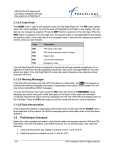
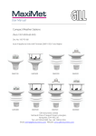
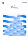
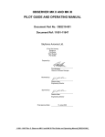
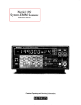
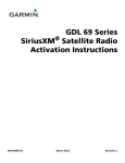
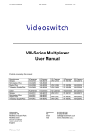
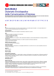
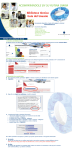
FDL-978-XVR/RX ADS-B Transceiver/Receiver Installation Manual SECTION X TRANSCEIVER/RECEIVER MAINTENANCE INTERFACE DIAGRAMS Section 3.4 describes the various FDL-978-XVR/RX configuration and setup options via the Maintenance Port Interface (MPI). The diagrams below provide a pictorial representation of these available options for accessing the maintenance port of the FDL978-XVR/RX. Figure 19. Off-the-shelf RS-232 to USB Converter Figure 20. Serial-to-USB MPI Cable and USB-MPI 87343, Rev. E September 16, 2014 X-1 FDL-978-XVR/RX ADS-B Transceiver/Receiver Installation Manual Figure 21. Serial-to-WiFi MPI 87343, Rev. E September 16, 2014 X-2 FDL-978-XVR/RX ADS-B Transceiver/Receiver Installation Manual Figure 22. Serial-to-WiFi Aircraft Module 87343, Rev. E September 16, 2014 X-3 FDL-978-XVR/RX ADS-B Transceiver/Receiver Installation Manual 3.2 PRELIMINARY CHECKOUT Before the unit is installed and tested, verify that all cables are properly secured. With the FDL-978-XVR/RX and TC978 removed, turn on aircraft power and verify the following: 1. Verify that Aircraft DC bus voltage is present on pins 1 and 16 of P1. 2. Verify that ground is present on pins 17 and 31 of P1. 3. Verify that the two UAT antenna coax center conductors are not shorted to its shield or aircraft ground. When the above conditions are verified, turn off the master power. Properly attach the external connectors to the FDL-978-XVR/RX and TC978. Mount the FDL-978-XVR/RX and TC978 in their respective mounting locations. Turn on master power and then turn on the TC978, if installed. During initialization the FDL-978-XVR/RX unit performs a comprehensive diagnostics test. A system component failure will be annunciated by a "Warning Indication" on the TC978, if installed, or the display. Warnings concerning the GPS status may not be displayed until 2.5 minutes after power on in order to give the GPS time to acquire satellites. Consult the Pilot Guide / User Manual for more information concerning WARNING messages. Detailed system status can be observed using the Maintenance Port Interface as described in Section 3.4. The FDL-978-XVR/RX aircraft installation must be verified to ensure compliant operation and configuration. The FFS FT-9000 Ramp Tester can be used for this purpose (see Section 1.5.2 for more information) and use of the FFS STC data requires the use of the FT-9000 for installation verification. 3.3 INSTALLATION SETUP AND CONFIGURATION System installation is configured using either: The MPI on serial port 3 or port 5 or, The TC978 Controller, if installed, in a special configuration mode. Sections 3.3 through 3.5 describe the system installation configuration details necessary for configuring the FDL-978-XVR/RX installation. Installers should review the information in these sections to ensure proper system configuration. It is important to carefully review Section 3.3.2 to ensure proper system configuration of the serial and ARINC ports, regardless of using the MPI or TC978 for configuration. For reference, the configuration sections are organized as follows: 3.3 Installation Setup and Configuration – General Configuration Details o 3.3.1 Configuration Item Summary – List of all Configuration Items o 3.3.2 Serial and ARINC Port Configuration Details – General Port Details 3.4 Configuration and Setup Using MPI 3.5 Configuration and Setup Using TC978 87343, Rev. E September 16, 2014 III-4 FDL-978-XVR/RX ADS-B Transceiver/Receiver Installation Manual 3.3.1 Configuration Item Summary Use the configuration setting lists below to document the system installation. SERIAL & ARINC PORT CONFIGURATION SETTINGS CONFIGURATION ITEM Serial Port 1 Configuration: Serial Port 2 Configuration: Serial Port 3 Configuration (1): Serial Port 4 Configuration: Serial Port 5 Configuration (2): Serial Port 6 Configuration: ARINC IN 1 Configuration: ARINC IN 2 Configuration: ARINC OUT 1 Configuration: (1) DEFAULT IN Function Baud IN FUNCTION OUT Function Baud IN Function OUT Function Baud IN Function Baud IN Function OUT Function Baud IN Function OUT Function Baud Function Speed Function Speed Function Speed SETTING GPS-Internal 19200 UNUSED UNUSED 9600 TMAP TMAP 38400 UNUSED 9600 MAINT MAINT 115200 MAINT MAINT 115200 UNUSED Low UNUSED Low UNUSED Low Serial Port 3 is not configurable on the TC978. Serial Port 5 is not available on the 87098-00 and 87098-10 Transceivers. (2) 87343, Rev. E September 16, 2014 III-5 FDL-978-XVR/RX ADS-B Transceiver/Receiver Installation Manual ADS-B TRANSMIT CONFIGURATION SETTINGS CONFIGURATION ITEM DEFAULT ICAO Address (Mode S) VFR Call Sign (Flight ID) GPS SDA Level GPS NACv Mode Receiver Configuration: 0 UAT Receiver Installed ES1090 Receiver Installed Emitter (Aircraft) Category Squat Mode Groundspeed Threshold Vehicle Size: UAT Antenna: GPS Antenna Offset: Mode A Receive Disable Squawk Transmit VFR Squawk Code (4) Length Width Diversity DC Ground Check Longitudinal Lateral (3) SETTING UNKNOWN UNKNOWN no978 no1090 UNKNOWN none 0 knots 0 0 Top Only No DC Gnd Chk No Data No Data disable off 1200 Disable Squawk Transmit is not configurable on the TC978. (3) (4) VFR Squawk Code is only set on the TC978. DISPLAY OUTPUT CONFIGURATION SETTINGS CONFIGURATION ITEM DEFAULT Max Targets Output Chelton CSA Enable (4) Traffic Velocity Validation max disable enable (4) (5) SETTING Chelton CSA Enable is not configurable on the TC978. Traffic Velocity Validation is not configurable on the TC978. (5) Refer to Section 3.4.2.13.3 for detailed information on determining the proper display output settings in this table. 87343, Rev. E September 16, 2014 III-6 FDL-978-XVR/RX ADS-B Transceiver/Receiver Installation Manual 3.3.2 Serial and ARINC Port Configuration Details The FDL-978-XVR Transceiver and FDL-978-RX Receiver installations require data interfaces to other equipment for complete aircraft installation. The necessary data interfaces are Control Input (Transceiver Only), GPS Input, Altitude Input, TCAS Input, and Display Output. The FDL-978-XVR/RX Serial and ARINC ports must be configured to enable these data interfaces and are described in the table below: Data Interfaces for FDL-978-XVR/RX Installation INTERFACE DESCRIPTION Control Input Control inputs such as Flight Plan ID (Squawk Code), call sign, and mode control (IDENT, Altitude Inhibit, transmit Standby) are needed by the FDL-978-XVR. The TC978 provides control or the FDL-978-XVR can be configured for other control formats. If a control format is configured and functional with the TC978 installed, the TC978 displays control status but will not accept control inputs. Serial port 2 is typically used for control input. Control Input is NOT required for receive only systems. GPS Input The FDL-978-XVR/RX requires position, velocity, time, and integrity data from a GPS sensor. The internal GPS or an external GPS must be configured to provide this data. Serial port 1 is typically used for GPS Input. Altitude Input The FDL-978-XVR/RX requires external pressure altitude data input from an altitude/air data sensor (ADS). Altitude rate and airspeed will be used if available in the configured protocol. Pressure altitude data output can also be configured to share with a transponder. Serial port 4 is typically used for Altitude Input. Heading Input The FDL-978-XVR/RX can optionally receive aircraft true heading data. True heading is sent in UAT transmit messages on the ground and is also used to more accurately correlate TCAS and ADS-B Traffic. Heading input is not required but desirable with TCAS installations. TCAS traffic MUST be input to the FDL-978-XVR/RX if the aircraft is TCAS equipped then so the TCAS traffic can be integrated with ADS-B traffic and one traffic picture can be presented to the Display output. The FDL-978-XVR accepts TCAS traffic input via ARINC input per the ARINC 735A/B Intruder Labels. TCAS Input Display Output ADS-B traffic and FIS-B data output can be sent to one or more displays simultaneously. A display control can also be configured to provide the Control Input. Three different Serial Ports can be configured to simultaneously provide display output: Display on Serial Port 3 Display on Serial Port 5 Display on either Port 2 or 6 ARINC OUT1 can also be configured to output ARINC 735 Intruder Traffic. 87343, Rev. E September 16, 2014 III-7 FDL-978-XVR/RX ADS-B Transceiver/Receiver Installation Manual The installer should configure Serial and ARINC ports to specific data functions which provide the necessary data interfaces. All data interface types (except Display Output) from the table above can be configured to one and only one Serial or ARINC port. If multiple Serial/ARINC ports are set to the same data interface type then only one port is actually configured and other settings of the same data interface type are ignored. The data interface order of precedence is as follows: 1. ARINC 429 ports take precedence over UART Serial ports 2. Lowest port channel number takes precedence over higher channel number For example, if the FDL-978-XVR/RX has an internal GPS and serial in 1 is set to ‘GPSInternal’ and ARINC in 1 is set to ‘GPS-743’ then the FDL-978-XVR/RX will not receive GPS data from the internal GPS. Set only one Control Input, only one Altitude Input, and only one GPS Input. Inadvertently setting more than one of the same input type may result in the correct input data not being received. Only ONE function can typically be set to either the input or output of each bi-directional Serial Port (2, 3, 5, or 6). If the serial port input is set to a function then the output should be set to ‘UNUSED’ and vice versa. If a Serial port’s input and output are both set only one setting is configured and unexpected operation can occur. The exception is if a display output is set on a port output then the port input can be set to display control otherwise the input should be set to ‘UNUSED’. (See paragraph 3.3.2.1 and 3.3.2.2 for details). Control Input is not required for receive only systems. 87343, Rev. E September 16, 2014 III-8 FDL-978-XVR/RX ADS-B Transceiver/Receiver Installation Manual 3.3.2.1 Serial Port Input Configuration The following tables define the serial port input data formats and baud rate settings: Serial Port Input Configuration Settings (1) Setting UNUSED Interface - Description No connection to serial port (Not Used) Altitude Input ADS (Air Data Sensor) Altitude Input Alt-Encoder (Altitude Encoder) GPS Input Internal-GPS (Internal GPS) GPS Input GPS-FFS (GPS-FreeFlight) GPS Input GPS-ADSBPlus (GPS-GNS ADS-B) Control Input GSL-71 (3) (Control Panel) Control Input GTX-Remote (3) (GTX Remote) Control Input Disp-Cntrl (3) (TIS/FIS) Altitude, Airspeed, and Vertical Rate data input. Format for air data sensors using the protocol in Section 6.2. Altitude data. Format for air data sensors using the protocol in Section 6.1. GPS position, velocity, time, and integrity data input and output. Selects use of the internal GPS (models with GPS only). Baud rate must be set to 19200. Internal GPS is only valid for serial port 1. The internal GPS data is used by the XVR/RX and GPS data is automatically output at 19200 baud on serial output port 1 using the FFS/Chelton Protocol. The output is TSO-C145c Class Beta 1 certified and can be used as an ADS-B position source or navigation source. GPS position, velocity, time, and integrity data input. Format for the FFS 1201 or other sensors that support the FFS/Chelton Protocol. Typically configured on port 1. GPS position, velocity, time, and integrity data input. Format for the Garmin Series 400/500 ADSBPlus GPS Protocol. Typically configured on port 1. Squawk code, IDENT, call sign, mode (standby/alt inhibit), and altitude data input. Format for the GSL-71 controller or SL 70 transponder. (2) Squawk code, IDENT, call sign, and mode (standby/alt inhibit) input. Format for GTX 330/33/327/32 transponders. Squawk code, IDENT, call sign, and mode (standby/alt inhibit). Enables display control from an MX-20, GMX200, or other displays using the GDL/FDL protocol. The corresponding serial output port must be configured to TIS-FIS or MX-20 at the same baud rate to enable display control input. (3) (1) MPI setting names are listed first with TC978 configuration menu names in parenthesis (). (2) Altitude input configuration of the GSL-71 / SL 70 can affect the control output baud rate. Refer to respective installation manuals for these units. (3) 87343, Rev. E Control Input is not required for receive only systems. September 16, 2014 III-9 FDL-978-XVR/RX ADS-B Transceiver/Receiver Installation Manual (3) Setting an input port to Disp-Cntrl (TIS/FIS) must correspond to setting the same output port to a display output. I.E., if serial port 6 output is set to Traffic-Alert (TIS/FIS) then serial port 6 input can be set to either a) Disp-Cntrl (TIS/FIS) to enable display control or b) UNUSED (Not Used) to disable display control. ONLY one display port should be set to Disp-Ctrl. Serial Port Input Baud Rate Settings Setting 4800, 9600, 19200, 38400, 57600, 115200 230400, 460800 Description These baud rates are typical for RS-232 or RS-422 equipment but the correct rate must be selected to match the interfacing equipment’s configured or default baud rate. These high baud rates are not normally recommended for RS-232 serial ports. 3.3.2.2 Serial Port Output Configuration The following tables define the serial port output data formats and baud rate: Serial Port Output Configuration Settings (1) Setting UNUSED Interface - Description No connection to serial port (Not Used) (Encoded Altitude) Altitude Output Xpndr-Monitor Control Input Alt-Encoder (XPDR Monitor) Display Output Traffic-Alert (TIS/FIS) Display Output Pass-Thru (ADS-B Pass Thru) Display Output MX-20 (MX-20) Altitude data. Format for sending altitude to a transponder or display using the protocol in Section 6.1. Sends requests for squawk code and IDENT input data. (Xpndr-Monitor Protocol) This selection requires both serial input and output connections. (2) Ownship data, traffic reports, and FIS-B data. Format for the Aspen, GMX-200, Chelton displays, or other displays using the GDL/FDL protocol. The corresponding serial port input can be configured to Disp-Cntrl to enable display control input. (3) Ownship data, ADS-B traffic data, and FIS-B data. Format for sending unprocessed, uncorrelated, and un-prioritized raw ADS-B messages. Traffic must be processed in another device to meet TSO-C195a ASSAP installation requirements. (3) Ownship data, traffic reports, and FIS-B data. Format for the MX-20. The corresponding serial input port can be configured to Disp Cntrl at the same baud rate to enable display control input. (3) (4) (1) Maintenance port setting names listed first with TC978 configuration menu setting names in parenthesis (). 87343, Rev. E September 16, 2014 III-10 FDL-978-XVR/RX ADS-B Transceiver/Receiver Installation Manual (2) Xpndr-Monitor selection requires a serial input and output port for operation. If, I.E., port 2 output is set to Xpndr-Monitor then serial port 2 input is automatically used for Xpndr-Monitor input and serial port 2 input should be set to ‘UNUSED’. (3) Setting Disp-Cntrl for an input port must correspond to setting a display output on the same output port. I.E., if serial port 6 output is set to MX-20 or Traffic-Alert then serial port 6 input can be set to Disp-Cntrl to enable control. (4) For proper traffic and status presentation on legacy displays, review display settings in paragraphs 3.4.2.13.3.2 and 3.4.2.13.3.3 and set accordingly. Serial Port Output Baud Rate Settings Setting 4800, 9600, 19200, 38400, 57600, 115200 230400, 460800 Description These baud rates are typical for RS-232 or RS-422 equipment but the correct rate must be selected to match the interfacing equipment’s configured or default baud rate. These high baud rates are not normally recommended for RS232 serial ports. 3.3.2.3 ARINC 429 Port Input Configuration The ARINC 429 input data formats and speed configuration settings are described in the following tables: ARINC 429 Port Input Configuration Settings (1) Setting UNUSED Interface - Description No connection to ARINC 429 input port (Not Used) ADC Altitude Input (Air Data Computer) ADC&AHRS (ADC+AHRS) AHRS (AHRS) Transpndr-Cntrl (Txpdr Control) GPS-743 (GPS) 87343, Rev. E Altitude & Heading Input Heading Input Heading Input GPS Input Altitude, Airspeed, Vertical Rate data input. Format for air data sensors and computers that output the Air Data Computer Labels listed in the table below. Altitude, Airspeed, Vertical Rate, & True Heading data input. Format for devices that output the Labels listed in the ADC&AHRS table below. True Heading data input. Format for devices that output the True Heading Label 314 Squawk code, IDENT, and call sign. Format for transponders or controllers that output the ARINC Transponder Control Data Labels listed in the table below. GPS position, velocity, time, and integrity data input. Format for the FFS 1203 and 1203C or other sensors that output the ARINC 743A labels (listed in GPS-743 Labels Table below) and ALSO outputs a Time Mark that is UTC second synchronized. September 16, 2014 III-11 FDL-978-XVR/RX ADS-B Transceiver/Receiver Installation Manual Setting (1) Traffic Interface TCAS Input (Traffic) Description TCAS Intruder Traffic data input. Format for TCAS that output the Labels listed in the Traffic Input table below. (1) Maintenance port setting names listed first with TC978 configuration menu setting names in parenthesis (). ARINC Port Input Speed Configuration Settings Setting low high Description Low speed ARINC 429 – 12.5 kBaud High speed ARINC 429 – 100 kBaud The ARINC 429 Input channels can be configured as the following: GPS-743 Input ARINC Labels LABEL DESCRIPTION 110 120 111 121 370 166 174 112 103 165 260 150 130 133 247 136 273 Latitude Coarse Latitude Fine Longitude Coarse Longitude Fine Altitude (HAE) North/South Velocity East/West Velocity Groundspeed True Track Angle Vertical Speed Date UTC Horizontal Integrity Limit (HIL) Vertical integrity Limit (VIL) Horizontal Figure of Merit (HFOM) Vertical Figure of Merit (VFOM) Sensor Status Transpnder-Cntrl Input ARINC Labels LABEL 016 031 233 234 235 236 DESCRIPTION TCAS/ATC Control (squawk code and IDENT only) ATCRBS Control (squawk code and IDENT only) Flight ID Characters 1&2 Flight ID Characters 3&4 Flight ID Characters 5&6 Flight ID Characters 7&8 Label 016 or 031 must be present as a minimum Labels 016 or 031 control only Squawk Code and IDENT Labels 233 – 236, if present, control Call Sign 87343, Rev. E September 16, 2014 III-12 FDL-978-XVR/RX ADS-B Transceiver/Receiver Installation Manual ADC Format Input ARINC Labels LABEL 203 210 212 DESCRIPTION Pressure Altitude Airspeed Altitude Rate AHRS Format Input ARINC Labels LABEL 314 DESCRIPTION True Heading ADC & AHRS Format Input ARINC Labels LABEL 203 210 212 314 DESCRIPTION Pressure Altitude Airspeed Altitude Rate True Heading Traffic Format Input ARINC Labels LABEL 274 350 314 357 130 131 132 DESCRIPTION TCAS Output – Receiver health in System Status Fault Summary – TA only mode set in RI field True Heading RTS and ETX words for Intruder File Intruder Range Intruder Altitude Intruder Bearing 3.3.2.4 ARINC 429 Port Output Configuration The ARINC 429 output data formats and speed configuration settings are described in the following tables: ARINC 429 Port Output Configuration Settings (1) Setting UNUSED Interface - Description No connection to ARINC 429 output port (Not Used) Display Output Traffic (Traffic) Ownship data and traffic intruder data format for displays that receive the ARINC 735 Traffic Labels listed in the table below (1) Maintenance port setting names listed first with TC978 configuration menu setting names in parenthesis (). ARINC 429 Port Output Speed Configuration Settings Setting low high 87343, Rev. E Description Low speed ARINC 429 – 12.5 kBaud High speed ARINC 429 – 100 kBaud September 16, 2014 III-13 FDL-978-XVR/RX ADS-B Transceiver/Receiver Installation Manual The ARINC 429 Output channel can be configured as the following: Traffic Format Output ARINC Labels LABEL 274 350 357 130 131 132 3.4 DESCRIPTION TCAS Output – Receiver health in System Status Fault Summary – TA only mode set in RI field RTS and ETX words for Intruder File Intruder Range Intruder Altitude Intruder Bearing CONFIGURATION AND SETUP USING MPI This section describes FDL-978-XVR/RX configuration and setup via the MPI on Serial Port 3 or 5. The MPI connections detailed in paragraph 2.6.11 can be connected to a PC or Tablet via one of following four devices: Off-the-shelf RS-232 to USB converter Serial-to-WiFi MPI Module, WiFi-MPI (P/N 87710-00) from FFS Serial-to-WiFi Aircraft Module (P/N 86943-00) from FFS Serial-to-USB MPI Cable, USB-MPI (P/N 86971-00-2) from FFS Please refer to Section X for descriptions on connecting the above devices from the FDL-978-XVR/RX to a PC or Tablet. The battery powered Serial-to-Wifi MPI Module, WiFi-MPI (P/N 87710-00) or the Serialto-WiFi Aircraft Module (P/N 86943-00) can use the available MPI Tablet Application. The MPI Tablet Application provides a complete Graphical User Interface (GUI) for configuring, troubleshooting, and updating the system. The MPI Tablet Application, called “ADS-B MPI”, includes user documentation and can be obtain from the Google Playstore or through FFS. An example screenshot is shown below: 87343, Rev. E September 16, 2014 III-14 FDL-978-XVR/RX ADS-B Transceiver/Receiver Installation Manual The following 3.4 sub-sections describe interfacing directly to the MPI using a terminal interface program on a PC, like “Tera Term”, to enter MPI commands. Any of the four interface devices mentioned above can be used to interface to the PC. 3.4.1 Terminal Program Interface “Tera Term” should be installed on the PC and a MPI connection made via serial port or WiFi depending on the interface device used. The following two sub-paragraphs detail the serial port settings and WiFi settings. 3.4.1.1 MPI Serial Connection Settings The typical “Tera Term” serial port settings for a serial connection are: BAUD Rate 115200 Parity – None Data bits - 8 Stop - 1 Flow Control – None The default Port 3 settings are be Baud Rate: 38400, Parity: odd, Data bits: 8, Stop: 1, & Flow Control: none. The terminal setup should be set to: Local Echo – checked 3.4.1.2 MPI WiFi Connection Settings A WiFi connection to the WiFi Module SSID must first be made on the PC. The typical “Tera Term” TCP settings for the WiFi connection are: Host: 192.168.10.1 TCP Port#: 44000 Service: Other - 8 Protocol: UNSPEC The terminal setup should be set to: Local Echo – checked 3.4.1.3 Initial MPI Connection Once connected to the MPI with a serial or WiFi connection, type the <Enter> key three times to remove the maintenance lockout. The following prompt should be displayed: RANGR-XVR> (Transceiver) or RANGR-RX> (Receiver) 87343, Rev. E September 16, 2014 III-15 FDL-978-XVR/RX ADS-B Transceiver/Receiver Installation Manual 3.4.2 Maintenance Commands The available commands are summarized in the table below: Command ads bit comm control cnfg gps help or ? info Reset rx status set <item> <value> stop cnfg defaults cnfgstatus Description Display data from the altitude/air data input Display built-in test status Display communication ports’ status - continuous Display control squawk and mode status Display configuration data Display data from the GPS input Display command help Display info – S/N, operation hours, versions, etc. Reset and restart the unit Display receiver status info – continuous Set a configuration item’s value Stop continuous data outputs Reset configuration to defaults Display configuration status 3.4.2.1 “help or ?” Command This command displays a list of available commands as shown below: 87343, Rev. E September 16, 2014 III-16 FDL-978-XVR/RX ADS-B Transceiver/Receiver Installation Manual 3.4.2.2 “ads” Command This command displays the data from the Altitude/Air Data input interface. 3.4.2.3 “bit” Command This command displays built-in-test information about the FDL-978-XVR\RX health. Example output is displayed below: 3.4.2.4 “comm” Command This command continually displays serial port communication status information: enabled/disabled status and receive and transmit byte count and errors. The data is updated once per second. Example output is displayed below: Type the “stop” command to stop updating and return to the prompt. 87343, Rev. E September 16, 2014 III-17 FDL-978-XVR/RX ADS-B Transceiver/Receiver Installation Manual 3.4.2.5 “control” Command This command displays the control, squawk and mode status including the squawk code, IDENT status, altitude control status, call sign, transmit control status and vertical status. 3.4.2.6 “gps” Command This command displays data which is being received from the GPS input. 3.4.2.7 “info” Command This command displays information such as Serial Number, operation time and hardware and software version information about the FDL-978-XVR\RX. Example output is displayed below: 87343, Rev. E September 16, 2014 III-18 FDL-978-XVR/RX ADS-B Transceiver/Receiver Installation Manual 3.4.2.8 “Reset” Command This command causes the FDL-978-XVR\RX to reboot and restart. 87343, Rev. E September 16, 2014 III-19 FDL-978-XVR/RX ADS-B Transceiver/Receiver Installation Manual 3.4.2.9 “rx status” Command This command displays detailed status and other information about the ADS-B data being received by the FDL-978-XVR\RX. Example output is displayed below: The output displayed contains an initial section with general count information (current UTC second, receiver loop count, and receiver word count). These counts will increment at varying rates when the receiver is operating correctly. The next rx status output section displays general message count information for ground Uplink, basic, and long message types. The displayed counts include total messages received (Total), messages received in the last second (LstSec) and messages with various counts of corrected Reed-Solomon errors (RSErr:x). The third rx status section displays detailed traffic information. This information includes total number of traffic targets being tracked and then detailed information about the ownship data being received and the 10 closest traffic targets. The detailed traffic information includes address (Addr), address type (Typ), call sign, Latitude, Longitude, altitude in feet (Alt), speed in knots (Spd), air ground status (AG), message count (msgs), signal strength indication in dbm (SSI), and traffic time out in seconds (TO). Traffic targets will time out being tracked if no ADS-B message is received from the target for more than twenty five seconds. 87343, Rev. E September 16, 2014 III-20 FDL-978-XVR/RX ADS-B Transceiver/Receiver Installation Manual The fourth rx status section displays detailed ground station information. This information includes total number of ground stations being received and detailed information about the 10 closest ground stations. The detailed ground station information includes Latitude, Longitude, Site ID, time slot of last transmission, message count (Msgs), signal strength indication in dbm (SSI), and ground station time out in seconds (TO). Ground stations will time out being tracked if no ADS-B uplink message is received from the ground station for more than forty seconds. Type the “stop” command to stop updating rx status and return to the prompt. 3.4.2.10 “cnfg” Command This command displays configurable information such as the serial port settings (protocol and baud rate), the ICAO address, and the VFR Call Sign. Example output is displayed below: 3.4.2.11 “cnfgstatus” Command This command displays a summary of the serial/ARINC port configuration status for various interfaces (GPS, Altitude, Control, Display, etc.). Details are shown on what port is configured and data reception status for each of the functional interfaces. 87343, Rev. E September 16, 2014 III-21 FDL-978-XVR/RX ADS-B Transceiver/Receiver Installation Manual 3.4.2.12 “cnfg defaults” Command This command resets all configuration values to default factory settings. 3.4.2.13 “set” Command This command is used to modify configuration settings such as ICAO address, call sign, and serial port function. Help on this command is displayed by entering “set ?”. Example “set ?” output is displayed below. 3.4.2.13.1 Serial and ARINC Port Settings This section describes the configuration settings for serial and ARINC port functionality. 87343, Rev. E September 16, 2014 III-22 FDL-978-XVR/RX ADS-B Transceiver/Receiver Installation Manual 3.4.2.13.1.1 “set serial in” Command This command sets the Serial Port Input configuration options. Help on this command is displayed by entering “set serial in ?”. Example “set serial in ?” output is displayed below: Refer to Section 3.3.2.1 for information on selecting serial input settings. 87098-00 and 87098-10 Transceivers do not allow Serial Port 5 settings. 87343, Rev. E September 16, 2014 III-23 FDL-978-XVR/RX ADS-B Transceiver/Receiver Installation Manual 3.4.2.13.1.2 “set serial out” Command This command sets the Serial Port Output configuration options. Help on this command is displayed by entering “set serial out ?”. Example “set serial out ?” output is displayed below: Refer to Section 3.3.2.2 for information on selecting serial output settings. Serial Port 4 is input ONLY and doesn’t accept output settings. 87098-00 and 87098-10 Transceivers do not allow Serial Port 5 settings 3.4.2.13.1.3 “set arinc in” Command This command sets the ARINC 429 input configuration for ports 1 and 2. Refer to Section 3.3.2.3 for information on selecting ARINC input settings. 87343, Rev. E September 16, 2014 III-24 FDL-978-XVR/RX ADS-B Transceiver/Receiver Installation Manual 3.4.2.13.1.4 “set arinc out” Command This command sets the ARINC 429 output configuration for port 1. Note that there is only one ARINC 429 output port. Refer to Section 3.3.2.4 for information on selecting ARINC output settings. 3.4.2.13.2 ADS-B Transmit Settings This section describes configuration settings mainly for transmitting ADS-B messages. Some of these settings are relevant for receiver only units as well. 3.4.2.13.2.1 “set addr” Command This command is used to set the ICAO address of the aircraft. For example, to set the ICAO address to ABCD12, enter “set addr ABCD12”. The ICAO address must be entered as a hex value. The FDL-978-XVR/RX requires the ICAO to be set to the aircraft’s registered ICAO address. This should be set for receivers and transceivers. 3.4.2.13.2.2 “set call sign” Command This command sets the default call sign of the aircraft and is typically the aircraft tail number. For example, to set the call sign to ABCD1234, enter “set call sign ABCD1234”. The default call sign is transmitted by a Transceiver if a call sign setting is not received from a configured transmit controller (transponder, TC978, etc.). In a receiver the default call sign is for informational purposes only. 3.4.2.13.2.3 “set gps” Command This command sets the system design assurance level for the GPS input. Internal GPS should be set to Level C. For external GPS units refer to the GPS manufacturer’s data 87343, Rev. E September 16, 2014 III-25 FDL-978-XVR/RX ADS-B Transceiver/Receiver Installation Manual for setting system design assurance level. This should be set for both receivers and transceivers. 3.4.2.13.2.4 “set nacv” Command This command sets the Navigation Accuracy Category for velocity (NACv) for the GPS input. Internal GPS should be set to 3 (auto). For external GPS units refer to the GPS manufacturer’s data for setting NACv. This should be set for both receivers and transceivers. 3.4.2.13.2.5 “set rx” Command This command sets the receiver installed options to be transmitted by a Transceiver. Transceivers should be set to 978 and no1090. It is not necessary to set this for a receiver only. 3.4.2.13.2.6 “set emit cat” Command This command sets the emitter category of the aircraft and must be set to something other than the default of 0 (no aircraft type). This should be set for transceivers and receivers. 87343, Rev. E September 16, 2014 III-26 FDL-978-XVR/RX ADS-B Transceiver/Receiver Installation Manual 3.4.2.13.2.7 “set squat” Command This command sets the active state (low or high) for the squat switch of the aircraft or to indicate there is no active squat switch. The squat switch (or other air/ground determination discrete) is an automatic means to indicate when the aircraft is on the ground or in the air. This should be set for transceivers and receivers. 87343, Rev. E September 16, 2014 III-27 FDL-978-XVR/RX ADS-B Transceiver/Receiver Installation Manual 3.4.2.13.2.8 “set threshold” Command This command sets the groundspeed threshold which is used to determine when the aircraft is on the ground if an automatic means (squat switch) is not configured for the Small Aircraft (2) Emitter Category only. A groundspeed of less than the threshold indicates the aircraft is on the ground. Setting this parameter is only required for transceivers but not receiver only models. 3.4.2.13.2.9 “set acsize” Command This command sets the aircraft size that is used to set the aircraft size code transmitted by the Transceiver. Setting this parameter is only required for transceivers but not receiver only models. 3.4.2.13.2.10 “set uatant” Command This command sets the UAT antenna configuration. This should be set for transceivers and receivers. 3.4.2.13.2.11 “set gpsant” Command This command sets the GPS antenna configuration. This should be set for transceivers but is not necessary for receivers. 87343, Rev. E September 16, 2014 III-28 FDL-978-XVR/RX ADS-B Transceiver/Receiver Installation Manual 3.4.2.13.2.12 “set modeArx” Command This command enables/disables Mode A code reception from the on-aircraft Mode A/C transponder. When enabled Flight Plan ID (squawk code) and IDENT are received from the on aircraft’s Mode A/C transponder via its RF transmissions. The default setting is “disable”. This is only used with transceivers and should not be set in receiver only units. 3.4.2.13.2.13 “set disableSquawkTx” Command This command disables the squawk code transmissions over the UAT datalink when set to “on”. This setting should not be set to “on” and left to the default “off” setting. This is only used with transceivers and should not be set in receiver only units. 3.4.2.13.3 Display Output Settings This section describes configuration settings for controlling traffic display output typically for legacy displays. 87343, Rev. E September 16, 2014 III-29 FDL-978-XVR/RX ADS-B Transceiver/Receiver Installation Manual 3.4.2.13.3.1 “set max trgs” Command This command sets the maximum number of targets to be sent on any configured serial or ARINC 429 port configured for traffic display output. This is typically used to limit the number of traffic targets for displays that can process a large number of traffic targets. 3.4.2.13.3.2 “set cheltonCSA” Command This command enables/disables the (Conflict Situational Awareness) CSA bit in the Heartbeat message of the “Traffic-Alert” protocol. This parameter defaults to “disable” and should ONLY be set to “enable” when interfacing to a Chelton FlightLogic Display. The legacy Chelton display is not TSOC-195a compliant and requires this Heartbeat message bit to be set or it will generate an ADS-B failure. The FDL-978-XVR does not implement a Conflict Situation Awareness (CSA) algorithm since DO-217A and TSOC195a do not currently specify any CSA applications. For all other displays leave this parameter at the default setting of “disable”. 3.4.2.13.3.3 “set trafVelVal” Command This command enables/disables the DO-317A/TSOC-195A Traffic Velocity Validation\Invalidation of legacy ADS-B Transmitters that transmit NACv values of 0. This parameter defaults to “enable” and should ONLY be set to “disable” when interfacing to legacy displays that are 1) not TSOC-195a compliant and 2) don’t adequately display non-directional traffic symbols. Several non-TSOC-195a displays adequately display non-directional traffic and do not require velocity validation /invalidation to be disabled. The legacy MX-20 Display does not support non-directional traffic symbols and instead displays a directional traffic symbol pointing at approximately 120 degrees from North. The FDL-978-XVR/RX attempts to validate NACv=0 velocities per DO-317A/TSOC-195a but some traffic states (low-speed ground) will still cause the NACv=0 track velocities to be invalidated and sent to the display as non-directional traffic. Setting this parameter to “disable” turns off all DO-317A/TSOC-195a velocity validation/invalidation and passes the track’s velocity data to the display as directional traffic. This parameter should only be set to “disable” for legacy non-TSO-C195a displays without non-directional traffic symbols when occasional display of non-directional traffic is deemed to be unacceptable or misleading. Otherwise leave this parameter at the default setting of “enable”. 87343, Rev. E September 16, 2014 III-30 FDL-978-XVR/RX ADS-B Transceiver/Receiver Installation Manual 87343, Rev. E September 16, 2014 III-31