1
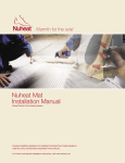
Installation Manual Cable Floor Heating System Copyright © 2012 Warm Feet™ P.O. Box 333 Saint-Bruno QC J3V 5G8 Canada TEL: 1-866-994-4664 FAX: 1 450 482 1920 www.warmfeet.ca TABLE OF CONTENTS Important safeguards and warnings 1 1 General information 2 1.1 Use of the manual 2 1.2 Safety guidelines 2 1.3 Remember to measure resistance 2 1.4 25-year limited warranty 3 2 Warm Feet cable system 4 2.1 Cable specifications 4 2.2 Thermostat specifications 4 2.3 Typical installations and applications 5 3 Floor heating design and product selection 7 3.1 Design the installation 7 3.2 Confirm your product selection 9 4 Installation 10 5 Commissioning 15 5.1 Insulation resistance test 15 5.2 Heating cable resistance test 15 5.3 Sensor resistance test 16 6 Troubleshooting 16 EXTENDED WARRANTY 17 II Important Safeguards and Warnings WARNING: Shock and fire hazard If the cable system is damaged or not installed properly, fire or shock could occur resulting in serious personal injury or damage to property. You must carefully follow the warnings and instructions contained in this manual. The Warm Feet™ thermostat must be used. It is important that this equipment is installed only by qualified electricians who are familiar with the proper sizing, installation, construction and operation of floor warming systems and the hazards involved. The installation must comply with all national and local electrical codes. If you are unfamiliar with these requirements, contact an electrician. The heating cable is designed for under floor heating purposes only. Be sure that the floor is not penetrated by nails, screws, or similar devices that can cause damage on first installation or during subsequent floor repairs in the future. If the cable system is damaged, it must be replaced. Do not attempt to splice or repair any part of the system. Important information First-time installers should call the Warm Feet™ toll free number at 1-866-994-4664. Read the installation manual before installing the product. Install this electrical product only according to manufacturer’s guidelines. The installation of the product shall be in accordance the Canadian Electrical Code Part 1 or the National Electrical Code (US) where applicable. Perform the mandatory tests described in this guide and record results. This product must be installed only by a qualified installer. Heating cable must be at least 15 cm (6 in) away from any heat source. Install Warm Feet™ above 5 degrees Celsius or 40 degrees Fahrenheit. The cable cannot be cut or overlapped Do not make any changes or alterations to the cable. Use only approved cable guides sold by Warm Feet™ to secure the cable to the sub-floor. Any substitution will void the warranty. A class A GFCI or GFCI circuit breaker must be installed. Install cables a minimum of 3 inches apart. Do not install product if the safety seal on the box has been broken. Do not install on or in walls. The cable set must not extend beyond the room or area in which it originates. All of the heating cable including the connection joint must be covered with self-leveling cement or thinset cement. See cement manufacturers’ recommendations for product installation over heating cable. 1 1 General Information 1.1 Use of the Manual This manual describes the Warm Feet™ floor heating system — how to design the room, select the product, and install the system. It is important to thoroughly review this manual and the Warm Feet™ Thermostat Installation and Operation Manual prior to installation. For additional information regarding any aspect of the cable system, contact: Warm Feet™ P.O. Box 333 Saint-Bruno Québec J3V 5G8 Canada Tel: 450 482 1919 Toll free: 1 1-866-994-4664 Fax: 1 450 482 1920 www.warmfeet.ca Email: [email protected] 1.2 Safety Guidelines The safety and reliability of any floor heating system depends on proper design, installation and testing. Incorrect installation or mishandling of the product can cause damage to the heating cable, system components and property, and can create a risk of fire or shock. The guidelines and instructions contained in this guide are important. Follow them carefully to minimize these risks and to ensure that the cable system performs reliably. Pay special attention to the following: Instructions marked IMPORTANT Safety warnings identified as WARNING 1.3 Remember to Measure Resistance The resistance should be measured between the two conductors: white and black or red and black. Compare this resistance reading to the resistance specified on the product tag. The value should be within ±10%. If you get a different reading, contact Warm Feet™ at 1-866-994-4664. Also, measure the resistance between the white, black or red and shielding/ground wire. Both should read infinity. If you get a different reading, contact Warm Feet © at 1-866-994-4664. Please refer to Section 5 Commissioning for instructions on how to measure the resistance. 2 IMPORTANT: Measure the resistance four times during the installation Remember to always measure, verify and record the actual resistance throughout the installation process (out of the box, after installation, after thinset cement or self-leveler application, and after installation of final floor covering). 1.4 25-year Limited Warranty For a period of 25 years, to the original owner and/or purchaser, Warm Feet™ warrants that the heating cable will be free from defects in material, design and workmanship. The extended warranty is only valid if the warranty certificate has been properly completed and mailed, and the installation is in accordance with the installation instructions. 3 2 Warm Feet™ Cable System 2.1 Cable Specifications Cable construction: twin conductor Rated voltage: 120V, 240V Output: 3W/ft (9.84W/m) ±10% Heating element size: 40 ft to 800 ft (12.2 to 243.8 m) Bending radius: 1 in (25.4 mm) Cable diameter: 1/8 to 1/6 in (3.2 to 4.2 mm) Conductor insulation: fluoropolymer Outer insulation: fluoropolymer or TPE or nylon Max. ambient temp.: 85°F (30°C) Min. installation temp.: 40°F (5°C) Cold lead: 2-wire 16 AWG plus ground braid; 10 ft (3 m) length 2.2 Thermostat specifications Functions: On/off control, digital display, 7-day programmable Supply voltage: 120/240 V ±15%, 50/60 Hz Maximum switching current: 15 amps with GFIC Temperature control range: 40 to 104°F (5 to 40°C) Ambient range: 32 to 104°F (0 to 40°C) Floor temperature sensor: 2-wire, 10-ft lead wire 4 2.3 Typical Installations and Applications DIRECTLY ON PLYWOOD: Figure 1 DIRECTLY ON CONCRETE: Figure 2 ALTERNATIVE METHOD: Self-leveling cement is also recommended to cover the cables. Installation can be done under some of and with the approval of their manufacturers: engineered wood, laminate wood and some flexible materials (vinyl, linoleum and carpets). WARNING Consult the manufacturer for information on special installation requirements for wood, laminate, carpet, vinyl or linoleum flooring. 5 IMPORTANT Read the instructions carefully before installing the cable system. Remember to measure the resistance four times. Do not install the cable in walls or ceilings. The cable must be embedded in mortar, thinset, concrete or similar material. The minimum installation temperature is 40°F (5°C). The heating cable cannot be cut to length, crossed over itself, or installed too closely together. It is recommended to use copper wire only. Remember to check that the supply voltage matches the voltage of the cable. Remember to place the labels as written in these instructions. For indoor installation only. Metal structures or materials used for the support of or on which the cable is installed must be grounded in accordance with CSA Standard C22.1, Section 10 and the NEC. Please consult the factory for any other questions or advice. 6 3 Floor Heating Design and Product Selection 3.1 Design the Installation STEP 1: MEASURE THE HEATED AREA Determine the heated area of the floor where there are no permanent fixtures or furniture such as showers, toilets, vanities, or cabinets. Measure the heated area of the floor. For example, in Figure 3, the area of the bathroom is 96 ft 2. When you subtract the area of the vanity, shower and toilet, the total heated area is only 74 ft 2. STEP 2: DETERMINE THE POWER SUPPLY VOLTAGE The available supply voltages include 120V or 240V. STEP 3: PLAN THE DESIGN Determine the optimum floor heating cable layout with the help of our layout chart for your heated area to ensure adequate coverage. Select a spot for the thermostat in the wall above the heated area where it can be reached by the 10-ft cold lead on the cable and the 15-ft floor temperature sensor. Please refer to Figure 4. It is recommended to leave a minimum of 2 inches between the perimeter walls and the first heating cable. 7 IMPORTANT The predetermined cable spacing must be maintained to ensure proper floor heating. Do not change the cable heating spacing when you layout the cable or the floor may have cold spots. 8 3.2 Confirm Your Product Selection Confirm that your cable is no larger than the heated area. Following the example from Figure 3, if the heated area is 74 ft2, select the proper cable system. Table 1: 240V Product Selection Thickness Type Voltage Ohms Length 12 watts/sq ft 9 watts/sq ft (ft) 3 inches apart 4 inches apart Watts Amps (mm) CWF - 240V - 15 240V 360 180 0,5 3,480 60 17 to 22 Sq/Ft 23 to 29 Sq/Ft CWF - 240V - 20 240V 240 240 1 3,482 80 23 to 27 Sq/Ft 30 to 36 Sq/Ft CWF - 240V - 30 240V 180 360 1,5 3,482 120 33 to 38 Sq/Ft 44 to 50 Sq/Ft CWF - 240V - 40 240V 120 480 2 3,448 160 39 to 43 Sq/Ft 51 to 57 Sq/Ft CWF - 240V - 50 240V 100 600 2,5 3,502 200 49 to 54 Sq/Ft 65 to 71 Sq/Ft CWF - 240V - 60 240V 80 720 3 3,48 240 55 to 64 Sq/Ft 72 to 85 Sq/Ft CWF - 240V - 70 240V 70 840 3,5 3,604 280 65 to 75 Sq/Ft 86 to 99 Sq/Ft CWF - 240V - 80 240V 60 960 4 3,518 320 76 to 85 Sq/Ft 100 to 112 Sq/Ft CWF - 240V - 90 240V 54 1080 4,5 3,594 360 86 to 95 Sq/Ft 113 to 126 Sq/Ft CWF - 240V - 100 240V 48 1200 5 3,48 400 96 to 105 Sq/Ft 127 to 140 Sq/Ft CWF - 240V - 120 240V 40 1440 6 3,6 480 106 to 116 Sq/Ft 141 to 154 Sq/Ft CWF - 240V - 140 240V 35 1680 7 3,74 560 117 to 126 Sq/Ft 155 to 167 Sq/Ft CWF - 240V - 160 240V 30 1920 8 3,86 640 127 to 147 Sq/Ft 168 to 194 Sq/Ft CWF - 240V - 180 240V 27 2160 9 4 720 148 to 167 Sq/Ft 195 to 222 Sq/Ft CWF - 240V - 200 240V 24 1440 10 4,12 800 168 to 182 Sq/Ft 223 to 249 Sq/Ft CWF - 240V - 220 240V 22 2640 11 4,48 880 184 to 208 Sq/Ft 250 to 276 Sq/Ft CWF - 240V - 240 240V 20 2880 12 4,66 960 209 to 229 Sq/Ft 277 to 322 Sq/Ft Table 2: 120V Product Selection Type Thickness Length 12 watts/sq ft 9 watts/sq ft (mm) (ft) 3 inches apart. 4 inches apart. Voltage Ohms Watts Amps CWF – 120V - 15 120V 80 180 1,5 3,482 60 12 to 16 Sq/Ft 15 to 22 Sq/Ft CWF – 120V - 20 120V 60 240 2 3,448 80 17 to 22 Sq/Ft 23 to 29 Sq/Ft CWF – 120V - 25 120V 48 300 2,5 3,502 100 23 to 27 Sq/Ft 30 to 36 Sq/Ft CWF – 120V - 30 120V 40 360 3 3,482 120 28 to 32 Sq/Ft 37 to 43 Sq/Ft CWF – 120V - 35 120V 34 420 3,5 3,604 140 33 to 38 Sq/Ft 44 to 50 Sq/Ft CWF – 120V - 40 120V 30 480 4 3,518 160 39 to 43 Sq/Ft 51 to 57 Sq/Ft CWF – 120V - 45 120V 26 540 4,5 3,594 180 44 to 48 Sq/Ft 58 to 64 Sq/Ft CWF – 120V - 50 120V 24 600 5 3,48 200 49 to 54 Sq/Ft 65 to 71 Sq/Ft CWF – 120V - 60 120V 20 720 6 3,6 240 55 to 64 Sq/Ft 72 to 85 Sq/Ft CWF – 120V - 70 120V 17 840 7 3,74 280 65 to 75 Sq/Ft 86 to 99 Sq/Ft CWF – 120V - 80 120V 15 960 8 3,86 320 76 to 85 Sq/Ft 100 to 112 Sq/Ft CWF – 120V - 90 120V 13 1080 9 4 360 86 to 95 Sq/Ft 113 to 126 Sq/Ft CWF – 120V- 100 120V 12 1200 10 4,12 400 96 to 105 Sq/Ft 127 to 140 Sq/Ft CWF – 120V - 110 120V 11 1320 11 4,48 440 106 to 116 Sq/Ft 141 to 154 Sq/Ft CWF – 120V - 120 120V 10 1440 12 4,66 480 117 to 126 Sq/Ft 155 to 167 Sq/Ft 9 4 Installation IMPORTANT: Tools and materials required You will require the following items to install and test the floor heating system: Scissors Utility knife Wire strippers Tape measure Screwdriver Multimeter You will also need the appropriate tools and materials to install your particular floor. These will likely include products like self-leveling mortar, thinset mortar, backer board, tile, a notched trowel, and any other tools for your specific floor. FOLLOW THESE STEPS TO ENSURE A SUCCESSFUL CABLE INSTALLATION STEP 1: PLAN LAYOUT Make a sketch layout or a floor plan of the room. Include all permanent furnishings such as toilets, bathtubs, appliances, cabinetry, etc. Indicate the position of the thermostat and all dimensions required to determine the available floor area. IMPORTANT Warm Feet™ recommends that the installation is documented with photos to note the location of connections and the sensor. STEP 2: TRANSFER LAYOUT TO FLOOR Draw an outline of the layout on the floor including a foot print of all furnishings that are not yet installed. Unroll the first few feet of the heating cable. The starting point of the cable must be placed within 10 ft from the thermostat. Using your floor plan, determine your desired spacing of cable (standard 3 or 4 inch C/C) and strapping (recommended 5 ft to 6 ft apart). 10 IMPORTANT Minimum distance between the cables must be 3 in or greater. Mark the position of the connection point between the power lead and the black heating cable. This connection must be concealed in thinset or self-leveling cement. When using a floor-temperature-sensing thermostat, mark the sensor position in the middle of two heating cables, about 10 in (25 cm) away from the wall (within the heated area), as close as possible to the thermostat. STEP 3: INSTALL SENSOR If using a floor-temperature-sensing thermostat, install the sensor now, either in conduit tube, or directly to the subfloor. It is recommended that the sensor be installed in conduit tube to allow the sensor to be easily replaced in the unlikely event of failure. The sensor and/or tube needs to be installed between the thermostat wall box and the sensor position. The conduit tube must be partially countersunk into the subfloor. Cut a channel approximately 5/16 in deep × 5/16 in wide in the floor and wall up to the thermostat for the sensor conduit. The conduit has to go from the thermostat and minimum of 10 in away from the wall towards the middle of the floor. IMPORTANT The sensor conduit must be centered in the cable loop (between two blue heating wires). Use duct tape to close the end of the conduit so that thinset cannot penetrate the conduit. Use duct tape to hold the sensor conduit into the groove to prevent it from floating up when the mortar or thinset is poured. If the sensor is installed directly in the mortar bed, use duct tape to secure it to the subfloor. 11 STEP 4: PREPARE SUBFLOOR SURFACE Clean and vacuum the floor thoroughly and remove dust and debris from the floor that may damage the heating cable. Ensure that the subfloor is secure and stable. Carefully fill in all cracks to prevent any potential damage to the new tiles resulting from shifts in the subfloor. STEP 5: MEASURE THE RESISTANCE (THE FIRST TIME) Use a digital ohm meter to measure the resistance of the cable and compare it to the ohms specified on the sticker of the cable. Record the measured resistance on the warranty card. Documenting the resistance at each stage of installation is required for warranty purposes. Also, measure the resistance between the white, black and shielding/ground wire. Both should read infinity. Please refer to Section 5 Commissioning for instructions on how to measure the resistance. STEP 6: BEGIN LAYING THE CABLE Place the cable so that the connection point and the temperature sensor are in their intended positions and bring the power lead cable to the thermostat or connection box. Begin laying the heating cable according to the layout determined in Step 1. WARNING: DO NOT CUT OR SHORTEN THE HEATING CABLE Do not expose the cable to any mechanical stress. Avoid walking on the heating cable. Wear only shoes with soft soles. Use cable strapping to secure the cable to the subfloor. Attach the cable strapping with adhesive, nails, staples, or double-sided tape. Please refer to Step 8 for instructions on how to use the cable strapping. ENSURE THAT THE SENSOR CONDUIT HAS BEEN PROPERLY INSTALLED BEFORE PROCEEDING (refer to Step 3). It is highly recommended to take photographs of the installed cable before installing the flooring. 12 STEP 7: MEASURE THE RESISTANCE (THE SECOND TIME) Refer to Step 5. STEP 8: CABLE GUIDES INSTALLATION INSTRUCTIONS Space the cable guides at a maximum distance of 7 Ft. Secure the cable guides to the subfloor with adhesive, staples, nails, or double-sided tape. Standard cable spacing on the cable guides is 3 or 4 inch C/C. When a room is wider the 7 Ft. the parallel cable guides should be spaced at 3 inches. Figure 5 13 STEP 9: EMBED THE FLOOR HEATING CABLE IN MORTAR For tiling applications, proceed with the installation of the tiles by covering the heating cables with a layer of thinset cement as directed by the tile manufacturer. Ensure that the thinset mortar covers the entire heating cable as the tiles are installed. For engineered wood or laminate floor coverings, it is recommended to consult the flooring manufacturer for maximum temperature allowance (use a thermostat with a floor temperature limiter). Ensure that all moisture in the self-leveling cement has been fully eliminated in accordance with the drying times recommended by the cement manufacturer (consult the manufacturer for exact drying time). IMPORTANT The system must not be turned on until the thinset cement has fully dried. A minimum of two weeks is recommended. STEP 10: MEASURE THE RESISTANCE (THE THIRD TIME) Refer to Step 5. STEP 11: INSTALL THE TILE To install the tile, apply a layer of acrylic or latex modified thinset using the ridged side of your trowel. Tile and grout the floor being sure to follow industry best practices and in accordance to the tile manufacturer’s instructions and recommendations. STEP 12: CONNECT POWER SUPPLY AND THERMOSTAT Connection of the power supply and the thermostat must be done by a qualified electrician in accordance with the National Electrical Code (NEC) and the Canadian Electrical Code (CEC). The electrician should connect the floor sensor to the thermostat, take the final resistance reading and record it on the warranty card. Note: Mark the appropriate circuit breaker reference label indicating which branch supplies the circuits to the cables. STEP 13: MEASURE THE RESISTANCE (THE FOURTH TIME) Refer to Step 5. 14 STEP 14: RECORD INFORMATION AND AFFIX LABELS It is important for the homeowner to mail in the certificate immediately after installing the system (cable and thermostat). Failure to do so could void the manufacturer's warranty. The warranty is subject to the guarantee conditions listed on the warranty certificate. Keep a copy of the warranty card for your reference. STEP 15: ENJOY THE COMFORT OF CABLE The cable heating system is now ready to use. Increase the floor temperature gradually and adjust it until it reaches a comfortable level depending on the type of room and your personal preferences. 15 5 Commissioning IMPORTANT For the extended 25-year limited warranty to apply, you must perform the tests in this section, record the results on the warranty card, and retain a copy of the record. You must perform the Insulation Resistance Test, the Heating Cable Resistance Test, and the Sensor Resistance Test four times during the installation process. (Refer to Section 4 Installation.) 5.1 Insulation Resistance Test This test ensures that the insulating jackets of the cable are not damaged. A low value indicates the cable has been damaged and must be replaced. 1. Connect the ground wire to the black lead and both power wires to the red lead of the multimeter. 2. Make sure the meter reads “open” or “OL.” If you get a different reading, contact Warm Feet™ at 1-866-994-4664. 3. Record these readings on the warranty card. 5.2 Heating Cable Resistance Test This test measures the resistance of the Cable and is used to determine circuit integrity. 1. Set your multimeter to the 200 or 2000 ohm range. 2. Connect the multimeter leads to the black and white cold lead wires. 3. Compare this resistance reading to the resistance specified in the Product Selection “Table 1 or Table 2”. The value should be within ±10%. If you get a different reading, contact Warm Feet™ at 1-866-994-4664. 4. Record these readings on the warranty card. 16 5.3 Sensor Resistance Test This test measures the resistance of the floor sensor and is used to verify the sensor integrity. 1. Set your multimeter to the 200K ohm range. 2. Connect the mutimeter leads to the red and green lead wires. 3. Make sure the meter reads between 9-25K ohms. If you get a different reading, contact Warm Feet™ at 1-866-994-4664. 4. Record these readings on the warranty card. 6 Troubleshooting Symptom Probable Causes Corrective Action No voltage. Check circuit breaker Circuit breaker tripped. Ensure that there are not too many multi outlet assemblies (MOAs) or other appliances connected on the same circuit. The cable may require a dedicated circuit. See the Product Selection Table 1 or Table 2 in Section 3 of this manual. Refer to the Thermostat Installation and Operation Manual. Ground-fault tripped in the thermostat. Floor does not heat Floor warm all the time Floor not warm enough Installation instructions not available Thermostat not turned on. Refer to Section 4 of this manual, and the Thermostat Installation and Operation Manual. Cable not connected to thermostat. Floor temperature sensor not connected. Refer to Thermostat Installation and Operation Manual. Faulty sensor. Contact Warm Feet™ at 1-866-994-4664 Clock not set correctly. Thermostat setting not set correctly. Refer to Thermostat Installation and Operation Manual. Refer to Thermostat Installation and Operation Manual. Download the latest version of the Floor Heating System Installation Manual from www.warmfeet.ca Refer to Thermostat Installation and Operation Manual. 17 LIMITED 25-YEAR WARRANTY For as long as the original owner and/or purchaser enjoys the system and only to the original owner and/or purchaser, Warm Feet™ warrants that the heating cable is free from defects in material, design and workmanship. The extended warranty is only valid if the warranty certificate has been properly completed and mailed, and the installation is in accordance with the installation instructions. The defective heating cable has to be inspected by or submitted to Warm Feet™ or an authorized dealer. Failure to comply with all of the foregoing will void this limited warranty. Warm Feet™ will, when the customer has documented that a defect in the cable was present at the date of delivery, repair or supply a new cable at Warm Feet™’s option. All claims shall be made within the limited warranty period. Warm Feet™ shall not be liable for any claims made later than 10 years from date of purchase. Warm Feet™ shall not be liable for any consequential and secondary costs or damages linked to the defect or replacement of the cable. Warm Feet™ will be liable for any costs related to the dismantling of defective product and the installation of a new product; however such liability is limited to the amount of five (5) times the initial product costs for each damage/case. THE FOREGOING WARRANTY IS EXPRESSLY IN LIEU OF ALL OTHER WARRANTIES, EXPRESS OR IMPLIED, ON THE PART OF Warm Feet™. Warm Feet™ DISCLAIMS ANY WARRANTY, EXPRESS OR IMPLIED, OF MERCHANTABILITY OR FITNESS FOR A PARTICULAR PURPOSE. Warm Feet™ NEITHER ASSUMES NOR AUTHORIZES ANY OTHER PERSON, FIRM OR CORPORATION TO ASSUME FOR IT ANY OTHER LIABILITY IN CONNECTION WITH SALE OR PRODUCT. Warm Feet™ SHALL NOT BE HELD RESPONSIBLE FOR DAMAGE TO PERSON OR PROPERTY, CONSEQUENTIAL LOSS, LOSS OF PROFIT, LOSSES ON GOODS IN STORE, OR THE LIKE WHICH MIGHT ARISE OUT OF THE FAILURE OF THE EQUIPMENT DELIVERED, IRRESPECTIVE OF THE CAUSE (INCLUDING FAULTY MANUFACTURE). How to Claim this warranty Contact the company's customer service department and provide the following information: 1. 2. 3. 4. 5. Nature of the manufacturing defect. Date of purchase and, if already installed, date of installation. If installed, name of electrician and flooring installer. Resistance readings taken by installer. Proof of purchase and serial number from product label. Our customer service department will provide you with an authorization number and advise you on the next steps to complete your warranty claim. Disclaimer: This warranty gives you specific legal rights and you may also have some legal rights which may vary from state to state or province to province. Warm Feet™ hereby disclaims, and it is as a condition of the sale, that there are no implied warranties. Some states and provinces do not allow limitations on an implied warranty so the above limitation may not apply to you. Warm Feet™ P.O. Box 333 Saint-Bruno QC J3V 5G8 Canada TEL: 1-866-994-4664 FAX: 1 450 482 1920 www.warmfeet.ca 18