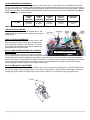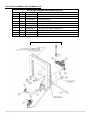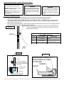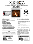
1
FULLVIEW RECTANGLE DIRECT VENT GAS FIREPLACE HEATER Model FV41-M INSTALLATION INSTRUCTIONS MANUAL DOCUMENT NO. FV41-M-IM-0511 WARNING: If the information in this manual is not followed exactly, a fire or explosion may result causing property damage, personal injury or loss of life. Do not store or use gasoline or other flammable vapors and liquids in the vicinity of this or any other appliance. WHAT TO DO IF YOU SMELL GAS Open windows. Do not touch electrical switches. Do not try to light any appliance. Extinguish any open flame. Do not use the phone in your building. Immediately call your gas supplier from a neighbor's phone. Follow the gas supplier’s instructions. If you cannot reach your gas supplier, call the fire department. Installation and service must be performed by a qualified installer, service agency or the gas supplier. WARNING Do NOT use this appliance if any part has been under water. Immediately call a qualified service technician to inspect the appliance and to replace any part of the control system and any gas control, which has been under water. 1|P age AVERTISSEMENT : Assurez-vous de bien suivre les instructions donné dans cette notice pour réduire au minimum le risque d’incendie ou pour éviter tout dommage matéeriel, toute blessure ou la mort. Ne pas entreposer ni utiliser d'essence ni d'autres vaperurs ou liquides inflammables dans le voisinage de cet appareil ou de tout autre appareil. QUE FAIRE SI VOUS SENTEZ UNE ODEUR DE GAZ: Ne pas tenter d'allumer d'appareil. Ne touchez à aucun interrupteur. Ne pas vous servir des téléphones se trouvant dans le batiment où vous vous trouvez. Appelez immédiatement votre fournisseur de gaz depuis un voisin. Suivez les instructions du fournisseur. Si vous ne pouvez rejoindre le fournisseur de gaz, appelez le service dos incendies. L'installation et service doit être exécuté par un qualifié installer, agence de service ou le fournisseur de gaz. INSTALLER: Leave this manual with the appliance. CONSUMER: Retain this manual for future reference. INSTALLATEUR : Laissez cette notice avec l’appareil. CONSOMMATEUR : Conservez cette notice pour consultation ultérieure. SAFETY AND WARNING INFORMATION FOR YOUR SAFETY A qualified installer, service agency, or the gas supplier must perform installation and service. Do not store or use gasoline or other flammable vapors and liquids in the vicinity of this or any other appliance. WARNING Do not operate this appliance with the glass removed, cracked or broken. A licensed or qualified person should do replacement of glass. AVERTISSEMENT. Ne pas utiliser l’appareil si le panneau frontal en verre n’est pas en place, est craqué ou brisé. Confiez le remplacement du panneau à un technicien agréé. WARNING Mendota gas fireplaces are heat producing appliances. Do not burn wood, paper or other materials in this fireplace. This fireplace is designed as a supplement heat source. It is advisable to have an alternative primary heat supply. WA In the Commonwealth of Massachusetts: Installation must be performed by a licensed plumber or gas fitter; A CO detector shall be installed in the room where the appliance is installed. WARNING: Improper installation, adjustment, alteration, service or maintenance can cause injury or property damage. Refer to this manual. For assistance or additional information consult a qualified installer, service agency or the gas supplier. This appliance may be installed in an aftermarket permanently located, manufactured (mobile) home (USA Only), where not prohibited by local codes. This appliance is only for use with the type(s) of gas indicated on the rating plate. This appliance is not convertible for use with other gases, unless a certified kit is used. Cet appareil peut être installé dans un maison préfabriquée (mobile) déjà installée à demeure si les règlements locaux le permettent. Cet appareil doit être utilisé uniquement avec les types de gas indiqués sur la plaque signalétique. Ne pas l’utiliser avec d’autres gas sauf si un kitde conversion certifié est installé. The installation must conform with local codes or, in the absence of local codes, with the current National Fuel Gas Code, ANSI Z223.1 (NFPA 54) or CAN/CGA B149.1 Installation Code. Installer l'appareil selon les codes ou règlements locaux, ou, en l'absence de tels règlements, selon les Codes d'installation CAN/CGA-B149. Do not use this appliance if any part has been under water. Immediately call a qualified service technician to inspect the heater and to replace any part of the control system and any gas control which has been under water". «Ne pas se servir de cet appareil s'il a été plongé dans l'eau, complètement ou en partie. Appeler un technicien qualifié pour inspecter l'appareil et remplacer toute partie du système de contrôle et toute commande qui ont été plongés dans l'lau READ and UNDERSTAND all instructions carefully before starting the appliance. FAILURE TO FOLLOW these instructions may result in a possible fire hazard and will void the warranty. Any safety screen or guard removed for servicing must be replaced before operating this appliance. Tout écran ou protecteur retiré pour permettre l’entretien de l’appareil doit être remis en place avant de mettre l’appareil en marche. READ and UNDERSTAND all instructions carefully before starting the appliance. FAILURE TO FOLLOW these instructions may result in a possible fire hazard and will void the warranty. Any safety screen or guard removed for servicing must be replaced before operating this appliance. Tout écran ou protecteur retiré pour permettre l’entretien de l’appareil doit être remis en place avant de mettre l’appareil en marche. THIS UNIT IS NOT FOR USE WITH SOLID FUEL. Installation and repair should be PERFORMED by a qualified service person. The appliance and venting system should be INSPECTED before initial use and at least annually by a professional service person. More frequent cleaning may be required due to excessive lint from carpeting, bedding, material, etc. It is IMPERATIVE that the unit’s control compartment, burners, and circulating air passageways ARE KEPT CLEAN to provide for adequate combustion and ventilation air. Always KEEP the appliance clear and free from combustible materials, gasoline, and other flammable vapors and liquids. NEVER OBSTRUCT the flow of combustion and ventilation air. Keep the front of the appliance CLEAR of all obstacles and materials for servicing and proper operation. 2|P age Due to high temperature, the appliance should be LOCATED out of traffic areas and away from furniture and draperies. En raison des températures élevées, l’appareil devrait être installé dans un endroit où il y a peu de circulation et loin du mobilier et des tentures. Clothing or flammable material SHOULD NOT BE PLACED on or near the appliance. On ne devrait pas placer de vêtements ni d’autres matières inflammables sur l’appareil ni à proximité. Children and adults should be ALERTED to the hazards of high surface temperature and should STAY AWAY to avoid burns or clothing ignition. Les enfants et les adultes devraient être informés des dangers que posent les températures de surface élevées et se tenir à distance afin d’éviter des brûlures ou que leurs vêtements ne s’enflamment. Young children should be CAREFULLY SUPERVISED when they are in the same room as the appliance. Toddlers, young children and others may be susceptible to accidental contact burns. A physical barrier is recommended if there are at risk individuals in the house. To restrict access to a fireplace or stove, install an adjustable safety gate to keep toddlers, young children and other at risk individuals out of the room and away from hot surfaces. “Les jeunes enfants devraient être surveillés étroitement lorsqu’ils se trouvent dans la même pièce que l’appareil. Les tout petits, les jeunes enfants ou les adultes peuvent subir des brûlures s’ils viennent en contact avec la surface chaude. Il est recommandé d’installer une barrière physique si des personnes à risques habitent la maison. Pour empêcher l’accès à un foyer ou à un poêle, installez une barrière de sécurité; cette mesure empêchera les tout petits, les jeunes enfants et toute autre personne à risque d’avoir accès à la pièce et aux surfaces chaudes. These units MUST use one of the vent systems described in the Installing Your Fireplace section of the Installers Guide. NO OTHER vent systems or components MAY BE USED. This gas fireplace and vent assembly MUST be vented directly to the outside and MUST NEVER be attached to a chimney serving a separate solid fuel-burning appliance. Each gas appliance MUST USE a separate vent system. Common vent systems are PROHIBITED. If the vent-air intake system is disassembled for any reason, reinstall per the instructions provided for the initial installation. The vent system assembly for this fireplace must be periodically examined by a qualified service agency. INSPECT the external vent cap on regular basis to make sure that no debris is interfering with the airflow. The flow of combustion and ventilation air not to be obstructed DO NOT abuse the glass door by striking the glass, slamming the door shut, etc. Use only authorized parts and materials obtained from Johnson Gas Appliance Company when replacing defective or damaged glass. DO NOT USE abrasive cleaners on the glass door assembly. DO NOT ATTEMPT to clean the glass door when it is hot. Turn off the gas before servicing this appliance. It is recommended that a qualified service technician perform an appliance check-up at the beginning of each heating season. DO NOT place furniture or any other combustible household objects within 36 inches of the fireplace front. 3|P age Contents SAFETY AND WARNING INFORMATION ............................................................................................................................. 2 SPECIFIC REQUIREMENTS FOR THE COMMON WEALTH OF MASSACHUSETTS ....................................................... 5 FV41-M FULL VIEW GAS FIREPLACE DIMENSIONS .......................................................................................................... 6 TECHNICAL SPECIFICATIONS FOR FV41-M-M .................................................................................................................. 7 BUILDING PERMIT AND INSTALLATION INSPECTION APPROVAL REQUIREMENTS ................................................... 8 GENERAL APPLIANCE SPECIFICATIONS ........................................................................................................................... 9 MANTEL CLEARANCES ...................................................................................................................................................... 10 CLEARANCES TO COMBUSTIBLES FROM APPLIANCE SURFACES ............................................................................. 11 PLANNING THE INSTALLATION ......................................................................................................................................... 12 ROUGH FRAMING DIMENSIONS ....................................................................................................................................... 13 FRAMING DEPTH AND FINISHING GUIDES ...................................................................................................................... 14 FINISHING MATERIALS INSTALLATION ............................................................................................................................ 15 HEARTH PROTECTION PAD REQUIREMENTS ................................................................................................................ 16 GENERAL INFORMATION ................................................................................................................................................... 17 GAS SUPPLY REQUIREMENTS ......................................................................................................................................... 18 GAS PRESSURE REQUIREMENTS .................................................................................................................................... 19 GENERAL INSTALLATION INSTRUCTIONS ...................................................................................................................... 20 GENERAL FLUE VENTING INSTRUCTIONS...................................................................................................................... 21 EXTERIOR VENT LOCATIONS AND RESTRICTIONS ....................................................................................................... 22 FLUE VENTING COMPONENTS IDENTIFICATION ........................................................................................................... 23 FV41-M MASTER FLUE VENTING REQUIREMENTS CHART .......................................................................................... 24 APPROVED VENT SYSTEMS ............................................................................................................................................. 26 INSTALLATION CHECK OFF LIST ...................................................................................................................................... 34 LIGHTING CHECK OFF LIST ............................................................................................................................................... 34 FV-41-M BURNER MEDIA INSTALLATION INSTRUCTIONS ............................................................................................. 35 FLAME APPEARANCE ADJUSTMENT ............................................................................................................................... 35 TROUBLE SHOOTING THE FV41-M FIREPLACE & MAINTENANCE INFORMATION..................................................... 36 MAINTENANCE .................................................................................................................................................................... 37 NATURAL TO LP GAS CONVERSION ................................................................................................................................ 38 LP GAS PRESSURE REQUIREMENTS .............................................................................................................................. 41 FV41-M VALVE ASSEMBLY REPLACEMENT PARTS ....................................................................................................... 43 FV41-M GAS IGNITION SYSTEM WIRING DIAGRAM........................................................................................................ 44 GLASS FRAME ASSEMBLY REPAIR AND REPLACEMENT ............................................................................................. 45 LISTING LABEL INFORMATION .......................................................................................................................................... 46 MENDOTA WARRANTY QUALIFICATION & SERVICE REFERENCE FORM .................................................................. 47 MENDOTA EXTENDED LIFETIME PROTECTION AND LIMITED WARRANTY ................................................................ 50 4|P age Specific Requirements for the Common Wealth of Massachusetts The information in this section applies to all installations performed in the Common Wealth of Massachusetts only. a) For all side wall horizontally vented gas fueled equipment installed in every dwelling, building or structure used in whole or in part for residential purposes and where the side wall exhaust vent termination is less than seven (7) feet above grade, the following requirements shall be satisfied: 1. If there is no carbon monoxide detector with an alarm already installed in compliance with the most current edition of NFPA 720, NFPA 70 and the Massachusetts State Building code in the residential unit served by the side wall horizontally vented gas fueled equipment, a battery operated carbon monoxide detector with an alarm shall be installed in compliance with the most current edition of NFPA 720. NFPA 70 and the Massachusetts State Building Code. 2. In addition to the above requirements, if there is not one already present, a carbon monoxide detector with an alarm and a battery backup shall be installed and located in accordance with the installation requirements supplied with the detector on the floor level where the gas equipment is installed. The carbon monoxide detector with an alarm shall comply with 527 CMR, ANSI/UL 2034 Standards or CSA 6.19 and the most current edition of NFPA 720. In the event that the requirements of this subdivision cannot be met at the time of the completion of the installation of the equipment, the installer shall have a period of thirty (30) days to comply with this requirement; provided, however, that during said thirty (30) day period, a battery operated carbon monoxide detector with an alarm shall be installed in compliance with the most current edition of NFPA 720, NFPA 70 and the Massachusetts State Building Code. In the event that the side wall horizontally vented gas fueled equipment is installed in a crawl space or an attic, the carbon monoxide detector may be installed on the next adjacent habitable floor level. Such detector may be a battery operated carbon monoxide detector with an alarm and shall be installed in compliance with the most current edition of NFPA 720, NFPA 70 and the Massachusetts State Building Code. 3. A metal or plastic identification plate shall be permanently mounted to the exterior of the building at a minimum height of eight (8) feet above grade directly in line with the exhaust vent terminal for the horizontally vented gas fueled heating appliance or equipment. The sign shall read, in print size no less than one-half (1/2) inch in size, “GAS VENT DIRECTLY BELOW, KEEP CLEAR OF ALL OBSTRUCTIONS” 4. A final inspection by the state or local gas inspector of the side wall horizontally vented equipment shall not be performed until proof is provided that the state or local electrical inspector having jurisdiction has granted a permit for installation of carbon monoxide detectors and alarms as required above. (b) EXEMPTIONS: The following equipment is exempt from 248 CMR 5.08(2) (a) 1 through 4: 1. The equipment listed in Chapter 10 entitled “Equipment Not Required To Be Vented” in the most current edition of NFPA 54 as adopted by the Board; and 2. Product Approved side wall horizontally vented gas fueled equipment installed in a room or structure separate from the dwelling, building or structure used in whole or in part for residential purposes. (c) When the manufacturer of Product Approved side wall horizontally vented gas equipment provides a venting system design or venting system components with the equipment, the instructions for installation of the equipment and the venting system shall include: 1. A complete parts list for the venting system design or venting system; and 2. Detailed instructions for the installation of the venting system design or the venting system components. (d) When the manufacturer of a Product Approved side wall horizontally vented gas fueled equipment does not provide the parts for venting the flue gases, but identifies “special venting systems”, the following shall be satisfied: 1. The referenced “special venting system” instructions shall be included with the appliance or equipment installation instructions; and 2. The “special venting systems” shall be Product Approved by the Board, and the instructions for that system shall include a parts list and detailed installation instructions. (e) 5|P age A copy of all installation instructions for all Product Approved side wall horizontally vented gas fueled equipment, all venting instructions, all parts lists for venting instructions, and/or all venting design instructions shall remain with the appliance or equipment at the completion of the installation. FV41-M FULL VIEW GAS FIREPLACE DIMENSIONS OVERALL APPLIANCE DIMENSIONS AND FEATURES 20 9/16 in 19 5/8 in 19 3/16 in 9 1/16 in 10 1/8 in 19 3/16 in 40 3/8 in 19 3/16 in 39 1/4 in 8 1/16 in 8 1/16 in 19 5/8 in 6 3/8 in 35 in 43 1/16 in 36 3/16 in 4 7/8 in 13 13/16 in 23 15/16 in 43 1/16 in 32 1/2 in 4 7/8 in ACCENT LIGHT HOUSING 5"X8" COAXIAL VENT STARTER COLLAR HEAT TRANSFER DUCTS CONNECTION PORTS 5"x8" COAXIAL STARTER COLLAR LH LIFT HANDLE LIFT HANDLE VISIBLE GLASS AREA 26-1/4" X 29-1/2" [775 sq. in.] CONTROLS ACCESS & INSPECTION PLATE Serial # and Lighting Instructions PlateS STANDING PILOT LIGHT SWITCH GAS SUPPLY INLET (1/2"MNPT) FRONT BURNER AIR SHUTTER CONTROL CONTROLS HARNESSES EXIT GAS TRAIN, IGNITION SYSTEM, RH BLOWER INSPECTION COVER 110VAC INLET 6|P age EXHAUST DAMPER ADJUSTMENT REAR BURNER AIR SHUTTER CONTROL LH FRAMING ATTACH BRACKETS RH BLOWER INSPECTION COVER RH FRAMING ATTACH BRACKETS TECHNICAL SPECIFICATIONS FOR FV41-M MODEL FV41-M BTUH. (MODEL FV41-M) BTUH. (MODEL FV41-M) High Fire - Adjustable to - Low Fire NAT. GAS LP GAS 29,000 29,000 18,000 22,000 NOTE: LPG CONVERSION KIT, #New #, MUST BE PURCHASED SEPARATELY TO CONVERT TO BURN LPG IN THIS FIREPLACE. MAIN ORIFICE [0-2000ft (610 m)]: #38 –: #52 LP ........................ [2000-4500ft (610-1370 m)]: #39 NG - #53 L.P. OVERALL EFFICIENCY: [AFUE: 68.0% NG, 71.2% LPG]; [P.4: 73.9% NG, 80.2% LPG] CO-AXIAL DIRECT VENT FLUE: .......... 5" INNER, 8" OUTER TOTAL WEIGHT: ................................... 225 POUNDS SAFETY: ................................................ AGA/CECERTIFIED IPI AUTO ELECTRONIC IGNITION SYSTEM ACTIVATED WITH THERMOSTATIC REMOTE CONTROL. APPLIANCE CERTIFICATION AND TESTING AGENCY INTERTEK TESTING SERVICES, ICBO#AA647-4 Certified under ANSI Z21.88 (2009) CSA 2-33 (2009) “Vented Gas Fireplace Heaters" not for use with solid fuel. Approved for bedroom installations and mobile homes. UL307B approved for "mobile homes, after first sale of home, not for recreational vehicles." GAS INLET: 1/2" N.P.T. GAS REQUIREMENTS .......................... SUPPLY PRESSURE: NAT. GAS: 7" W.C. (5" W.C. MIN., 11" W.C. MAX.) L.P. GAS: 11.0" W.C. (11" W.C. MIN., 13" W.C. MAX.) ELECTRICAL REQUIREMENTS ........... 115 VOLT, LESS THAN 1.5 amps (for blower operation only) APPROVED VENT SYSTEMS ............... DURAVENT, SELKIRK, AMERIVENT, SECURITY MINIMUM CLEARANCES TO COMBUSTIBLE CONSTRUCTION UNIT TO FLOOR 0in. (0mm) UNIT TO ENCLOSURE SIDEWALL 1/2in. (13mm) UNIT TO ENCLOSURE BACK WALL 1/2in. (13mm) UNIT BOTTOM TO ENCLOSURE CEILING 48-1/2in. (123 cm) UNIT BOTTOM TO ROOM CEILING 72 in. (1829 mm) 8” MANTLE ABOVE DISCHARGE AIR OPENING 18 in. (457 mm) GLASS EDGE TO ADJACENT SIDEWALL VENT PIPE TOP TO COMBUSTIBLES VENT PIPE SIDES TO COMBUSTIBLES VENT PIPE BOTTOM TO COMBUSTIBLES 18in. (457 mm) 2in. (51mm) 1in. (25mm) 1in. (25mm) MINIMUM COMBUSTIBLE ROUGH FRAMING DIMENSIONS WIDTH = 42-1/2” (108cm) HEIGHT = 47” (110cm) DEPTH = 19-3/16” (49cm) THIS FIREPLACE INCLUDES A SEALED COMBUSTION SYSTEM, 8-PIECE CERAMIC FIBER LOG SET & COALS, FIREBRICK LINED FIREBOX, NEO-CERAM GLASS, ELECTRONIC IGNITION SYSTEM, DUAL BLOWERS, AGA CERTIFIED SAFETY SYSTEM, ACCENT LIGHT and THERMOSTATIC REMOTE CONTROL. OPTIONS: BLACK, VINTAGE IRON, SWEDISH NICKEL, ANTIQUE GOLD, ANTIQUE COPPER HOMESTEAD & WILLOW DOORS, DUCHESS STAINED GLASS FRONT, BOULEVARD DOORS, SERENADE AND PORTRAIT TRIMS and other accessories. CAUTION THESE INSTRUCTIONS ARE TO REMAIN WITH THE HOMEOWNER. This appliance may be installed in an aftermarket, permanently located, manufactured home (USA only) or mobile home, where not prohibited by local codes. This appliance is only for use with the type(s) of gas indicated on the rating plate. NOTE: This installation must conform to local codes. In the absence of local codes, you must comply with the National Fuel Gas Code, ANSI Z223.1-latest edition in the U.S.A. and the Natural Gas and Propane Installation Code, CSA B149 Installation Codes in Canada. WARNING: Do not operate this appliance with the glass removed, cracked or broken. A licensed or qualified person should do replacement of glass. HIGH ALTITUDE INSTALLATION INFORMATION: Prior to installing at altitudes higher than 7500, please contact the Mendota technical service department for specific venting requirements and venting restrictions. 7|P age CONGRATULATIONS You are the owner of a world-class heat producing gas direct vent sealed combustion fireplace. This elegant, highly efficient Fireplace will be a constant source of comfort and fascination. It will be the focal point of beauty and interest in your home. This Mendota Gas Fireplace is a true heating appliance incorporating modern aesthetics of fire viewing with the controllability and fuel efficiency of a home gas furnace. Of particular interest is the low fuel consumption and brilliant fire viewing afforded by the high efficiency combustion system. Carefully read the following instructions prior to actual installation. Proper Mendota Gas Fireplace installation and operation will give you years of safe, trouble free comfort and enjoyment. If you have any questions regarding installation or operation of your Mendota Fireplace please contact your local dealer. ...CAUTION... Due to high temperatures, the Fireplace should be located out of traffic and away from furniture and draperies. Children and adults should be alerted to the hazards of high surface temperature and should stay away to avoid burns or clothing ignition. Young children should be carefully supervised when they are in the same room as the Mendota Gas Fireplace. Clothing or other flammable material should not be placed on or near the Fireplace. Any safety screen or guard removed for servicing an appliance must be replaced prior to operating this appliance. The Mendota Gas Fireplace is a powerful and efficient heating unit. It has been designed as a major source of supplemental heat. As with any mechanical appliance there can be component shut downs. It is advisable to have an alternate heat supply. Installation, repair and any adjustments to logs or burner must be done by a qualified service person. The appliance should be inspected before use and at least annually by a professional service person. More frequent cleaning may be required due to excessive lint from carpeting, bedding material, carbon build-up, etc. It is imperative that control compartments, burners and circulating air passageways of the appliance be kept clean. The burner and pilot flames and logs should be visually checked periodically. DO NOT use this appliance if any part has been under water or exposed to moisture corrosion. Immediately call a qualified service technician to inspect the Fireplace and replace any part of the control system and any gas control, which has been under water. DO NOT use this fireplace if the burner does not light immediately. Turn unit off and call Mendota approved service person if there is any delay in burner light off. It is Johnson Gas Appliance Company's policy that no responsibility is assumed by the Company or by any of its employees or representatives for any damages caused by an inoperable, inadequate, or unsafe condition which is the result, either directly or indirectly, of any improper operation, installation or servicing procedures. Building Permit and Installation Inspection Approval Requirements All installations of Mendota Fireplaces and Inserts must comply with all the requirements stated in this Installation and Operating Instructions Manual. The Dealer and/or installer must also obtain all required Building Permits and Inspection Approval from the local building inspection department or the local body having jurisdiction. In order to validate warranty coverage, Mendota may require facsimile copies of the Building Permit and Inspection Approval forms. Failure to provide adequate proof that the installation conforms to all local requirements and the requirements stated in the Installation and Operating Instructions Manual will void all applicable warranty. INSTALLER: THESE INSTRUCTIONS ARE TO REMAIN WITH HOMEOWNER. HIGH ALTITUDE INSTALLATION INFORMATION: Prior to installing at altitudes higher than 7500, please contact the Mendota technical service department for specific venting requirements and venting restrictions. 8|P age FV41-M-M DIRECT VENT GAS FIREPLACE GENERAL APPLIANCE SPECIFICATIONS FV-41 GAS DIRECT VENT FIREPLACE HIGH ALTITUDE INSTALLATION INFORMATION: Prior to installing at altitudes higher than 7500, please contact the SPECIFICATIONS Mendota technical service department GENERAL for specificAPPLIANCE venting requirements and venting restrictions. 1" MIN. 422 ROUGH FRAMING WIDTH 35-1/2" 493 4" 9" TO VENT PIPE CENTER 1" 328 1711" 16 19-1/2" MIN. DEPTH MINIMUM ROUGH FRAMING DIMENSIONS HEIGHT WIDTH DEPTH FROM UNIT BASE TO ROOM CEILING FROM UNIT BASE TO 8" MANTEL FROM UNIT BASE TO UNIT ENCLOSURE CEILING 16" TO GUIDE EDGE 11" 1716 47" 42-1/2" 19-1/2" ADJACENT WALLS: A wall perpendicular to and in front of this fireplace's glass door surface must be at least 16 inches from the side edges of the facing guide. A wall at 45° to the glass surface and starting at this Fireplace's outer edge is permitted. Projections behind this wall (in shaded area) are permitted. 493 4" 5" 7016 72" 48" 50" CEILING 24" MIN TO VINYL SOFFIT (18" MIN TO WOOD OR METAL SOFFIT) 8" MANTEL DEPTH AT HEIGHTS SHOWN NON-COMBUSTIBLE ZONE 72" MIN. TO ROOM CEILING 47" MIN. 47 48" MIN. UNIT BASE TO 8" MANTEL 47" MIN. ROUGH FRAMING HEIGHT 347 8" 1" MIN 422 OPENING WIDTH 18" 15" 14" 513 16" 11" 55" 7 16 7 " 48" 416 10" 9" 8" 7" 9" 316 31" 211" 8 16 4" 6" 5" 4" 3" 0" 0" 13 3 116" 15 18" 1 16" 2" 241" 2" 1" FIREPLACE FACE MUST BE COVERED W/ NONCOMBUSTIBLE FACING IN THIS AREA. A COMBUSTIBLE MANTEL ONLY ALLOWED IN THIS AREA IF INSTALLED OVER NON-COMBUSTIBLE FACING MATERIAL. 11" 616 12" DISTANCE FROM FIREPLACE FACE 9|P age 1" HEARTH PAD HEIGHT 12 (MIN R-1 RATING) IS REQUIRED! 13" 641" HEIGHT ABOVE CONVECTION AIR OPENING 8" 79" 781" 16 17" 16" 1" 198 50" MIN. UNIT FLOOR TO ENCLOSURE CEILING 42-1/2" TO CENTERLINE OF VENT CAP 18" min. Non-combustible Hearth protection required [SEE HEARTH PROTECTION PAD R-RATING, PAGE 12] CAUTION: The distance from floor level to the centerline of the vent cap is given based on Simpson Duravent GS components. If using vent components of other brands do not assume that the measurement given here is applicable. Verify the distance to centerline of vencap by measuring the components you will be using. NOTE: For every 1" this fireplace is raised off the floor, the non-combustible hearth protection pad may be reduced by 2". If this fireplace is raised off the floor more than 6", No hearth protection pad is required. NON COMBUSTIBLE FACING MANTEL CLEARANCES Mantel Clearances for this fireplace may be measured from the top of the convection air opening or the floor level of this fireplace. The location that is referenced normally to measure mantel clearances is the Top of the Convection Air Opening. For ease, however, measure up from the floor level of this fireplace. The chart and diagram, in this page, provide all the reference dimensional information necessary in determining the distance a combustible mantel may protrude out from the face surface of this fireplace. The Chart, at right, shows the Distance from Fireplace Face the combustible mantel may protrude outward at a Distance up From Floor Level of this Fireplace. If you prefer to take measurements from the Top of the Convection Air Opening, note that the Top of the convection air opening is 30 inches up from the floor level of this fireplace. WARNING: Make proper use of this chart. Do not compromise the specifications contained in this chart. Failure to adhere to proper clearances required to combustibles may cause spontaneous combustion of the mantel and may result in a fire causing property damage, personal injury or loss of life. Figure 1: Mantel Clearances FIREPLACE FACE MUST BE COVERED W/ NONCOMBUSTIBLE FACING IN THIS AREA. A COMBUSTIBLE MANTEL ONLY ALLOWED IN THIS AREA IF INSTALLED OVER NON-COMBUSTIBLE FACING MATERIAL. NON-COMBUSTIBLE ZONE 10 | P a g e CLEARANCES TO COMBUSTIBLES FROM APPLIANCE SURFACES Figure 2: Clearances to Combustibles 0" CLEARANCE FROM TOP STANDOFFS 1/2" CLEARANCE FROM BACK 1/2" CLEARANCE FROM SIDES 11 | P a g e PLANNING THE INSTALLATION When planning on appliance installation, it is necessary to determine the following information before installing: Where the appliance is to be installed. The vent system configuration to be used. Gas supply piping. Electrical Wiring. Framing and finishing details. Hearth Protection Pad Requirements. Whether accessories such as a wall switch, remote control, and ceiling fan are desired. Selecting Appliance Location When selecting a location for your appliance, it is important to consider the required clearances to walls. See Error! Reference source not found. and Figure 2: Clearances to Combustibles. Figure 3: Planning Installation 42-1/2 MIN. ROUGH FRAMING WIDTH 513 8" 19-1/2" MIN. 1" 254 18" 173 4" 1" 192 42-1/2" MIN. 42-1/2 MIN. ROUGH FRAMING WIDTH In addition to these dimensions, also reference: Mantel Clearances Section Framing Dimensions Section Venting Configuration Section 353 8" 703 4" WARNING FIRE RISK- ODOR RISK 12 | P a g e Install appliance on hard metal or wood surfaces extending full width and depth of this fireplace. An R-1 Rated Hearth Protection Pad [1-1/2” Thick Maximum] is required unless this fireplace is elevated. For every 1” this fireplace is elevated, you may reduce the hearth pad depth by 1”. If this fireplace is elevated 6” or higher no hearth protection pad is required. Do NOT install this fireplace directly on carpeting, vinyl or any combustible material other than wood. Construct chase to all clearance specifications in manual. Locate and install appliance to all clearance specifications in manual. ODOR RISK: DO NOT INSTALL ANY CEMENT BOARDS OF OTHER MATERIALS THAT CONTAIN POLYMER BASED FIBERS OR OTHER POLYMER MATERIALS. ROUGH FRAMING DIMENSIONS Rough Framing Dimensions The Rough Framing Dimensions must be maintained to allow this fireplace to slide into the fram0 ing cavity with a 90 elbow installed on the top starter collar. After the FV41-M Fireplace is inserted into the rough framed cavity, install one 2x4 on each side adjacent to the side of this fireplace’s body and one 2x4 on top of the top framing standoffs to close the air gap and to act as nailing studs for finishing materials. Minimum Rough Framing Dimensions A B C D E DESCRIPTION Width Height Depth Vent opening height Vent opening width DIMENSION (INCHES) 42-1/2” 47” 19-1/2” (19” Granite/Marble Facing) 10-3/4” 10-3/4” If the fireplace is to be recessed in a cavity deeper than 19-1/2”, all framing and finishing materials protruding past the front face of this fireplace must be of the NON-COMBUSTIBLE variety. Constructing the Appliance Chase A chase is a vertical box-like structure built to enclose this fireplace and its vent system. Vertical vents that run on the outside of a building may be, but are not required to be, installed inside a chase. Construction of the chase may vary with the type of building. These instructions are not substitutes for the requirements of local building codes. Local building codes MUST be adhered to. Chases should be constructed in the manner of all outside walls of the home to prevent cold air drafting problems. The chase should not break the outside building envelope in any manner. Wall, ceiling, base plate and cantilever floor of the chase should be insulated. Vapor and air infiltration barriers should be installed in the chase as per regional codes for the rest of the home. Additionally, in regions where cold air infiltration may be an issue, the inside surfaces of the chase may be sheet rocked and taped for maximum air tightness. To further prevent drafts, the fire stops should be caulked with high temperature caulk to seal the gaps. Gas line holes and other openings should be caulked with high temp caulk or stuffed with unfaced insulation. If the appliance is being installed on a cement slab, a layer of plywood may be placed underneath this fireplace to prevent conducting cold up into the room. Figure 4: FINALIZED Framing Dimensions REMOTE RECEIVER MOUNTING BOX (2-GANG BOX) 43-3/16" FINALIZED HEIGHT 42-1/2" FLOOR TO WALL THIMBLE CENTER 39-1/4" FINALIZED WIDTH 19-1/2" MIN. DEPTH 13 | P a g e FRAMING DEPTH and FINISHING GUIDES The framing depth for this fireplace is 19-1/2 inches. This is a fixed depth required for all installations, except a corner installation and for installations that use solid Granite or Marble slabs as fascia materials. For corner installations, see figures 1 and 4. OUTER FINISHING GUIDES (TOP, L & R) For installing solid Granite or Marble slabs as fascia material, reduce the framing depth by ½” then install ½” thick drywall on the framing studs so that the drywall is flush with the front face of this fireplace. Install the Granite or Marble slab so that it adheres to the face of the fireplace and the drywall. Finishing Guides Two sets of Finishing Guides are INNER FINISHING supplied with this fireplace: One set GUIDES(TOP, L &R) is called the Outer Guide and the other set is called the Inner Guide. Both guides protrude out 1” from the face of this fireplace. Both guides are factory secured using screws and may be removed if not needed or may be permanently attached using 1/8” rivets that are supplied with this fireplace. Inner Guide: Identify the Inner Finishing Guides (Top, Left and Right). These guides should be used as a guide for finishing materials if you are planning to install this fireplace as a “FULL VIEW” without any decorative front or if you are planning to install a “BOULEVARD DOOR KIT”, “DUCHESS STAINED GLASS OVERLAY”, “PORTRAIT GLASS FRAME OVERLAY” or a “SERENADE GLASS FRAME OVERLAY”. Remove and discard the Outer Guides (Top and sides) if you plan to use the Inner Guides. DECORATIVE FRONT TYPE FULL VIEW/ NO FRONT BOULEVARD DOOR KIT DUCHESS OVERLAY SERENADE OVERLAY PORTRAIT OVERLAY WILLOW DOOR KIT HOMESTEAD DOOR KIT INNER GUIDE USE USE USE USE USE DISCARD DISCARD OUTER GUIDE DISCARD DISCARD DISCARD DISCARD DISCARD USE USE Outer Guide: Identify the Outer Finishing Guides (Top, Left and Right). These guides should be used as a guide for finishing materials if you are planning to install a “HOMESTEAD” or “WILLOW” door kit on this fireplace. Remove and discard only the Inner Guides (Top and Sides only) if installing a “WILLOW” or “HOMESTEAD” door kit and you plan to use the Outer guides. 14 | P a g e FINISHING MATERIALS INSTALLATION All finishing materials that surround this fireplace’s rectangle profile must extend out from the face surface of this fireplace 1 inch. Tiles and Faux Rock If installing Tiles or Faux Rock, first install a ½” thick (minimum) Cement Board (Hardibacker or Durock Brand) over the face of the fireplace and framing members. Follow by applying Thinset mortar (no polymer additives) using ¼” square notched trowel on the cement board surface. Finally, install tile to reach a finish material depth of 1 inch. WARNING OF ODOR RISK: Cement Boards used shall not contain any polymer based fibers or polymer materials. Marble and Granite Slabs If installing Marble or Granite slabs as fascia materials, specify that the inner edges that will be adjacent to the Glass Door are polished. Rough Framing should be created at 19” depth with the front surface of this fireplace protruding out ½” from the framing surface. Install 1/2'” thick drywall on framing members so that its outer surface is flush with the front face of this fireplace. Attach Marble or Granite slabs to face of unit and to drywall surface using adhesive that does not offgas when hot. In the area defined as “NONCOMBUSTIBLE ZONE” [FIGURE 7], only NONCOMBUSTIBLE MATERIALS ARE ALLOWED. When this fireplace is installed in a framed cavity that is 19-1/2” deep, the facing material finishing guide will protrude out into the room 1 inch. Build finishing materials to 1 inch thickness and use the built-in guides for edge alignment of fascia material. Consult section “FRAMING DEPTH and FINISHING GUIDES”. DETAIL B SCALE 0.26 : 1 1.00 INCH FACE OF FV-41 WARNING OF ODOR RISK Cement Boards used shall NOT contain any polymer based fibers or polymer materials. 1" FINISHING GUIDE WARNING: See Figure 6. The cross hatched areas labeled as “NONCOMBUSTIBLE ZONE” must be covered with noncombustible finishing materials that is 1-inch thick, minimum. DO NOT ALLOW COMBUSTIBLE MATERIALS TO ENCROACH IN THIS AREA! NON-COMBUSTIBLE ZONE [ALL HATCHED AREAS] Figure 6: NON COMBUSTIBLE ZONE [ALL HATCHED AREAS] 15 | P a g e HEARTH PROTECTION PAD REQUIREMENTS Hearth Protection R Rating: MINIMUM R-1 IS REQUIRED. USE OF A ½” THICK (MINIMUM) CEMENT BOARD (Hardibacker, Wonderboard or other brand) plus ¼” thick mortar (ThinSet type) plus ¼” thick ceramic tile exceed the R-1 requirement. Use this as a reference, if in doubt. Natural Stones of 1” or greater thickness also exceed R-1 rating. All hearth pads must be non-combustible (metal, brick, stone, or mineral fiberboard). Do not use any combustible material to protect the floor in front of this fireplace. For the FV41-M, the hearth protection pad must be rated at R-1 minimum AND it must extend 18 inches in front of the fireplace face if the FV41-M fireplace is installed at floor level. Use the following procedure to determine if a hearth pad meets the requirements listed in this manual. Find the available values, R, K or C and follow the formulae below to arrive at a R value. R-value = Thermal Resistance K-value = Thermal Conductivity C-value = Thermal Conductance Convert the specification to R-value; a. If R-value is given, no conversion is needed. b. If K-value is given with for a thickness (t) in inches: 1 T ...( 1 divided by K , then multiplied by thickness). K 1 c. If C-value is given: R …(1 divided by C). C R Determine the R-value of the proposed hearth pad. For multiple layers, add R-values of each layer to determine overall R-value. If the overall R-value of the system is greater than R-1, then the proposed hearth pad is acceptable. Example: Required minimum R value for hearth protection pad is R=1. The proposed alternative is 1/4” tile with a C- factor of 1.25 over 1/8” mineral board with a K-factor of 0.29. Determine if the proposed layers will provide the minimum R=1 rating. Step A. Use formula to convert C-factor of the ¼” tile to R-value. R of the tile: R of mineral board: = 1/1.25 = 0.80 R 1 T K =1/0.29 x 0.125 = 0.431 Step C. Add R values of ¼” Tile and mineral board to get the Total R-value of proposed alternative: RTotal = Rtile + Rmineral board = 0.8 + 0.431 = 1.231. Step D. Compare proposed system R = 1.231 to required R of 1.0. Since R of proposed system is greater than the required R=1, the proposed system is acceptable. Figure 7: 16 | P a g e 1 C Step B. Use formula to convert K-factor of mineral board to Rvalue. Hearth Pad Guide- [Usage and Removal] This fireplace is shipped with a Hearth Pad Guide Installed. The purpose of the Hearth Pad Guide is to limit the height of the Hearth Pad during installations. DO NOT build a Hearthpad that is more than 1-1/2” thick. Doing so will not allow installation of decorative fronts on this fireplace. After the Hearthpad is built, remove the Hearth Pad guide and discard if you do not wish the guide to be visible. In some instances, you will want the guide left permanently, based on your aesthetic judgment. To remove the Hearth Pad Guide, first remove the Glass Frame. Identify the plastic Rivet heads inside the fireplace body. Use a sharp utility knife to pry or cut the plastic rivet head and rivet base. Lift the Hearth Pad Spacer upwards and remove. This fireplace may be installed in an elevated position by created an elevated deck and an appropriate framed enclosure. NOTE: This fireplace may be elevated but MUST allow a minimum of 72” distance between this fireplace’s floor level and the ceiling. PRY or CUT RIVET HEAD USING A SHARP EDGE. REPEAT FOR 4 RIVETS. R FRONT 1" MAX. THICK HEARTH PAD 12 (MIN R-1 RATING) IS REQUIRED! FIGURE 8 18" min. Non-combustible Hearth protection required [SEE HEARTH PROTECTION PAD R-RATING, PAGE 12] NOTE: For every 1" this fireplace is raised off the floor, the non-combustible hearth protection pad may be reduced by 2". If this fireplace is raised off the floor more than 6", No hearth protection pad is required. GENERAL INFORMATION Your Mendota Gas Fireplace has a state-of-the-art co-axial direct vent, sealed combustion system. This advanced and highly efficient system brings in outside air for combustion, has a separate exhaust vent and efficiently heats and re-circulates room air. The Mendota system maintains high air quality, maximizes efficiency and assures proper operation in today's "air-tight" homes. SAFETY AND STRUCTURAL CONCERNS: The FV41-M Fireplace must be installed and serviced by a Mendota approved serviceperson. Any adjustments to burner, pilot, logs or coal bed must be made by a Mendota approved service person. If pilot goes out, always wait five (5) minutes before attempting to relight pilot. VENTING REQUIREMENTS: This Mendota Fireplace can be vented using any available brand DIRECT VENT coaxial pipe (5”X 8”) off the top. Use only Mendota specified vents and vent caps when installing your fireplace. Closely follow venting locations, directions and requirements. Observe the restrictions relating to vent position on exterior of home (see Figure 12). Be sure all vent pipe sections are fully twist-locked and leak-proof. Be sure 1000º Silicate Stove Sealant is used on the inner pipe joints of all Simpson DuraVent pipe components and all adjustable pipe sections. The Mendota Direct Vent Fireplace may be placed within 18 inches of adjacent sidewalls. The fireplace may be placed directly on concrete or wood flooring. If the appliance is to be installed on carpeting, vinyl or other combustible material other than wood flooring, the appliance shall be installed on a metal or wood panel extending the full width and depth of the appliance. An 8” combustible mantel may be installed at a minimum of 18" above top of the heat outlet (48”) up from the floor level of this fireplace) and no more than 8" out from wall at that height. Non-combustible (marble, brick, stone, etc.) mantels can be installed at any desired height above the top convection air opening. Combustible Mantels of any depth with a sheet metal protector plate in its under-side may only be installed outside the “NON-COMBUSTILBE ZONE” above the top convection air opening. Never block off convection air openings or paths. Always use Mendota decorative fronts and Mendota approved vent systems and vent caps. A non-combustible hearth protector with a total insulation rating of R-1 is required when installing this fireplace directly on the floor and must extend a minimum of 18" in front of the fireplace. For every 1 inch the fireplace is raised off the floor, the depth of the hearth protector may be reduced by 2 inches. If fireplace is raised off the floor 6" or more, no hearth protector is required. HEATING PERFORMANCE: With its high heat output this Mendota Fireplace will heat a large area of your home if located properly to maximize heat/ air circulation. Air movement options for maximizing heat circulation that can be considered are the continuous operation of central heating furnace blowers or ceiling fans. The most efficient method for overall heat distribution within a single room is a ceiling fan. The heat output of the Fireplace can be reduced to a low 13,000 BTUH by turning off the Rear Burner and reducing flame height using the remote control. Blower can be turned down or turned off to reduce heat output. AESTHETIC CONSIDERATIONS: Burning or static fireplaces are a major aesthetic focus in any room. Locate your gas fireplace as you would a television set. The Mendota Hearth Gas Fireplace will be a continuing source of comfort and fascination. Corner installations will afford you the greatest potential for viewing in many rooms. We suggest installing this Mendota Fireplace a minimum of 12 inches above the floor by utilizing an elevated hearth. This fireplace may be installed in an elevated position as long as 72 in. minimum distance is provided between the floor level of this fireplace and the room’s ceiling surface. ELECTRICAL REQUIREMENTS: Electronic Ignition System, Dual Blowers and an Accent Light system are included in this Mendota Direct Vent Fireplace. These devices require constant electrical power except during power outages. A 115-volt electrical service must be supplied at the fireplace location at the time of installation, on the left side of this fireplace. It must be electrically grounded in accordance with local codes, or in their absence, with the current edition of the National Electric Code ANSI/NFPA 70. Use of a wall switch control in the power supplied to this fireplace is allowed. Thermostatic function is included in the Remote Control Transmitter. Therefore, no Thermostat wire is required. REMOTE CONTROL RECEIVER LOCATION AND MOUNTING REQUIREMENTS A remote control receiver, a double-gang box and a 10 foot long wire harness are supplied with this fireplace. Plan for mounting the doublegang box at 4 feet above floor level on the left side of this fireplace. Position remote receiver about 24 inches on the left side of the fireplace. Do not attempt to locate the receiver on the right side and do not route the 10 foot cable on top of this fireplace. The heat on top of this fireplace will damage the 10 foot cable if you route the cable to the right side. 17 | P a g e REMOTE RECEIVER MOUNTING BOX (2-GANG BOX) 43-3/16" FINALIZED HEIGHT 39-1/4" FINALIZED WIDTH GAS SUPPLY REQUIREMENTS Correct gas pressure and proper gas supply line sizing is imperative to the successful performance of your Mendota gas fireplace. Be sure the gas supplier or plumber carefully checks for correct gas pressure and gas line sizing when installing the fireplace. This Mendota Gas Fireplace comes equipped with a 1/2" N.P.T. Female inlet. Gas supply piping must enter the Fireplace cabinet on the left side. An approved manual shut-off ball valve, as required by local codes must be installed at an accessible location. The appliance and its individual shut-off valve must be disconnected from the gas supply piping system during any pressure testing of that system at test pressures in excess of ½ PSIG (3.5 kPa). GAS LINE INLET 1/2" FNPT REQ'D It is critical to carefully check for gas leaks when hooking up the fireplace -- check with soap & water solution. Be sure to install "approved" flex gas line with brass-to-brass fittings to prevent gas leaks at connections. Gas supply piping must include a drip leg to eliminate the possibility of contaminants entering the gas train. Adhere strictly to local and national codes for entire installation. FRONT Figure 8: Gas Supply Correct gas pressure and proper gas supply line and Electrical Supply sizing is required. Inlets Locations GAS SUPPLY LINE SIZING 110VAC INLET 14-2 CABLE REQ'D The appliance must be isolated from the gas supply piping system by closing its manual shut-off ball valve during any pressure testing of the gas supply piping system at test pressures equal to or less than 1/2 PSIG (3.5 kPa). 915 16 1 1216 1441 A proper gas line diameter must be selected to run from the supply regulator to the Fireplace. Refer to the following table for proper gas pipe diameters. Strictly adhere to the correct pipe sizes. WARNING: Never use any type of pipe thread sealants or compounds on the seats of flare or compression connections. PIPE LENGTH (FEET) SCHEDULE 40 PIPE INSIDE DIA. TUBING, TYPE L OUTSIDE DIA. NAT. L.P. NAT. L.P. 0-10 1/2" (1.3 cm) 3/8" (1.0 cm) 1/2" (1.3 cm) 3/8" (1.0 cm) 10-40 1/2" (1.3 cm) 1/2" (1.3 cm) 5/8" (1.6 cm) 1/2" (1.3 cm) 40-100 1/2" (1.3 cm) 1/2" (1.3 cm) 3/4" (2.0 cm) 1/2" (1.3 cm) 100-150 3/4" (2.0 cm) 1/2" (1.3 cm) 7/8" (2.3 cm) 5/8" (1.6 cm) 150-200 3/4" (2.0 cm) 1/2" (1.3 cm) 7/8" (2.3 cm) 3/4" (2.0 cm) NOTE: Some areas allow coated stainless steel (CSST), copper tubing or galvanized pipe - check with local approval agencies and codes. NEVER use plastic pipe. GAS PRESSURE CHECKING REQUIREMENTS Inlet and manifold gas pressure checking taps are located on gas valve. Perform inlet and outlet pressure tests before completing the facing installation. Remove valve access cover box on left side of fireplace to access the gas valve and all control components. A qualified installer shall take pressure measurements at these ports to verify and set the correct inlet gas pressures during initial installation. Outlet gas pressures are factory-set and cannot be field adjusted. NOTE: Check for gas leaks with soap and water solution on all factory joints and field installed joints during first firing of this appliance. 18 | P a g e GAS PRESSURE REQUIREMENTS One of the main causes of operating problems with gas appliances can be improper gas pressure! Problems such as changes in flame color or configuration, gas pilot or burner outages, intermittent operation, changes in heat output, excessive burner noise, etc. are nearly always the result of changes in gas pressure or improper gas pressure at the time of the installation. The most important item to check during initial installation and the first thing to check when problems occur are the input and output gas pressures! Gas is normally supplied to a residence at 1/2 PSI (13" - 15" W.C.) (3 KPA). A pressure regulator is then placed outside the residence, near the gas meter, which drops this pressure to 7" W.C. (1.8 KPA) (Nat. Gas). This "inches to inches" regulator is of adequate capacity to service the gas appliances (such as dryer, furnace, etc.). If this regulator's capacity is not sufficient to add the Gas Fireplace, an additional "inches to inches" regulator must be installed for the Fireplace. EXCEPTION: Some codes allow 2-PSI (1.4KPA) supplies to enter the residence, in which case "pounds to inches" regulators are used. The following table provides information on correct gas pressure requirements. Be sure your gas supplier or plumber carefully follows this table. GAS PRESSURE REQUIREMENTS DESIRED INLET PRESSURE MINIMUM INLET PRESSURE MAXIMUM INLET PRESSURE MANIFOLD OUTLET PRESSURE AIR SHUTTER POSITION* NATURAL GAS 7.0" W.C. (1.75 kPa) 5.0" W.C. (1.12 kPa) 11" W.C. (2.61 kPa) 3.5" W.C. (0.87 kPa) 0 - 1/8 " OPEN (3 mm) L.P. GAS 11.0" W.C. (2.75 kPa) 11" W.C. (2.75 kPa) 13.0" W.C. (3.24 kPa) 10.0" W.C. (2.5 kPa) 1/4" OPEN MIN. (5 mm) NOTE: For altitudes above 2.000 feet some variations in air shutter settings may be required. Manifold pressure must be taken at the “OUTPUT PRESSURE" tap and inlet pressure at the "INLET PRESSURE" tap with the burner operating by a qualified installer. Perform pressure tests prior to installing facia material around this fireplace. Figure 9: Gas Valve Pressure Test Ports 19 | P a g e GENERAL INSTALLATION INSTRUCTIONS CAUTION: Each installation must conform to all local, state and national codes. Refer to the national fuel gas code and local zoning and code authorities for details on installation requirements. The Mendota Fireplace must be vented to the outside in accordance with the latest edition of the National Fuel Gas Code. In the absence of local codes, the installation must conform to the most current edition of the National Fuel Gas Code ANSI Z223.1, also known as NFPA 54. NOTE: The Mendota FV41-M Fireplace is approved for mobile home and bedroom installations. CAUTION: The Mendota FV41-M Fireplace may be installed in a manufactured (mobile) home after the first sale of the home. Manufactured home (mobile home) installation must conform with the Manufactured Home Construction and Safety Standard, Title 24 CFR, Part 3280, or, when such a standard is not applicable, the Standard for Manufactured Home Installations, ANSI A225.1/NFPA 501A, or CSA Z240.4-Gas Equipped Mobile Housing. Consult your local building official. Note: For mobile home installations unit must be bolted to the floor and properly grounded. The FV41-M Fireplace must be installed by a qualified service person. HIGH ALTITUDE INSTALLATION INFORMATION: Prior to installing at altitudes greater than 7500, please contact the Mendota technical service department for specific venting requirements and venting restrictions. 1. After selection of the desired fireplace location, prepare the rough opening using framing dimensions on page 10. Be sure to also prepare opening to allow for co-axial vent). 2. Check to make certain all venting requirements and locations are being followed. 3. This Fireplace is designed for installation into rough framing. NOTE: FRAMING MATERIAL ABOVE FIREPLACE MUST MAINTAIN CORRECT CLEARANCE TO FIREPLACE AND VENT PIPES. WARNING: One-inch clearance to sides & below and 3 inches clearance on top of horizontal vent sections and elbows are required. 4. NOTE: A removable panel in the enclosure for future visual inspection of flue connection is recommended. 5. Have an electrician install a 115-Volt supply to the junction box on lower left side of the fireplace cabinet. Connect wires using wire nuts. Make sure the grounding wires are properly connected and that the installation conforms to all local and national wiring codes. 6. Have gas supplier or qualified plumber install gas supply line to fireplace and connect to the ½” female connector. Be sure gas and plumbing instructions (see Page 18 and 19) and all local and national codes are carefully followed. IMPORTANT: Any safety screen, guard, glass, grill etc. removed for servicing this fireplace must be replaced prior to operating this fireplace. Figure 10: Junction Box BLOWER OPERATION The blower output can be regulated with the remote (included). NOTE: There will be a time delay in blower operation during "heat-up" (5 min.) and extended blower operation during "cool-down" of unit (12-1/2 min.). 110VAC INLET 14-2 CABLE REQ'D 915 16 1441 20 | P a g e GAS LINE INLET 1/2" FNPT REQ'D OPERATION DURING POWER OUTAGES The fireplace is designed to operate during power outages on back-up batteries. The blower and Accent Light will not operate during the power outage. Backup batteries are located inside the wallmounted remote receiver box. Change the batteries at least once a year. FRONT 1 1216 GENERAL FLUE VENTING INSTRUCTIONS The Mendota Fireplace must be vented using the Mendota approved vent system components. Approved brands of vent components include DuraVent, Amerivent, Selkirk and Security vent pipes and venting components. All warranties will be voided and serious fire, health or other safety hazards may result from any of the following actions: Installation by unauthorized personnel; installation of any damaged component; unauthorized modification of vent system; installation of any components not approved by Mendota; failure to meet all clearance requirements; failure to properly twist-lock and positively seal all components. Consult local building codes before beginning the installation. WARNING Always maintain required clearances (air spaces) to combustibles to prevent a fire hazard. Do not fill air spaces with insulation. Check installation instructions for minimum clearance requirements between the outer walls of the vent pipe and nearby combustible surfaces. Be sure to check the vent termination clearance requirements from decks, windows, soffit, gas regulators, air supply inlets, and public walkways, as specified in these installation instructions and local building codes. SAFETY PRECAUTIONS FOR THE INSTALLER: 1) Wear gloves and safety glasses for protection; 2) Exercise extreme caution when using ladders or on rooftops; and 3) Be aware of electrical wiring locations in walls and ceilings. This gas appliance and vent system must be vented directly to the outside of the building, and never attached to a chimney serving another solid fuel or gas burning appliance. Each direct vent gas appliance must have its own separate vent system. Common vent systems are prohibited. To assure proper venting performance of this high-performance Mendota Direct Vent Fireplace, it is critical that all brands of vent pipe sections are sealed tightly and leak-proof. This means that all pipe sections must be carefully rotated into the fully "twist-locked" position. We strongly recommend that fixed length pipe sections be used in place of telescoping sections whenever possible. Note: When using vent pipe and components that do not incorporate a fiberglass or graphite gasket at the inner exhaust tube joints, you must use Milpak 1000F silicate stove sealant (#65-06-00909). Aluminum foil tape may be used on the outer (air intake) pipe joint but is not mandatory. Local Codes may vary. Contact your dealer for proper materials. Do not separate telescoping sections. They must be used as complete assemblies. Figure 11: Twist-Lock Piping COMPONENT "TWIST-LOCK" CONNECTION PROCEDURE DuraVent and American Metals pipe and fittings are designed with special twist-lock connections. Twist-lock procedure is as follows: four (4) indentations, located on the female ends of pipes and fittings are designed to slide straight in to the male ends of the adjacent pipes and fittings, by orienting the four pipe indentations so that they match and slide into the four entry slots on the male ends. Push the pipe sections completely together then twist-lock one section clockwise, approximately ¼ turn until the two sections are fully locked. The female locking lugs will not be visible from the outside on the black pipe or fittings. They may be located by examining inside of the female ends. HIGH ALTITUDE INSTALLATION INFORMATION Prior to installing at altitudes higher than 7500, please contact the Mendota technical service department for specific venting requirements and venting restrictions. 21 | P a g e EXTERIOR VENT LOCATIONS AND RESTRICTIONS ALL MEASUREMENTS FROM CENTER-LINE OF VENT CAP - Vent Terminal A= B= - Air Inlet Figure 12:Supply Exterior Vent Clearance above grade, veranda, porch, deck, or balcony (*12 inches (30 cm) minimum). Vinyl surfaces require 24” min. Clearance to window or door that may be opened (*12 inches (30 cm) minimum. - Area where terminal is not permitted H= *Not to be installed above a meter/regulator assembly within 3 feet (90 cm) horizontally from the center-line of the regulator I= *Clearance to service regulator vent outlet *3 feet (92 cm) minimum. *Clearance to non-mechanical air supply inlet to building or the combustion air inlet to any other appliance. 12 inches (30 cm) minimum. J= C= *Clearance to permanently closed window (minimum 12 inches (30 cm) recommended to prevent condensation on window) D= *Vertical clearance to ventilated soffit located above the terminal from the center-line of the terminal 24” (60 cm) min. K= *Clearance to a mechanical air supply inlet 6 feet (1.8 m) minimum E= *Clearance to unventilated soffit 24” min (60 cm) min. L= † Clearance above paved side-walk or a paved driveway located on public property (*7 feet (2.1 m) minimum) F= Clearance to outside corner - 7 inches (18 cm). M= Clearance under veranda, porch, deck, or balcony (*12 inches (30 cm) minimum ‡) G= Clearance to inside corner - 12 inches (30 cm). Vinyl surfaces require 24” min (60 cm). N= Minimum 24” horizontal clearance to any surface, such as an exterior surface, for vertical terminations. † A vent shall not terminate directly above a sidewalk or paved driveway, which is located between two single-family dwellings and serves both dwellings. ‡ Only permitted if veranda, porch, deck, or balcony is fully open on a minimum of two sides beneath the floor. * As specified in CGA B1:19 Installation Codes (1991). Note: Local codes or regulations may require different clearances. Clearances are in accordance with local installation codes and the requirements of the gas supplier. Dégagement conforme aux codes d’installation locaux et aux exigences du foumisseunde gaz. 22 | P a g e FLUE VENTING COMPONENTS IDENTIFICATION DO NOT SEPARATE TELESCOPING SECTIONS. USE TELESCOPING SECTIONS AS COMPLETE ASSEMBLIES. HIGH ALTITUDE INSTALLATION INFORMATION: Prior to installing at altitudes higher than 7500, please contact the Mendota technical service department for specific venting requirements and venting restrictions. ITEM 1 2 3 4 5 6 7 8 9 10 11 12 13 14 15 DESCRIPTION 6" or 7” PIPE (DuraVent 6”/Amerivent 7”) 12" VENT STACK 24" VENT STACK 36" VENT STACK 48" VENT