1
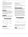
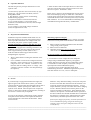
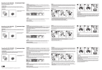
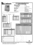
Installation manual for Powercaps
A. Upon reception of the Powercap
1- Inspect the Powercap for any damage that may
have occurred during transportation. Check the
enclosure for any dent or bent brackets.
2- Open the Powercap and check the construction for
any loose wire or nuts. Check capacitor cells
integrity (bent or dented cover).
3- If any damage is found, file a claim against the
transportation company and notify Power Survey for
RMA procedure. Do not use damaged Powercap or
compromised cells.
_____________________________________________________________________________________________
B. Mounting Information
3- Do not install immediately near heat source like oven,
1- Unless you ordered a NEMA 3R Powercap, your
Powercap is designed for indoor use (NEMA 1).
furnace and the like.
2- Powercap comes with mounting brackets and are
designed for mounting on walls. When you are
installing a Powercap you must make sure that you
leave minimum ventilation clearance recommended
by Power Survey (see image on right). All
adjacent equipment or others obstruction shall be
considered as walls or overhead. No more than
three barrier, including the floor or overhead shall
restrict free circulation of air.
_____________________________________________________________________________________________
C. Operating / Storage temperature and environment variables
Temperature need to be taken into account when you
store or operate a Powercap.
a.
b.
Storage temperature is the temperature of the
immediate area around the Powercap before it is
installed or when it is not operating.
c.
Operating temperature is the temperature of the
immediate area when the Powercap is energized. Use
the following procedure to determine operating
temperature:
1- The Powercap must have been in operation for the
last 24 hours before temperature is measured
2- The operating temperature must be determined by
taking the average of three readings taken as follow
(all 12 inches from the Powercap):
One thermometer level with top of the Powercap.
One thermometer 12 inches above bottom of
Powercap.
One thermometer midway between the two precedent
positions.
Operating temperature:
-40 F to +115 F, with natural convection cooling
Storage temperature:
-40 F to +185 F
Maximum altitude: 2000 Meters above sea level
Humidity: 0 – 95% non-condensing
_____________________________________________________________________________________________
_____________________________________________________________________________________________
D. Installation
Before installing: Make sure that the Powercap
nameplate voltage rating is suitable for operations at the
supply line voltage. Capacitors are capable of operation
at a maximum of 110 percent of nameplate rated
voltage (RMS, 60 Hz, including harmonics, but
exclusives of transients).
The installation of capacitors is regulated in the
National Electrical Code, article 460. Power Survey
meets all the requirements of the Code relative to
discharge resistors and over current protection.
Preferred connections for the terminal capacitors are
illustrated below:
Install at position 1
Position one being considered the ideal location.
Note that when the capacitor is placed between the
motor running over current protection (motor overload
relay heater coil) and the motor, less current will flow
through the overload relay and the motor running over
current heater coil will have to be changed to
compensate for the reduced current to the motor due to
the addition of the capacitor.
Install at position 2
Position two between the starter and thermal overload is
the second best choice on existing motor applications
when overload rating is higher than permitted by the
NEC code.
3) The motor is subject to repetitive switching, jogging,
inching or plugging
4) A multi-speed motor is used
5) A reversing motor is used
6) A high-inertia load may drive the motor
In any of theses cases the capacitors should be switched
with a contactor interlocked with the motor starter (see
position 3).
Installation directly on the power line
Powercap which are going to be installed for line
correction must be provided with conductors that are rated
at a minimum of 135% of the rated capacitor current
(NEC Section 460.8, see cable size table). Also, over
current protection and disconnects (165% current) or
circuit breakers (150% rated current, which are
manufacturers minimum recommended derated sizes).
Use wire size as recommended on the wired size table.
Power leads inside a capacitor case should be as straight
as possible and without kinks or loops. Lead length
should be such that no strain is applied to the power lead
connector. Power leads shall be firmly clamped in
connectors by tightening connector bolts. Wire lead
strands should not move in connector when the lead is
moved from side to side by hand. Loose connections will
cause terminal overheating and possible early failure of
capacitor unit.
Overall view of the capacitor on the line
Preferred connections for Powercaps
Install at position 3
As per IEEE standard, never connect the capacitor
directly to the motor when:
The Powercap must be connected to any location through
a disconnect device and have over current protection. All
customers wiring must be protected as it passed through
the capacitor case with a cable or conduit connector or
insulating grommet.
Grounding
1) Solid state starters are used
All capacitors are provided with ground connector lugs in
2) Open-transition starting us used
to facilitate grounding as per NEC Article 250.
_____________________________________________________________________________________________
_____________________________________________________________________________________________
E. Capacitor and Fuses
The following are the principal characteristics of our
capacitor cells:
1. Power Survey capacitor come in two forms, dry type
and oil type. Oil type fluid is non-PCB, non-toxic
biodegradable fluid.
2. The dielectric system consists of self healing,
metallized Polypropylene.
3. Capacitors tolerance is between 0% and 15%.
4. Over current tolerance is 135% rated current
continuous, include harmonic currents (150% for high
harmonics cells).
5. Over voltage is 110% rated voltage continuous
(120% for high harmonic cells).
6. Each cell has a built-in interrupter device to remove the
capacitor from the line before internal pressures can cause
the case to rupture. Threshold is 10 kA.
Power Survey capacitors are furnished with correctly sized
fuses with interrupting ratings of 100 KAIC or 200 KAIC.
Current ratings of fuses have been selected so that the fuses
will handle normal inrush current and protect major internal
fault conditions. It is not recommended to substituting fuses
with different ratings than the factory installed fuses.
_____________________________________________________________________________________________
F. Inspection and maintenance
Installation inspection should be made within 8 to 24
hours after capacitors have been energized and during
the first period of maximum over voltage which will
occur when your power system is lightly loaded.
NEVER manipulate a capacitor that has juste been
switched off since they remain energized. The
capacitors are equipped with a discharge resistance (330
kOHM for Aerovox capacitors) that will de-energize
these in approximately 1 minute (600v or less).
ALWAYS take the following precautions before
manipulating the capacitors:
a.
b.
Wait 1 minute before touching the terminals of the
capacitor.
Use a voltmeter to measure the voltage between the
terminals. If the capacitors are not completely deenergized leave the voltmeter connected to the
terminal until the reading shows no voltage. (The
voltmeter’s internal resistance will help discharge
the capacitor).
Measuring capacitor integrity
In order to determine capacitor integrity, measure of voltage
and current on each phase should be taken to determine that:
1) Phase voltages are balanced and below the maximum
voltage rating of the capacitor
2) Phase current are balanced
3) Operating current does not exceed 135% of the rated
value of the unit or assembly.
Do not exceed 135% of rated KVAR current
This kVAR current shall include:
1- Current due to excess voltage above the nameplate
voltage rating at fundamental frequency, but applied
Voltage shall not exceed 110 percent of nameplate voltage.
2- Current due to other frequency or harmonic voltage
superimposed on the fundamental frequency
3- Current in excess of the nameplate rating due to
manufacturing tolerances. Manufacturing tolerances permit
a KVAR variation of +15%, -0% over nameplate.
_____________________________________________________________________________________________
G. Service
If you PowerCap is equipped with blown fuse lights, the
light will glow when the fuse blows (unless your model
comprise the ON sigils which mean that light will be OFF if
fuse is blown). Before replacing fuse, make sure the
capacitor is not shorted. Most frequent cause of capacitor
outage is a blown fuse caused by misapplication, resulting in
over current. The fuse may be replaced.
To verify is the capacitor is functioning properly measure
each phase with an ammeter and compare the measured
current with table X at the end of this document. Phase
current must be
balanced. If any abnormal reading is noted, turn off power
and wait one minute then short between all terminals to be
certain the capacitor has discharged completely. Using a
simple ohmmeter you may now check each cell for charging
current. Measure ohms between all three phases on the
capacitor terminals (not the fuses). If the ohmmeter then
read zero, the capacitor is shorted and must be replaced. If
the meter indicate zero and then and then shows normal data
the capacitor is probably good. If blown fuses have been
observed, they should be replaced with the same value.
If blown fuses happen frequently, assemble information on
current installation topology (single line drawing for
example), motor descriptive nameplate and so on and
consult factory.
_____________________________________________________________________________________________
_____________________________________________________________________________________________