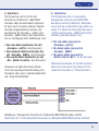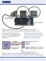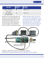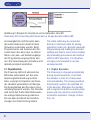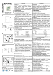
1
eMOTION Powercap micro 8151601 Inhaltsverzeichnis Einleitende Information.................... Warnhinweise.................................. Funktionsumfang............................. Lieferumfang.................................... Anschluss........................................ Digitalbetrieb.................................... Analogbetrieb................................... Technische Daten............................. Garantie, Reparatur, Kundendienst.. Hotline.............................................. Table of contents Introduction..................................... Warning Notes................................. Features........................................... Scope of supply............................... Installation....................................... Digital Operation.............................. Analog Operation............................. Technical specifications................... Warranty, Service, Support.............. Hotline.............................................. 1. Einleitende Information Sehr geehrte Kunden, wir empfehlen die Produktdokumentation und vor allem auch die Warnhinweise vor der Inbetriebnahme gründlich zu lesen und diese zu Beachten. 1. Introduction Dear customer, we strongly recommend that you read this manual and the warning notes thoroughly before installing and operating this product. 2 2 3 4 4 5 8 9 10 10 11 1.1. Warnhinweise • Bauen Sie die Elektronik sorgfältig nach den Anschlussplänen ein. Werden beim Einbau Kabel vertauscht oder Kabel kurzgeschlossen (z.B. Rot + Schwarz), kann dies zur Zerstörung der Elektronik führen. • Ein fehlerhafter Anschluss oder eine unsachgemäße Programmierung des Decoders kann dazu führen das die Lok bei geladenem Powercap unkontrolliert weiterfährt. Die Firma Massoth Elektronik GmbH übernimmt für die dadurch entstandenen Schäden keine Haftung. • Der Powercap darf niemals direkt an die Gleisspannung angeschlossen werden! Dies führt zur Zerstörung und kann Folgeschäden an anderen Komponenten hervorrufen. • Der Powercap ist für Gartenbahnloks mit einer maximalen Stromaufnahme von 1A oder für Soundmodule konzipiert. • Das Modul darf nur für die in der Anleitung genannten Funktionen genutzt werden. Eine anderweitige Verwendung, kann zur Zerstörung führen. • Die Schaltung kann im Betrieb heiß werden! Bitte nicht berühren. • Dieses Produkt ist kein Spielzeug. 1.1. Warning Notes • Please install this product closely following the documented wiring diagrams. A connection error may result in product damage or loss (e.g. mix up of red and black) • A faulty installation or incorrect decoder setting can result in uncontrolled locomotive operation as long as the Powercap is charged. Massoth is not liable for resultant damages. • The Powercap must never be connected directly to the track power! This results in product damage and failure of other components. • The Powercap is especially designed for G scale locomotives or sound modules with a maximum power consumption of 1A. • The Powercap may be used only as stated in this manual. Any other use may lead to destruction. • The circuitry may heat up during operation. Do not touch! • This product is not a toy. 3 1.2. Funktionsumfang Der Powercap micro dient zum Überbrücken von kurzzeitigen Unterbrechungen der Gleisspannung bei Gartenbahnlokomotiven oder zur Pufferung von Geräuschen bei Analogbetrieb im Stillstand. Der Motor und Sonderfunktionen werden während dieser Unterbrechung aus dem Speicher versorgt. Somit können Lokomotiven problemlos über Weichenherzstücke oder Isolierstellen fahren, ohne stehen zu bleiben. Die Dauer der Pufferung beträgt je nach angeschlossener Last, Geschwindigkeit und Ladezustand bis zu 30 Sekunden. Durch eine integrierte Steuerung wird der Puffer immer optimal an das aktuelle Betriebsverhalten angepasst. Bei der Programmierung des Decoders wird der Puffer automatisch komplett abgeschaltet, sofern die Elektronik das unterstützt. Ansonsten kann der Puffer mit dem mitgelieferten Schiebeschalter abgeschaltet werden. Aufgrund der 3-teiligen Bauform lässt sich der Puffer auch in kleinere Gartenbahnfahrzeuge verbauen. 1.2. Features The Powercap micro is used to compensate short-term track power interruptions for G scale locomotives as well as standing sound operation in analog mode. The motor and the locomotive functions are operated with the Powercap during a track power interruption. Locomotives can easily cross switch/ point frogs or insulated track sections (e.g. dirty track sections) without stopping. The buffering time depends on the connected load, driving speed and charge level and lasts up to 30 seconds. The integrated electronic control always adapts the Powercap state to the current operating performance. During programming procedures the Powercap is automatically deactivated if the decoder supports a buffer control connection. Otherwise the Powercap can be operated using the enclosed switch to deactivate the charging. The flexible 3-piece design makes installation and fitting very easy and suitable for smaller G scale locomotives. 1.3. Lieferumfang • Powercap Micro (3-teilig) • Schiebeschalter • Bedienungsanleitung 1.3. Scope of Supply • Powercap micro (three-piece) • slide switch • manual 4 2. Anschluss Der Powercap micro ist für den Anschluss an Massoth „eMOTION“ Decoder oder Soundmodule optimiert. Er kann auch an jeden anderen Digitaldecoder angeschlossen werden, der Anschlüsse für Decoder+ (+22V) und Decoder- (GND) hinter dem Gleichrichter zur Verfügung stellt (Abbildung 1+2): •Das rote Kabel verbinden Sie mit „Decoder+ (+22V)“ des Decoders. •Das schwarze Kabel verbinden Sie mit „Decoder- (GND)“ des Decoders. •Das weiße Kabel verbinden sie mit „BC“ (Buffer-Control)“ des Decoders. Hinweise zum BC-Anschluss finden sie in der jeweiligen Beschreibung des Decoders oder einer Lokbasiselektronik mit „PluG-Schnittstelle“. 2. Installation The Powercap micro is especially designed to connect with eMOTION decoders series by Massoth. Nevertheless it can be connected to any other decoder if it offers the terminals Decoder+ (+22V) and Decoder- (GND) behind the rectifier (see illustration 1+2): •The red cable connects to “Decoder+ (+22V)” •The black cable connects to “Decoder- (GND)” •The white cable connects to “Buffer Control (BC)” on the decoder Detailed information on the BC functionality can be found in the manual of the respective decoder or “PluG-interface”. Abbildung 1: Beispiel für Anschluss an Massoth eMOTION Decoder mit BC Illustration #1: Connecting the Powercap to a Massoth eMOTION Decoder with BC 5 rot an / red to Dec+ schwarz an / black to Dec- weiß an / white to BC Abbildung 2: Beispiel für Anschluss an eMOTION XLS Decoder mit BC Illustration #2: Connecting the Powercap to a eMOTION XLS Decoder with BC Bei älteren Decodern kann „BC“ auf einem Funktionsausgang des Decoders liegen (z.B. A5 beim eMOTION XL). (Abbildung 3) Older decoders may not show the buffer control connection “BC” but can offer it on a function connection (e.g. A5 on the eMOTION XL). (see illustration 3) Abbildung 3: Beispiel für Anschluss an Massoth eMOTION Decoder ohne BC Illustration #3: Connecting the Powercap to a Massoth eMOTION Decoder without BC 6 Anschluss/ Output CV-Wert / CV-value M / L / XL / XXL A5 CV118 = 31 8FL / XLS (alt, ohne BC, old, without BC) A4 CV116 = 31 eMOTION Bei Decodern ohne Steuerausgang „BC“ verbinden sie das weiße Kabel über den beiliegenden Schalter mit dem schwarzen Kabel (GND) (Abbildung 4+5). In diesem fall muss bei der Programmierung des Decoders die Ladefunktion über den Schalter ausgeschaltet werden. Decoders without a buffer control connection can still be equipped with a buffer using the enclosed switch to connect the white cable to the black one (GND) (see illustration 4+5). In this case it is required to switch off the charging function in order to program the decoder. Rot an Dec+ red to Dec+ schwarz an Dec- und Schalter black to Dec- and switch weiss an Schalter white to switch Abbildung 4: Beispiel für Anschluss an LGB 55021 (L55021) Illustration #4: Connecting the Powercap to a LGB 55021 decoder (L55021) 7 Abbildung 5: Beispiel für Anschluss an Fremddecoder ohne BC Illustration #5: Connecting the Powercap to a foreign decoder without BC Im Analogbetrieb (mit Decoder) kann das weiße Kabel auch direkt mit dem Schwarzen verbunden werden. Beim Programmieren und Auslesen des Decoders kann dies dann aber zu Fehlern führen, da Lade- und Entladevorgänge den Programmiervorgang stören können. Die Verwendung des Schalters wird deshalb prinzipiell empfohlen. The white cable may be connected directly to the black cable for analog operation mode only (decoder required). Programming and reading the decoder settings will lead to errors since loading and unloading procedures will interfere with the DCC operation. It is therefore strongly recommended to use the enclosed switch. 2.1 Digitalbetrieb Der Powercap lädt sich während des Betriebes automatisch auf. Bei einer Spannungsunterbrechung auf dem Gleis, versorgt der Speicher den Decoder ebenfalls automatisch mit Energie. Der Analogbetrieb des Decoders muss unbedingt gesperrt werden. Der Decoder wird sonst den Puffer fälschlicherweise als analoge Gleisspannung erkennen. Die Lok kann hierdurch bei Unterbrechungen ihre Fahrtrichtung ändern. 2.1. Digital Operation The Powercap is charged automatically during normal operation. It will feed the decoder in case of a track power loss immediately. The analog operation functionality needs to be switched off in the decoder. Otherwise the decoder will recognize the buffer as analog track power and may result in uncontrolled locomotive operation, change of direction, etc. 8 • Analogbetrieb sperren mit CV 29, Bit 2, Wert 0. Überprüfen Sie die richtige Einstellung bitte anhand Ihrer Decoderanleitung. Bei einigen Decodern kann zusätzlich die maximale Pufferdauer eingestellt werden. Damit kann die Lok z.B. bei „Notaus“ der Zentrale nicht unbegrenzt weiterfahren. 2.2. Analogbetrieb Im Analogbetrieb (mit Lokdecoder) kann über den Puffer das Bremsverhalten bei schlagartigem Spannungsverlust z.B. in einer Trennstelle vor einem rotem Signal optimiert werden. Prüfen sie anhand der Anleitung ihres Decoders, ob und wie diese Funktion unterstützt wird. Das Laden des Puffers erfolgt abhängig von der Höhe der anliegenden Gleisspannung. Je höher die Spannung am Gleis ist, umso stärker wird der Puffer geladen. Der Puffer eignet sich auch zur Wiedergabe von Standgeräuschen bei Soundmodulen, wenn das Fahrzeug stromlos abgestellt wird. Prüfen sie auch hierzu die Anleitung des Soundmoduls zur nötigen Einstellung. • Deactivate analog operation with CV 29, bit 2, value 0. Please check the correct decoder setting corresponding to the respective manual. Some decoders may offer a buffer timer to set the maximum buffering time. This is helpful in case of an emergency stop as otherwise the locomotive will run indefinitely until the buffer is empty. 2.2. Analog Operation In analog operation (decoder required) the Powercap can support a soft braking behavior when there is an abrupt loss of power. Please check your decoders manual if analog braking is supported and how it can be set. The charging behavior of the Powercap depends on the applied track voltage level. The higher the voltage on the track, the stronger and faster the buffer is loaded. The Powercap also supports the operation of a standing sound when the locomotive is shut down. Please check the manual of your decoder or sound module in order to adjust or activate this function. 9 3. Technische Daten • Betriebsspannung 6..24V = (DC) • Maximaler Ladestrom 500mA (bei 22V Gleisspannung) • Eigenverbrauch ca. 10mA • Maximale Ausgangsspannung 18V (bei voller Ladung) • Maximale Stromabgabe 1A • Ladezeit ca. 45 Sekunden (bei vollständiger Entladung, 22V) • konform zu RailCommunity Norm RCN-530 3. Technical specifications • Operating voltage 6...24V DC • Maximum charging current 500mA (at 22V track voltage) • Self Consumption ~ 10mA • Maximum output voltage 18V (at full charge) • Maximum output current 1A • charging time ca. 45 Seconds (at total discharge, 22V) • compliant with RailCommunity standard RCN-530 4. Garantie, Reparatur, Kundendienst MASSOTH gewährt die Fehlerfreiheit dieses Produkts für ein Jahr. Die gesetzlichen Regelungen können in einzelnen Ländern abweichen. Verschleißteile sind von der Garantieleistung ausgeschlossen. Berechtigte Beanstandungen werden kostenlos behoben. Für Reparaturoder Serviceleistungen übergeben Sie das Produkt bitte Ihrem Fachhändler oder senden es direkt an den Hersteller. Unfrei zurückgesendete Sendungen werden nicht angenommen. Eine Kopie des Kaufbelegs wird vorausgesetzt. Für Schäden durch unsachgemäße Behandlung oder Fremdeingriff oder Veränderung des Produkts besteht kein Garantieanspruch. Der Anspruch auf Serviceleistungen erlischt unwiderruflich. 4. Warranty, Service, Support MASSOTH warrants this product against defects in materials and workmanship for one year from the original date of purchase. Other countries might have different legal warranty situations. Normal wear and tear, consumer modifications as well as improper use or installation are not covered. Peripheral component damage is not covered by this warranty. Valid warranty claims will be serviced without charge within the warranty period. For warranty service please return the product to you dealer or send it directly to the manufacturer. Return shipping charges are not covered by MASSOTH. Please include your proof of purchase with the returned goods. 10 Auf unserer Internetseite finden Sie die jeweils aktuellen Broschüren, Produktinformationen, Dokumentation und Softwareprodukte rund um MASSOTHProdukte. Please check our web site for up to date brochures, product information, documentation and software updates. Errors and changes excepted. Irrtümer und Änderungen vorbehalten. 4.1 Hotline Serviceanfragen richten Sie bitte an: 4.1 Hotline For technical support contact: Massoth Elektronik GmbH Mo 14:00-17:30 sowie Do 8:00-12:00 FON +49 (0)6151-35077-38 FAX +49 (0)6151-35077-44 [email protected] Massoth Elektronik GmbH, Germany Mo 2:00-5:30 p.m. Thu 8:00-12:00 a.m. FON +49 (0)6151-3507738 FAX +49 (0)6151-3507744 [email protected] Dieses Produkt entspricht den CE Konformitätsrichtlinien für elektrische Kleingeräte in der aktuellen Fassung. This unit conforms to the CE Standards RoHS COMPLIANT 032377o Dieses Produkt ist nach den aktuellen EG Richtlinien umgangssprachlich „bleifrei“ hergestellt und damit RoHS-konform. This unit is manufactured according to the latest EG Standards for lead free manufacturing conforming to RoHS Standard. Entsorgen Sie das Produkt nicht im Hausmüll. Nutzen Sie bitte den dafür vorgesehenen Elektroschrott. Please dispose of according to your State regulations. Werfen Sie das Produkt nicht in offenes Feuer oder durch Hitze entflammbare Brennstoffe. Do not dispose of in open fire. 11 Massoth Elektronik GmbH Frankensteiner Str. 28 · D-64342 Seeheim · Germany FON: +49 (0)6151-35077-0 · FAX: +49 (0)6151-35077-44 eMail: [email protected] · www.massoth.de 8151601_06_2012_ML (991058) QUALITY MADE IN GERMANY