1
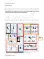
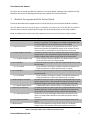
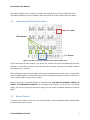
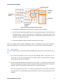
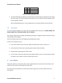
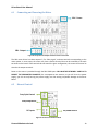
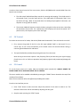
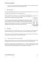
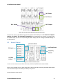
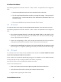
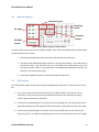
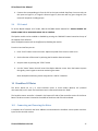
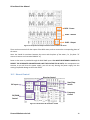
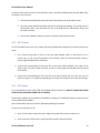
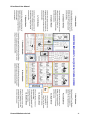
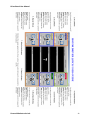
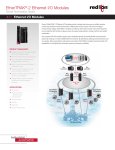
Personal Mechatronics Lab Driver Board User Manual ©2012 by M.R. Emami Driver Board User Manual Table of Contents General Notes ............................................................................................................................................... 3 1 Modular Arrangement of the Driver Board .......................................................................................... 4 2 Powering the Board .............................................................................................................................. 5 3 Computer Interface............................................................................................................................... 5 4 Driver Board Software .......................................................................................................................... 5 5 Unipolar Stepper Motor........................................................................................................................ 6 5.1 Connecting and Powering the Motor ........................................................................................... 7 5.2 Manual Control ............................................................................................................................. 7 5.3 PIC Control .................................................................................................................................... 8 5.4 PC Control ..................................................................................................................................... 9 6 Servo Motor .......................................................................................................................................... 9 6.1 Connecting and Powering the Motor ......................................................................................... 10 6.2 Manual Control ........................................................................................................................... 10 6.3 PIC Control .................................................................................................................................. 11 6.4 PC Control ................................................................................................................................... 11 7 Mode Selector ..................................................................................................................................... 12 8 DC Motor............................................................................................................................................. 12 8.1 Connecting and Powering the Motor ......................................................................................... 12 8.2 Manual Control ........................................................................................................................... 13 8.3 PIC Control .................................................................................................................................. 14 8.4 PC Control ................................................................................................................................... 14 9 Bipolar Stepper Motor ........................................................................................................................ 15 9.1 Connecting and Powering the Motor ......................................................................................... 15 9.2 Manual Control ........................................................................................................................... 16 9.3 PIC Control .................................................................................................................................. 16 9.4 PC Control ................................................................................................................................... 17 10 Brushless DC Motor ........................................................................................................................ 17 10.1 Connecting and Powering the Motor ......................................................................................... 17 10.2 Manual Control ........................................................................................................................... 18 10.3 PIC Control .................................................................................................................................. 19 10.4 PC Control ................................................................................................................................... 19 Personal Mechatronics Lab 2 Driver Board User Manual General Notes The Driver Board V 3.0 has been designed with the user in mind. It is an educational printed circuit board that offers a complete method to test and understand motor drivers. The Driver Board is capable of running 2 DC motors, 1 unipolar stepper motor, 1 bipolar stepper motor, 1 servo motor and 1 brushless DC motor and it provides the user the option of running the motors either manually, using an external microcontroller or using the computer application software. The Driver Board is capable of running the following motor configurations simultaneously: 1. 2 DC Motors, 1 Unipolar Stepper Motor, 1 Servo Motor and 1 Brushless Motor OR 2. 1 Bipolar Motor, 1 Unipolar Stepper Motor, 1 Servo Motor and 1 Brushless Motor Throughout this User Manual a logic of 1 or high logic refers to +5 Volts, and a logic of 0 or a low logic refers to a ground (0 Volts) signal. Also, the maximum current that any motor can draw is 5 amperes. 1 2 5 4 3 4a 5a 7a 9 6a 6 8 7 3a Figure 1. An overview of the modules of the Driver Board Personal Mechatronics Lab 3 Driver Board User Manual The above picture shows the different modules on the Driver Board. Although these modules are fully labelled on the board, the following table shows each module with a brief description. 1 Modular Arrangement of the Driver Board The Driver Board has been arranged to be user friendly and each circuit have been divided in modules. The new Driver Board has two main parts: a controller and a driver part. The left side of the board contains all the controller modules while the right side of the board contains all the driver modules. Power and Output terminals have also been separated in the layout of the board to avoid confusion. Module 1 – Power 2 – Computer Interface 3 – Unipolar Stepper Controller 3a – Unipolar Stepper Driver 4 – DC 1 Controller 4a – DC 1 Driver 5 – DC 2 Controller 5a – DC 2 Driver 6 – Bipolar Stepper Controller 6a – Bipolar Stepper Driver 7 – Brushless DC Controller 7a – Brushless DC Driver 8 – Servo Motor Controller 9 – Mode Selector Description Provides the necessary power for the controller side of the board. It has a 2.1 mm jack for a 12 V adapter, the voltage is regulated to +5V. A 1.25 A protection fuse can also be found in this module Provides a USB connector for communication with the PC. The onboard microcontroller (PIC18F4550) resides on this module. The PIC microcontroller is responsible for the PC-Board communication Provides the tools to control the speed and direction of the unipolar stepper motor. It also provides the required terminals to drive the unipolar stepper motor when using an external microcontroller. Set of transistors and LED indicators that allow the user to verify which coil of the motor is being energized Provides the necessary tools to control the speed and direction of the first DC motor. Set of transistors forming an H-bridge. Provides LED indicators to shows the direction in which the first motor is running Provides the necessary tools to control the speed and direction of the second DC motor. Set of transistors forming an H-bridge. Provides LED indicators to shows the direction in which the second motor is running Provides the necessary tools to control the speed and direction of the bipolar stepper motor. It also provides the required terminals to drive the bipolar stepper motor when using an external microcontroller. Combination of DC 1 and DC 2 drivers, connected by jumper J1 Provides the necessary tools to control the speed and direction of the brushless DC motor. It also provides the required terminals to drive the brushless DC motor when using an external microcontroller. Combination of three half bridges connected to the phases of the motor. It provides LED indicators to show the two phases that are always on. Provides the necessary tools to control the movement of the servo motor. Switch to select between running the DC motors or the bipolar stepper motor. LED indicators show what mode the board is on. Table 1. A brief description of the modules of the Driver Board Personal Mechatronics Lab 4 Driver Board User Manual 2 Powering the Board The Driver Board can be powered in two ways: using the POWER module or through the USB connector. The Power Module: The board can be powered using the 12 V. power Figure 2. The Power module adapter. The voltage is after regulated to +5 V. Most of the LEDs on the board will turn ON once power is applied. Note: Applying power to the board ONLY powers the controller side of the board. The USB Connector: The power module can be bypassed by using the USB connection. An LED indicator in the Computer Interface module will light up as soon as the connection is established. Figure 3. The USB connector The Power switch turns the Driver Board ON or OFF no matter which method is used to power the board. 3 Computer Interface The driver board is capable of communicating with a PC by using the USB port. The motors can be monitored and controlled from a PC. To use the computer interface: Connect the USB cable to the board Install and launch the application on the PC Turn the board ON Figure 4. The Computer Interface module To use the Computer Interface module, you need to install the Driver Board Software. 4 Driver Board Software The Driver Board software, called Motor Controller, is a Windows-based interface that allows communication between the PC and the Driver Board. Personal Mechatronics Lab 5 Driver Board User Manual Once the software is installed and launched, the main will window will be displayed. All the modules of the window will be disabled as long as the USB cable is unplugged. Also, the STATUS of the board will show “Not Connected” and the red indicator will be on. Figure 5. The main window of the interface When the board is connected through USB to the PC, the board STATUS will be “Connected” and the green indicator will light up. As soon as the board is connected, the monitor windows located in the middle of the window will display the real time information from the motors. Also, all the modules (excluding the bipolar module) will become enabled. NOTE: When using the driver board software to run any motors, power the board using the DC jack. The USB connection will be mainly used for communicating with the PC 5 Unipolar Stepper Motor The driver board can run the unipolar stepper motor in three modes: Manual, PIC (external microcontroller) or PC mode. The unipolar stepper motor is referenced in board as “UP”. Personal Mechatronics Lab 6 Driver Board User Manual The unipolar stepper motor controller is located in the top right corner of the controller side of the Driver Board. The driver section is located in the lower section of the driver side of the Driver Board. 5.1 Connecting and Powering the Motor UP - Power LED Indicators UP - Output Figure 6. The power and output terminals of the unipolar stepper motor The UP motor driver has five outputs: C, for ‘Centre Tap’, and four terminals corresponding to the motor windings. In some cases, the motor may have more than one center tap lead; all such leads should be connected to the ‘C’ terminal. The remaining terminals, for the windings, are activated sequentially by the motor driver as indicated by their corresponding LED’s, and should be connected to the appropriate leads on the motor. Failure to do so will cause the motor to stall and to overheat. Power to the motor is provided through the UP-PWR inputs. YOU MUST BE EXTREMELY CAREFUL TO RESPECT THE DESIGNATED POLARITIES, the consequences are extreme, as you will short the power supply; you risk not only burning the power supply, but also causing irreparable damage to the Driver Board. 5.2 Manual Control In order to have manual control over the Unipolar Stepper, slide the PIC/MAN switch towards MAN. Once the board is set to manual: Personal Mechatronics Lab 7 Driver Board User Manual Direction Control PIC/MAN Control Start/Stop Switch PIC Inputs Frequency Control Figure 7. The Unipolar Stepper Controller module 1. The slide switch labelled Direction will control the direction of the UP Motor. 2. The slide switch labelled Start/Stop controls the starting and stopping. If the slide switch is slid towards “Start”, then the motor will run; if the slide switch is slid towards “Stop”, then the motor will stop. (Note: in stop mode, there is a holding torque applied to the motor, not all power is cut-off from the motor) 3. The trimmer labelled Frequency controls the speed of the UP motor. Note: The unipolar module requires initialization which is automatically done when the board is powered. If the module is not working correctly make sure to reset the board to initialize the module. 5.3 PIC Control To set the Unipolar Stepper to PIC mode, slide the PIC/MAN switch towards PIC. Once the board is set to PIC: 1. First, connect the ground of the PIC to the PIC input labelled “GND” on the board. This is a crucial step, as the correct functionality of the board cannot be ensured without having a common ground between PIC and Board. 2. PIC inputs S0 and S1 determine the direction of the UP motor. It is important to never ground both inputs. Setting S0 to a logical 1 and S1 to a logical 0 will provide one rotation. Setting S1 to a logical 1 and S0 to a logical 0 will provide rotation in the opposite direction. Note: if at any point the UP motor is no longer functioning and the circuit seems to be acting erratically, then it is recommended that you reinitialize the circuit by briefly setting S0 and S1 to a logical 1. Personal Mechatronics Lab 8 Driver Board User Manual S0 0 1 1 S1 1 0 1 Output Direction 1 Direction 2 Initialization Table 2. The S0/S1 combination result 3. The input labelled CLK provides the clock that will run the shift register and determine the speed of the UP motor. The minimum width of clear pulse is 20 ns, and the maximum frequency that can be supplied is 25 MHz. NOTE: Avoid high frequencies. Very low frequencies in the range of 100 Hz will work just fine. 5.4 PC Control To set the Unipolar Stepper to PC mode, slide the PIC/MAN switch towards PIC. ALWAYS POWER THE BOARD USING THE DC JACK WHEN USING THE PC CONTROL. The Unipolar module can be enabled or disabled by pressing the “UNIPOLAR” button located at the top of the module of the software. Note: The Unipolar monitor will not be affected by disabling the module. From the User Interface you can: 1. Press “PLAY” button to start the motor. Adjust the speed of the motor to make it run 2. Set the direction of the motor by selecting the Forward or Reverse buttons 3. Stop the motor by pressing the “STOP” button 4. Use the “Pause” button that will control the Unipolar Monitor screen. Press the button to pause the signals, press it again to continue monitoring the motor 6 Servo Motor The driver board can run the servo motor in three modes: Manual, PIC (external microcontroller) or PC mode. The servo motor is referenced in board as “SRV”. The servo motor controller/driver is located in the bottom right corner of the controller side of the Driver Board. Personal Mechatronics Lab 9 Driver Board User Manual 6.1 Connecting and Powering the Motor SRV - Power SRV - Output Figure 8. The power and output terminals of the servo motor The SRV motor driver has three outputs: P, for ‘Pulse signal’, and two terminals corresponding to the motor power. In some cases, the motor may have a female terminal that can be matched to the male terminals on the board. If the terminals do not match the given configuration, the motor will have to be wired to the output terminals. Power to the motor is provided through the SRV-PWR inputs. YOU MUST BE EXTREMELY CAREFUL TO RESPECT THE DESIGNATED POLARITIES, the consequences are extreme, as you will short the power supply; you risk not only burning the power supply, but also causing irreparable damage to the Driver Board. 6.2 Manual Control Duty Cycle Control Start/Stop switch PIC Inputs PIC/MAN Control Figure 9. The Servo Controller module Personal Mechatronics Lab 10 Driver Board User Manual In order to have manual control of the servo motor, slide the PIC/MAN switch towards MAN. Once the board is set to manual: 1. The slide switch labelled Start/Stop controls the starting and stopping. If the slide switch is slid towards “Start”, then the motor will run; if the slide switch is slid towards “Stop”, then the motor will stop. (Note: in stop mode there is a holding torque applied to the motor, not all power is cut-off from the motor) 2. The trimmer labelled Frequency controls the duty cycle given to the servo motor, controlling the movement of the motor. For a speed servo, this frequency will control the speed. For a position servo, this frequency will control the angle. 6.3 PIC Control To set the servo motor to PIC mode, slide the PIC/MAN switch towards PIC. Once the board is set to PIC: 1. First, connect the ground of the PIC to the PIC input labelled “GND” on the board. This is a crucial step, as the correct functionality of the board cannot be ensured without having a common ground between PIC and Board. 2. The input labelled CLK provides the pulse signal that will run the motor. Note: Driving a servo motor requires a low frequency (50 Hz) and low duty cycle signal ranging from 0.9 ms to 2.1 ms. Failure to provide a low frequency signal could permanently damage the motor. 6.4 PC Control To set the Servo motor to PC mode, slide the PIC/MAN switch towards PIC. ALWAYS POWER THE BOARD USING THE DC JACK WHEN USING THE PC CONTROL. The servo module can be enabled or disabled by pressing the “SERVO” button located at the top of the module of the software. Note: The servo monitor will not be affected by disabling the module. From the User Interface you can: 1. Press “PLAY” button to start the motor. Adjust the position of the motor to make it run. The direction of the motor will be controlled by adjusting the duty cycle 2. Stop the motor pressing the “STOP” button Personal Mechatronics Lab 11 Driver Board User Manual 3. Use the “Pause” button that will control the Servo Monitor screen. Press the button to pause the signals, press it again to continue monitoring the motor 7 Mode Selector The Driver Board CANNOT simultaneously run the DC motors and a Bipolar Stepper motor. The mode Selector determines which type of motor the board is set to run. Within the Mode Selector module there are two indicative LEDs that display which mode the board is in. If the LED next to DC is ON, then the motor is in DC MODE. If the LED next to BP is ON, then the board is in Bipolar MODE. It is also crucial to change the position of the Mode jumper. If the board is set to BP mode it is ESSENTIAL to also PLACE THE MODE JUMPER on the BP side of the headers. The same is true for DC mode, if the board is in DC mode, the jumper SHOULD be placed on the DC header (Note: If the jumper is in the wrong position, you do not risk damaging the board; however, the board will not function correctly). Figure 10. The Mode Selector module 8 DC Motor The driver board can run the two DC motors each in any of the following three modes: Manual, PIC (external microcontroller) or PC mode. The DC motors are referenced in board as “DC1” and “DC2”. The DC motor controller is located below in power and computer interface modules. The driver section is located in the top section of the driver side of the Driver Board. 8.1 Connecting and Powering the Motor Simply connect both leads of your DC motor to DC1-OUT (polarity irrelevant) and similarly for your second DC motor: connect it to DC2-OUT (only in the case that you wish to run two DC motors). The drivers for each DC motor are fully independent, thus it is necessary to provided power to both power inputs (DC1-PWR and DC2-PWR) if both motors are going to be run. Different power sources can be used for each motor, or the same power source can be used to run both motors. Personal Mechatronics Lab 12 Driver Board User Manual DC1- Power DC2- Power DC1- Output DC2- Output Figure 11. The power and output terminals of the DC motors Power to the motors is provided through the DC1-PWR and DC2-PWR inputs. YOU MUST BE EXTREMELY CAREFUL TO RESPECT THE DESIGNATED POLARITIES, the consequences are extreme, as you will short the power supply; you risk not only burning the power supply, but also causing irreparable damage to the Driver Board. 8.2 Manual Control Direction Switch Start/Stop Switch PIC Inputs Frequency Control PIC/Man Control Figure 12. The DC Controller module In order to have manual control of the DC motors, slide the PIC/MAN switch towards MAN. Note: It is not possible to run 1 motor using the PIC and the second motor using the Board. Both boards must simultaneously be controlled by the board, or by the PIC. Once the board is set to manual: Personal Mechatronics Lab 13 Driver Board User Manual (The following explanations will make reference to DC1, however all explanations are analogous for DC2) 1. The slide switch labelled Direction will control the direction of the DC motor. 2. The slide switch labelled Start/Stop controls the starting and stopping. If the slide switch is slid towards “Start”, then the motor will run; if the slide switch is slid towards “Stop”, then the motor will stop. 3. The trimmer labelled Duty Cycle controls the speed of the DC motor. 8.3 PIC Control To set the DC motors to PIC mode, slide the PIC/MAN switch towards PIC. Once the board is set to PIC: (The following explanations will make reference to DC1, however all explanations are analogous for DC2) 1. First, connect the ground of the PIC to the PIC input labelled “GND” on the board. This is a crucial step, as the correct functionality of the board cannot be ensured without having a common ground between PIC and Board. 2. Connect the corresponding pin from the PIC to the input marked DC1 CLK. This input will be a clock signal that will determine the speed of the DC motor based on the duty cycle. 3. Connect the corresponding pin from the PIC to the input marked DC1 DIR. You must only set this input to a logical 1, or a logical 0. Depending on the input, the rotation of the motor will change. 8.4 PC Control To set the DC motors to PC mode, slide the PIC/MAN switch towards PIC. ALWAYS POWER THE BOARD USING THE DC JACK WHEN USING THE PC CONTROL. The DC modules can be enabled or disabled by pressing the “DC 1 MOTOR” and “DC 2 MOTOR” buttons located at the top of the DC 1 and DC 2modules of the software, respectively. Note: The DC monitors will not be affected by disabling the module. From the User Interface you can: 1. Press “PLAY” button to start the motor. Adjust the speed of the motor to make it run. 2. Set the direction of the motor by selecting the Forward or Reverse buttons 3. Stop the motor by pressing the “STOP” button Personal Mechatronics Lab 14 Driver Board User Manual 4. Use the “Pause” button that will control the DC Monitor screen. Press the button to pause the signals, press it again to continue monitoring the motor 9 Bipolar Stepper Motor The driver board can run the bipolar stepper motor in three modes: Manual, PIC (external microcontroller) or PC mode. The bipolar stepper motor is referenced in board as “BP”. Do not forget to set the Mode Selector to BP in order to use this motor. The bipolar stepper motor controller is located in the middle left side of the controller section of the Driver Board. The driver section is located in the top part of the driver side of the Driver Board. 9.1 Connecting and Powering the Motor BP - Power BP - Output Figure 13. The power and output terminals of the bipolar stepper motor The DC motor outputs become the BP motor outputs in BP mode. There are four terminals corresponding to the motor windings. The terminals are activated sequentially by the motor driver as indicated by their corresponding LED’s, and should be connected to the appropriate leads on the motor. Failure to do so will cause the motor to stall and to overheat. Power to the motor is provided through the DC1-PWR or DC2-PWR inputs. (It is irrelevant which input you power, DC1-PWR, DC2-PWR or even both together, it all amounts to the same thing). However, YOU MUST BE EXTREMELY CAREFUL TO RESPECT THE DESIGNATED POLARITIES, the consequences are extreme, as you will short the power supply; you risk not only burning the power supply, but also causing irreparable damage to the Driver Board. Personal Mechatronics Lab 15 Driver Board User Manual 9.2 Manual Control Direction Control Start/Stop Switch PIC Inputs Frequency Control PIC/MAN Control Figure 14. The Bipolar Stepper Controller module In order to have manual control of the Bipolar Stepper motor, slide the PIC/MAN switch towards MAN. Once the board is set to manual: 1. The slide switch labelled Direction will control the direction of the BP motor. 2. The slide switch labelled Start/Stop controls the starting and stopping. If the slide switch is slid towards “Start”, then the motor will run; if the slide switch is slid towards “Stop” then the motor will stop. (Note: in stop mode there is a holding torque applied to the motor, not all power is cut-off from the motor) 3. The trimmer labelled Frequency controls the speed of the BP motor. 9.3 PIC Control To set the Bipolar Stepper to PIC mode, slide the PIC/MAN switch towards PIC. Once the board is set to PIC: 1. First, connect the ground of the PIC to the PIC input labelled “GND” on the board. This is a crucial step, as the correct functionality of the board cannot be ensured without having a common ground between PIC and Board. 2. Connect the corresponding pin from the PIC to the input marked CLK. This input will be a clock signal that will determine the speed of the BP motor based on the frequency of the clock signal. 3. Connect the corresponding pin from the PIC to the input marked DIR. You must only set this input to a logical 1, or a logical 0. Depending on the input, the rotation of the motor will change. Personal Mechatronics Lab 16 Driver Board User Manual 4. Connect the corresponding pin from the PIC to the input marked Start/Stop. You must only set this input to a logical 1, or a logical 0. Given a logical 1, the motor will run; given a logical 0, the motor will stop with a holding torque. 9.4 PC Control To set the Bipolar Stepper to PC mode, slide the PIC/MAN switch towards PIC. ALWAYS POWER THE BOARD USING THE DC JACK WHEN USING THE PC CONTROL. The Bipolar module can be enabled or disabled by pressing the “BIPOLAR” button located at the top of the module of the software. Note: The Bipolar monitor will not be affected by disabling the module. From the User Interface you can: 1. Press “PLAY” button to start the motor. Adjust the speed of the motor to make it run. 2. Set the direction of the motor by selecting the Forward or Reverse buttons 3. Stop the motor by pressing the “STOP” button 4. Use the “Pause” button that will control the Bipolar Monitor screen. Press the button to pause the signals, press it again to continue monitoring the motor. Note: the bipolar monitoring is done using the DC 1 and DC 2 monitors. 10 Brushless DC Motor The driver board can run a 5 Volts brushless motor in three modes: Manual, PIC (external microcontroller) or PC mode. The brushless motor is referenced in board as “BLDC”. The brushless motor controller is located in the bottom left side of the controller section of the Driver Board. The driver section is located in the middle of the driver side of the Driver Board. 10.1 Connecting and Powering the Motor A complete set of terminals has been added to accommodate the brushless sensors power and their inputs to the controller section. Personal Mechatronics Lab 17 Driver Board User Manual BLDC - Power BLDC - Sensors BLDC - Output Figure 15. The power and output terminals of the brushless DC motor There are three terminals for the output of the BLDC motor, each to connect the corresponding phase of the motor. Note: You should be consistent between the sensor and the phase of the motor. (i.e. for phase “A” connect its sensor to the terminal labelled “a”) Power to the motor is provided through the BLDC-PWR inputs. YOU MUST BE EXTREMELY CAREFUL TO RESPECT THE DESIGNATED POLARITIES AND LIMIT THE VOLTAGE TO 18 VOLTS, the consequences are extreme, as you will short the power supply; you risk not only burning the power supply, but also causing irreparable damage to the Driver Board. 10.2 Manual Control Direction Control Start/Stop Switch PIC Inputs Frequency Control PIC/MAN Control Figure 16. The Brushless DC Controller module Personal Mechatronics Lab 18 Driver Board User Manual In order to have manual control of the Brushless motor, slide the PIC/MAN switch towards MAN. Once the board is set to manual: 1. The slide switch labelled Direction will control the direction of the brushless motor. 2. The slide switch labelled Start/Stop controls the starting and stopping. If the slide switch is slid towards “Start”, then the motor will run; if the slide switch is slid towards “Stop” then the motor will stop. 3. The trimmer labelled Frequency controls the speed of the brushless motor. 10.3 PIC Control To set the Brushless DC motor to PIC mode, slide the PIC/MAN switch towards PIC. Once the board is set to PIC: 1. First, connect the ground of the PIC to the PIC input labelled “GND” on the board. This is a crucial step, as the correct functionality of the board cannot be ensured without having a common ground between PIC and Board. 2. Connect the corresponding pin from the PIC to the input marked ON/OFF. This input can be either a logic 1 for ON, or logic 0 for OFF, as well as a clock signal that will determine the speed of the motor. 3. Connect the corresponding pin from the PIC to the input marked DIR. You must only set this input to a logical 1, or a logical 0. Depending on the input, the rotation of the motor will change. 10.4 PC Control To set the Brushless to PC mode, slide the PIC/MAN switch towards PIC. ALWAYS POWER THE BOARD USING THE DC JACK WHEN USING THE PC CONTROL. The Brushless module can be enabled or disabled by pressing the “UNIPOLAR” button located at the top of the module of the software. Note: The Brushless monitor will not be affected by disabling the module. From the User Interface you can: 1. Press “PLAY” button to start the motor. Adjust the speed of the motor to make it run. 2. Set the direction of the motor by selecting the Forward or Reverse buttons Personal Mechatronics Lab 19 Driver Board User Manual 3. Stop the motor by pressing the “STOP” button 4. Use the “Pause” button that will control the Brushless Monitor screen. Press the button to pause the signals, press it again to continue monitoring the motor Personal Mechatronics Lab 20 Driver Board User Manual Personal Mechatronics Lab 21 Driver Board User Manual Personal Mechatronics Lab 22