1
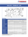
NuFloTM Orifice Fittings and Equipment User Manual Dual Chamber Orifice Fittings Single Chamber Orifice Fittings Orifice Flange Unions Orifice Plates Orifice Meter Runs Sold as North Star Flow Products in Canada Manual No. 25165001, Rev. A © 2004 NuFlo Technologies, Inc. All information contained in this publication is confidential and proprietary property of NuFlo Technologies, Inc. Any reproduction or use of these instructions, drawings, or photographs without the express written permission of an officer of NuFlo Technologies, Inc. is forbidden. All Rights Reserved. Printed in the United States of America. Manual No. 25165001, Rev. A November 2004 Table of Contents Dual Chamber Orifice Fittings Features and Specifications ............................................................................................................ 1 Installation, Maintenance, and Operation ........................................................................................ 3 Composite Drawing, 2” and 3” with Internal Ball-Stop ..................................................................... 4 Composite Drawing, 4” with Internal Ball-Stop ................................................................................ 5 Parts List, 2”, 3” and 4” with Internal Ball-Stop ................................................................................ 6 Composite Drawing, 6” with Internal Ball-Stop ................................................................................ 8 Parts List, 6” with Internal Ball-Stop ................................................................................................ 9 Dimensional Data, 2”and 3” Orifice Fittings ................................................................................... 11 Dimensional Data, 4” Orifice Fittings ............................................................................................. 12 Dimensional Data, 6” Orifice Fittings ............................................................................................. 13 Redress Kits and Recommended Spare Parts .............................................................................. 18 Single Chamber Orifice Fittings Features and Specifications .......................................................................................................... 19 Installation, Maintenance, and Operation ...................................................................................... 19 Composite Drawing, 2”, 3” and 4”.................................................................................................. 21 Parts List, 2”, 3” and 4” .................................................................................................................. 22 Dimensional Data, 2”, 3” and 4”..................................................................................................... 23 Meter Runs Specifications ................................................................................................................................ 27 Orifice Flange Unions .................................................................................................................... 29 Paddle Type Orifice Plates ............................................................................................................ 29 Orifice Plate Assembly................................................................................................................... 30 Straightening Vanes ...................................................................................................................... 31 AGA/API Meter Run Lengths......................................................................................................... 32 Data Requirements for Orifice Bore Calculations .......................................................................... 33 Meter Run Ordering Forms............................................................................................................ 34 Materials Lists................................................................................................................................ 37 i ii Model 4055 Dual Chamber Orifice Fittings NuFlo Model 4055 Dual Chamber Orifice Fittings are compact, streamlined and rugged featuring a simple and rapid method for changing or inspecting orifice plates under pressure. The orifice fittings feature a ball-type construction for opening and closing “without” a complicated gear mechanism. The unique construction incorporating a ball closure with spring-loaded, self-lubricating, Moly-filled Teflon® floating seals eliminates any need for periodic lubrication. All NuFlo dual chamber orifice fittings are manufactured in accordance with ANSI and ATSM standards and available in 2”, 3”, 4” and 6” sizes. Features • • • • • Compact construction Rapid method for changing orifice plates under pressure Self-lubricating Moly-filled Teflon® seals (periodic lubrication not required) Orifice plate O-ring seal provides positive seal around orifice plate Positive orifice plate alignment assured with closure of chamber lid and internal ball stop Standard Specifications Meter Connections: All NuFlo orifice fittings are provided with two sets of flange taps located 1” on each side of the orifice plate. Flange tap meter connections are 1/2” NPT, internal tap hole sizes follow latest AGA/API recommendations. Internal edges of tap holes are free from burrs and slightly rounded. Two types of NuFlo orifice fittings are available: • Flanged Type, either raised face or ring joint • Flangeweld Type, having a weldneck inlet and a flanged outlet When Ordering, Specify: • Quantity • Assembly part number • Type of dual chamber orifice fitting (flanged, flangeweld) • Service (sweet, (H2S) sour) • Flange rating • Flange type (raised face, ring type joint) • Pipe schedule • Orifice plate bore size(s) ORIFICE FITTING SIZES 2” 3” 4” 6” ASSEMBLY PART NUMBER 40552 40553 40554 40556 ANSI FLANGE PRESSURE RATINGS 150 THROUGH 1500 150 THROUGH 1500 150 THROUGH 1500 150 THROUGH 600 INTERNAL DIAMETERS SCH 40 THROUGH SCH 160 SCH 40 THROUGH SCH 160 SCH 40 THROUGH SCH 160 SCH 40 THROUGH SCH 80 1 2” Model 40552 Optional Bleed-Off Extension Dual chamber orifice fitting, flanged type Cut-away, dual chamber orifice fitting, flangeweld type (2, 3 and 4 in.) 2 Dual chamber orifice fitting, flangeweld type (6 in.) Installation and Maintenance It is recommended that the NuFlo Dual Chamber Orifice fitting be placed in the line with the two 1/2” NPT flange taps and instruction plate facing upward. The flow arrow cast on the body must correspond with flow direction of line. The orifice fitting is shipped with an orifice plate installed in operating position. It is suggested that the orifice plate be removed before flushing or purging the flow line. The spring-loaded, self-lubricated Moly-filled Teflon® ball seals eliminate any need for periodic lubrication. Grease is not required for sealing. Operating Instructions Removing an Orifice Plate Replacing an Orifice Plate 1. Close main orifice fitting. This rotates the orifice plate out of operation and places the bypass section into the orifice fitting bore. 2. Insure “EQUALIZER” valve is closed. 3. Open the “BLEED” valve. This vents the pressure around the orifice plate and chamber lid. 4. Open the chamber lid by loosening the hinge bolt cap nuts and removing the two top cap nuts. This will allow the chamber lid to open freely. 5. Remove orifice plate and retainer with the wrench supplied with unit. 1. Place orifice plate and retainer into the ball slot with “OUTLET” on plate holder facing “OUTLET” stamped on body casting. 2. Close chamber lid and tighten the four cap nuts. 3. Close “BLEED” valve. 4. Open “EQUALIZER” valve to equalize ball seal pressure. 5. Open main orifice fitting. This places orifice plate into operation and removes bypass section from the bore. 6. Close “EQUALIZER” valve. 3 2” and 3” MODEL 4055 DUAL CHAMBER ORIFICE FITTINGS WITH INTERNAL BALL-STOP CL ' B' 'C' 'D' 41 CL 6 47 48 47 'A' 'A' E OS CL OVE E M RE RIFIC O CL CL OP OP EN ER AT E NS 40 CL CL CL 45 46 ' D' 'C' CL 'B' 42 SECTION 'C-C' 40 4 5 1 TOP VIEW 22 CL 2 3 3 CL 39 CL CL 37 7 9 13 33 37 SECTION 'D-D' 12 14 32 8 31 CL CL 15 SECTION 'B-B' ' 17 27 38 38 26 NS 18 43 CL CL FLOW FLOW 24 44 28 25 19 SECTION 'A–A' 4 35 36 21 34 29 22 23 20 30 4” MODEL 4055 DUAL CHAMBER ORIFICE FITTING WITH INTERNAL BALL-STOP (SEE PAGE 8 FOR 6” DUAL CHAMBER FITTING DRAWING) CL ' B' 'C' 41 CL 'A' 'A' VE O E Z EM IC R RIF O 'D' CL CL NS N ATE PE R O PE O 40 CL 45 46 ' D' 'C' 6 CL 'B' 4 42 5 SECTION 'C-C' 40 1 TOP VIEW 2 3 CL 22 3 CL 37 33 13 9 6 8 32 31 12 14 11 10 CL 15 16 17 SECTION 'B-B' 37 SECTION 'D-D' 39 ' 27 38 38 26 NS 18 43 CL 44 FLOW FLOW 24 28 25 SECTION 'A-A' 19 35 36 21 34 29 22 23 20 30 5 PARTS LIST 2”, 3” and 4” MODEL 4055 DUAL CHAMBER ORIFICE FITTINGS WITH INTERNAL BALL-STOP ITEM 6 DESCRIPTION QTY. ASSY. NO. 40552 (2”) PART NO. ASSY. NO. 40553 (3”) PART NO. ASSY. NO. 40554 (4”) PART NO. 1 SPRING 1 40701-053-04000 40701-053-04000 40701-053-04000 2 0.250 316 S.S. BALL 1 01001-030-04300 01001-030-04300 01001-030-04300 3 BLEED VALVE ASSEMBLY 2 40701-J00-06000 40701-J00-06000 40701-J00-06000 4 INSTRUCTION PLATE 1 40701-009-04000 40701-009-04000 40701-009-04000 5 DRIVE SCREW #4 - 1/4” TYPE U 4 NCN NCN NCN 6 SET SCREW (ALLEN HEAD) 2 NA 5/16” - 18 TPI X 1/4” 3/8” - 16 TPI X 1/2” 7 ROLL PIN 1 1/8” X 7/8” 8 BALL STOP 1 40552-119-04000 40553-130-04000 40554-138-04000 9 BALL STEM 1 40552-046-04000 40553-048-04000 40554-042-04000 10 SPUR GEAR 40704-004-04000 11 SPUR GEAR STEM 1 12 O-RING STEM RETAINER 1 40700-060-06000 40713-035-06000 40704-046-04000 40714-046-06000 13 STEM RETAINER 1 40552-027-04000 40703-016-04000 40704-033-04000 14 STEM RING 1 40701-014-04000 40703-018-04000 40704-034-04000 15 O-RING STEM RETAINER 2 40700-061-06000 40714-047-06000 40714-048-06000 16 STEM LOCK 1 17 O-RING STEM RETAINER 1 40700-059-06000 40713-036-06000 40714-047-06000 18 ORIFICE FITTING WRENCH 1 40701-075-00000 40703-045-00000 40704-031-00000 19 WAVE SPRING (STANDARD) WAVE SPRING (H2S) SOUR 5 40700-009-03000 40700-020-06000 40703-088-03000 40703-093-06000 40704-082-04000 40704-087-06000 20 DOVETAIL RING 1 40712-001-04000 40713-006-04000 40714-010-04000 21 STANDARD ORIFICE PLATE 316 S.S 1 40552-052-00000 40553-055-00000 40554-049-00000 22 STANDARD ORIFICE PLATE RETAINER ORIFICE PLATE RETAINER ORIFICE PLATE RETAINER (TEFLON) 1 40552-062-04000 40552-069-04000 40553-062-04000 40553-065-04000 40554-063-04000 40554-065-04000 23 O-RING PLATE RETAINER O-RING (TEFLON) PLATE RETAINER 1 40700-005-06000 40552-059-06000 40702-025-06000 40553-060-06000 40714-052-06000 40554-059-06000 24 ORIFICE FITTING BODY 150# - 600# RATING SCH - 40 150# - 600# RATING SCH - 80 150# - 600# RATING SCH - 160 900 - 1500# RATING SCH - 80 900 - 1500# RATING SCH -160 1 40552-023-04000 40552-024-04000 40552-025-04000 40552-024-04000 40552-025-04000 40553-023-04000 40553-034-04000 40553-035-04000 40553-036-04000 40553-037-04000 40554-017-04000 40554-025-04000 40554-026-04000 40554-035-04000 40554-030-04000 25 UPSTREAM SEAL RETAINER SCH - 40 BORE SCH - 80 BORE SCH - 160 BORE 1 40552-031-04000 40552-032-04000 40552-033-04000 40553-025-04000 40553-028-04000 40553-031-04000 40554-019-04000 40554-021-04000 40554-023-04000 26 BYPASS BALL SCH - 40 SCH - 80 SCH - 160 1 40552-115-04000 40552-116-04000 40552-117-04000 40553-124-04000 40553-125-04000 40553-126-04000 40554-135-04000 40554-136-04000 40554-137-04000 27 DOWNSTREAM SEAL RETAINER SCH - 40 SCH - 80 SCH - 160 1 40552-035-04000 40552-036-04000 40552-037-04000 40553-026-04000 40553-029-04000 40553-032-04000 40554-020-04000 40554-022-04000 40554-024-04000 28 DOWNSTREAM WELDNECK SCH - 40 SCH - 80 SCH - 160 1 40552-038-03000 40552-039-03000 40552-040-03000 40553-024-03000 40553-027-03000 40553-030-03000 40554-027-03000 40554-028-03000 40554-029-03000 29 CHAMBER LID 1 40552-043-04000 40553-033-04000 40554-018-04000 40704-050-04000 PARTS LIST 2”, 3” and 4” MODEL 4055 DUAL CHAMBER ORIFICE FITTINGS WITH INTERNAL BALL-STOP (cont’d) (SEE PAGES 9 & 10 FOR 6” DUAL CHAMBER FITTING PARTS LIST) ITEM DESCRIPTION QTY. ASSY. NO. 40552 (2”) PART NO. ASSY. NO. 40553 (3”) PART NO. ASSY. NO. 40554 (4”) PART NO. 30 O-RING CHAMBER LID 1 40552-051-06000 40553-051-06000 40714-059-06000 31 STUD BOLT 2 40726-006-04000 40703-026-04000 40704-019-04000 32 HINGE BOLT 2 40726-005-04000 40703-027-04000 40704-018-04000 33 HINGE PIN 1 40726-008-04000 40703-024-04000 40704-020-04000 34 HEX NUT 4 40701-021-04000 40703-025-04000 40704-021-04000 35 O-RING DOWNSTREAM WELDNECK 1 40552-054-06000 40553-052-06000 40714-060-06000 36 BALL SEAL ASSY. FOR 150# AND 300# RATING FOR 600# TO 1500# RATING 2 40552-C00-04000 40552-A00-04000 40703-D00-04000 40703-P00-04000 40704-D00-04000 40704-P00-04000 QTY ASSY. NO. 40552 (2”) PART NO. ASSY. NO. 40553 (3”) PART NO. ASSY. NO. 40554 (4”) PART NO. NCN NCN NCN ITEM DESCRIPTION 37 PIPE PLUG 1/16” - 27 NPT 1 38 FLANGES FLANGED FLANGEWELD 2 1 39 ORIFICE FITTING GUARD W/O BLEED-OFF-EXTENSION (STANDARD) W/BLEED-OFF-EXTENSION 1 40700-039-04000 40701-101-04000 40702-013-04000 40701-102-04000 40702-013-04000 40701-102-04000 40 PLASTIC BORE PLUG 2 NCN NCN NCN 41 PIPE PLUG 1/2” 2 35364-004-04000 35364-004-04000 35364-004-04000 42 PLASTIC PIPE PLUG 1/2” 2 NCN NCN NCN 43 BLEED-OFF EXTENSION (H2S) SOUR 1 40701-S00-06000 40701-S00-06000 40701-S00-06000 44 O-RING 1 40714-061-06000 40714-061-06000 40714-061-06000 45 SET SCREW 1/2” - 20 UNF 2 40700-068-04000 40700-068-04000 40700-070-04000 46 PLUG 1/2” - 20 UNF 2 40700-069-04000 40700-069-04000 40700-069-04000 47 NYLON LOCKING PELLET 4 10008-006-04000 10008-006-04000 N/A 48 BALL STOP PLATE 1 40552-118-04000 40553-127-04000 SPECIFIED BY TYPE AND PRESSURE RATING NOTE: ANSI FLANGE PRESSURE RATINGS 150# THROUGH 1500# WHEN ORDERING SPARE PARTS, SPECIFY: • NOMINAL SIZE - SCHEDULE • TYPE OF SERVICE (SWEET, (H2S) SOUR) • SERIAL NUMBER 7 6” MODEL 4055 DUAL CHAMBER ORIFICE FITTING WITH INTERNAL BALL-STOP CL CL 41 ' B' 'C' 'A' 'A' 'D' CL E OS CL OVEE M RE RIFIC O NS CL OP OP EN ER AT E 40 6 'C' ' D' 42 40 CL 5 'B' 4 CL CL CL 45 46 SECTION 'C-C' 37 38 TOP VIEW 22 CL 1 CL 2 3 3 39 CL CL 8 32 31 12 14 11 10 CL 15 30 CL 9 6 13 36 36 SECTION 'D-D' 16 17 25 ' SECTION 'B-B' 49 49 26 NS 18 43 CL 44 CL FLOW FLOW 24 25 SECTION A-A' 8 19 35 21 33 28 22 23 20 29 34 27 PARTS LIST 6” MODEL 4055 DUAL CHAMBER ORIFICE FITTING WITH INTERNAL BALL-STOP ITEM DESCRIPTION QTY ASSY. NO. 40556 (6”) PART NO. 1 SPRING INCONNEL 1 40701-053-04000 2 T.C. BALL 0.250 1 01001-030-04300 3 BLEED VALVE ASSEMBLY 2 0701-J00-06000 4 INSTRUCTION PLATE 1 40701-009-04000 5 DRIVE SCREW #4 - 1/4” TYPE U 4 NCN 6 SET SCREW (ALLEN HEAD) 2 3/8 - 16 TPI X 1/2” 7 N/A 8 BALL STOP 1 40706-055-04000 9 BALL STEM 1 40556-034-04000 10 SPUR GEAR 1 40704-004-04000 11 SPUR GEAR STEM 1 40704-046-04000 12 O-RING STEM RETAINER 1 40713-036-06000 13 STEM RETAINER 1 40706-032-04000 14 STEM RING 1 40706-033-04000 15 O-RING STEM RETAINER 2 40706-095-06000 16 STEM LOCK 1 40704-050-04000 17 O-RING STEM RETAINER 1 40706-094-06000 18 ORIFICE FITTING WRENCH 1 40704-031-00000 19 COIL SPRING (STANDARD) COIL SPRING (H2S) SOUR 16 40706-047-04000 40706-046-06000 20 DOVETAIL RING 1 40706-080-04000 21 STANDARD ORIFICE PLATE 316 S.S. 1 40556-046-00000 ORIFICE PLATE RETAINER (STANDARD) 1 40556-076-04000 ORIFICE PLATE RETAINER (TEFLON) 1 40556-083-04000 23 O-RING PLATE RETAINER 1 40706-098-06000 O-RING (TEFLON) PLATE RETAINER 2 40556-074-06000 24 ORIFICE FITTING BODY SCH 40 SCH 80 1 40556-066-04000 40556-065-04000 25 SEAL RETAINER SCH 40 SCH 80 2 40556-018-04000 40556-020-04000 26 BY-PASS BALL SCH 40 SCH 80 1 40556-137-04000 40556-138-04000 27 DOWNSTREAM WELDNECK SCH 40 SCH 80 1 40556-086-03000 40556-087-03000 28 CHAMBER LID 1 40706-093-04000 29 O-RING CHAMBER LID 1 40556-038-06000 30 STUD BOLT 2 40704-019-04000 31 HINGE BOLT 2 40704-018-04000 32 HINGE PIN 1 40706-018-04000 33 HEX NUT 4 40704-021-04000 34 O-RING DOWNSTREAM WELDNECK 1 40706-096-06000 35 BALL SEAL ASSEMBLY FOR 150 AND 300# RATING FOR 600# RATING 2 40706-A00-04000 40706-P00-04000 22 9 PARTS LIST (cont’d) 6” MODEL 4055 DUAL CHAMBER ORIFICE FITTING WITH INTERNAL BALL-STOP ITEM DESCRIPTION ASSY. NO. 40556 (6”) PART NO. NCN 36 PIPE PLUG 1/16” - 27 NPT 1 37 MILL STUD 16 40706-052-06000 38 HEX NUT 16 C1408-006-06000 39 ORIFICE FITTING GUARD W/O BLEED-OFF-EXTENSION (STANDARD) W/ BLEED-OFF-EXTENSION 1 40556-035-04000 40701-103-04000 40 PLASTIC BORE PLUG 2 NCN 41 PIPE PLUG 1/2” 2 35364-004-04000 42 PLASTIC PIPE PLUG 1/2” 2 NCN 43 BLEED-OFF-EXTENSION (H2S) SOUR 1 40701 -S00-06000 44 O-RING 1 40714-061-06000 45 SET SCREW 5/8” - 18 UNF 2 40700-071-04000 46 PLUG 5/8”- 18 UNF 2 40700-072-04000 47 NYLON LOCKING PELLET N/A 48 BALL STOP PLATE N/A 49 FLANGES FLANGED FLANGEWELD WHEN ORDERING SPARE PARTS, SPECIFY: • NOMINAL SIZE - SCHEDULE • TYPE OF SERVICE (SWEET, (H2S) SOUR) • SERIAL NUMBER 10 QTY 2 1 SPECIFIED BY TYPE AND PRESSURE RATING DIMENSIONAL DATA 2” and 3” MODEL 4055 DUAL CHAMBER ORIFICE FITTINGS � � � � ������������������� ������������������� ���� ���� � � ���� ���� � � ����� ����� ����� ����� � � � � � � � FLANGED TYPE � � � FLANGEWELD TYPE 11 DIMENSIONAL DATA 4” MODEL 4055 DUAL CHAMBER ORIFICE FITTINGS � � � � ������������������� ������������������� ���� ���� � ���� � ���� �� �� � � ���� �������� ���� ����� ����� �������� � � � � � � � FLANGED TYPE 12 � � � FLANGEWELD TYPE DIMENSIONAL DATA 6” MODEL 4055 DUAL CHAMBER ORIFICE FITTING ������������������� �� ���� ���� �� � �� � �� �� ���� ����� ����� � ����� � � � � � � FLANGED TYPE ������������������� �� ���� ���� �� � �� � �� �� ���� ����� ����� � ����� � � � � � � FLANGEWELD TYPE 13 CENTERLINE TO TOP CENTERLINE TO BOTTOM DOWNSTREAM LENGTH FROM CENTERLINE TO FACE AT END UPSTREAM LENGTH FROM CENTERLINE TO FACE AT END OVERALL LENGTH END TO END ORIFICE PLATE THICKNESS OPERATING CLEARANCE FROM CENTER WITH CHAMBER LID OPEN BODY CLEARANCE APPROXIMATE WEIGHT, LBS. HYDROSTATIC TEST PRESSURE, TEMP. LESS THAN 125°F A B C D E F G H J 2 2.067* 6-7/16 5-3/8 8 5/64 7-7/16 15-33/64 1/8 6-7/8 6-1/4 67 450 PSI 3 3.068* 7-3/8 6-3/4 9-1/4 8-5/16 17-9/16 1/8 8-5/16 7-3/4 95 SIZE DIAMETER OF INTERNAL BORE MODEL 4055 DUAL CHAMBER ORIFICE FITTINGS DIMENSIONS—FLANGED TYPE WITH RAISED FACE FLANGES FLANGED TYPE, 150LB. A.N.S.I. - RAISED FACE FLANGE - 285 PSI. C.W.P. 4 4.026* 9-3/4 8 11-7/8 10-1/16 21-15/16 1/8 10-7/8 8-9/16 182 6 6.065* 11-7/8 10-3/4 13-3/4 12-3/16 25-61/64 1/8 13-1/2 14 170 FLANGED TYPE, 300LB. A.N.S.I. - RAISED FACE FLANGE - 740 PSI. C.W.P. 2 2.067* 6-7/16 5-3/8 8-21/64 7-11/16 16-1/64 1/8 6-7/8 6-1/4 71 3 3.068* 7-3/8 6-3/4 9-21/32 8-11/16 18-11/32 1/8 8-5/16 8-1/2 105 4 4.026* 9-3/4 8 12-1/4 10-7/16 22 -11/16 1/8 10-7/8 9-1/8 202 6 6.065* 11-7/8 10-3/4 14-1/8 12-9/16 26-45/64 1/8 13-1/2 14 420 1125 PSI FLANGED TYPE, 600LB. A.N.S.I. - RAISED FACE FLANGE - 1480 PSI. C.W.P. 2 2.067* 6-7/16 5-3/8 8-11/16 8-1/16 16-3/4 1/8 6-7/8 6-1/4 75 3 3.068* 7-3/8 6-3/4 10-1/64 9-1/16 19-5/64 1/8 8-5/16 8-1/2 105 4 4.026’ 9-3/4 8 13-1/4 11-5/16 24-9/16 1/8 10-7/8 9-1/2 225 6 6.065* 11-7/8 10-3/4 15-1/8 13-9/16 28-45/64 1/8 13-1/2 14 490 2 1.939’ 6-7/16 5-3/8 9-13/16 2225 PSI FLANGED TYPE, 900LB. A.N.S.I. - RAISED FACE FLANGE - 2220 PSI. C.W.P. 9-1/4 19-1/16 1/8 6-7/8 8-5/16 108 3 2.900* 7-3/8 6-3/4 10-3/4 9-7/8 20-5/8 1/8 8-5/16 9 127 4 3.826* 9-3/4 8 13-5/8 11-7/8 25-1/2 1/8 10-7/8 9-1/2 251 3350 PSI FLANGED TYPE, 1500LB. A.N.S.I. - RAISED FACE FLANGE - 3705 PSI. C.W.P. 2 ** 6-7/16 5-3/8 9-13/16 9-1/4 19-1/16 1/8 6-7/8 7-3/4 108 3 ** 7-3/8 6-3/4 11-13/32 10-1/2 22-5/16 1/8 8-5/16 9 165 9-3/4 8 14 12-1/4 26-1/4 1/8 10-7/8 9-1/2 251 4 *AVAILABLE IN OTHER BORES **BORE TO BE SPECIFIED 14 5575 PSI HYDROSTATIC TEST PRESSURE, TEMP. LESS THAN 125°F APPROXIMATE WEIGHT, LBS. BODY CLEARANCE OPERATING CLEARANCE FROM CENTER WITH CHAMBER LID OPEN ORIFICE PLATE THICKNESS OVERALL LENGTH END TO END UPSTREAM LENGTH FROM CENTERLINE TO FACE AT END DOWNSTREAM LENGTH FROM CENTERLINE TO FACE AT END CENTERLINE TO BOTTOM CENTERLINE TO TOP DIAMETER OF INTERNAL BORE SIZE MODEL 4055 DUAL CHAMBER ORIFICE FITTINGS DIMENSIONS—FLANGED TYPE WITH RING TYPE JOINT FLANGES FLANGED TYPE, 600LB. A.N.S.I. - RING TYPE JOINT FLANGE - 1480 PSI. C.W.P. 2 2.067’ 6-7/16 5-3/8 8-3/4 8-1/8 16-7/8 1/8 6-7/8 6-1/4 75 3 3.068* 7-3/8 6-3M 10-1/64 9-1/16 19-5/64 1/8 8-5/16 8-1/2 105 4 4.026* 9-3/4 8 13-1/4 11-5/16 24-9/16 1/8 10-7/8 9-1/2 225 6 6.065* 11-7/8 10-3/4 15-1/8 13-9/16 28-45/64 1/8 13-1/2 14 491 2225 PSI FLANGED TYPE, 900LB. A.N.S.I. - RING TYPE JOINT FLANGE - 2220 PSI. C.W.P. 2 1.939* 6-7/16 5-3/8 9-7/8 9-5/16 19-3/16 1/8 6-7/8 7-3/4 108 3 2.900* 7-3/8 6-3/4 10-29/32 10 20-29/32 1/8 8-5/16 9 127 4 3.826* 9-3/4 8 13-3/4 12 25-3/4 1/8 10-7/8 9-1/2 251 3350 PSI FLANGED TYPE, 1500LB. A.N.S.I. - RING TYPE JOINT FLANGE - 3705 PSI. C.W.P. 2 ** 7-3/8 5-3/8 9-7/8 9-1/4 19-1/8 1/8 6-7/8 7-3/4 108 3 ** 7-3/8 6-3/4 11-13/32 10-1/2 21-29/32 1/8 8-5/16 9 165 4 ** 9-3/4 8 14 12-1/4 26-1/4 1/8 10-7/8 9-1/2 251 5575 PSI *AVAILABLE IN OTHER BORES **BORE TO BE SPECIFIED 15 CENTERLINE TO BOTTOM DOWNSTREAM LENGTH FROM CENTERLINE TO FACE AT END UPSTREAM LENGTH FROM CENTERLINE TO FACE AT END OVERALL LENGTH END TO END ORIFICE PLATE THICKNESS OPERATING CLEARANCE FROM CENTER WITH CHAMBER LID OPEN BODY CLEARANCE B C D E F G H J HYDROSTATIC TEST PRESSURE, TEMP. LESS THAN 125°F CENTERLINE TO TOP A APPROXIMATE WEIGHT, LBS. DIAMETER OF INTERNAL BORE SIZE MODEL 4055 DUAL CHAMBER ORIFICE FITTINGS DIMENSIONS—FLANGEWELD TYPE WITH RAISED FACE FLANGES 61 450 PSI FLANGEWELD TYPE, 150LB. A.N.S.I. - RAISED FACE FLANGE - 285 PSI. C.W.P. 2 2.067* 6-7/16 5-3/8 8-5/64 4-7/8 12-15/16 1/8 6-7/8 6-1/4 3 3.068* 7-3/8 6-3/4 9-1/4 5-1/2 14-3/4 1/8 8-5/16 7-3/4 81 4 4.026* 9-3/4 8 11-57/64 7 18-57/64 1/8 10-7/8 8-9/16 166 6 6.065* 11-7/8 10-3/4 13-3/4 8-5/8 22-3/8 1/8 13-1/2 14 350 FLANGEWELD TYPE, 300LB. A.N.S.I. - RAISED FACE FLANGE - 740 PSI. C.W.P. 2 2.067* 6-7/16 5-3/8 8-21/64 4-7/8 13-3/16 1/8 6-7/8 6-3/4 63 3 3.068* 7-3/8 6-3/4 9-21/32 5-1/2 15-9/64 1/8 8-5/16 8-1/2 87 4 4.026* 9-3/4 8 12-1/4 7 19-1/4 1/8 10-7/8 9-1/8 176 6 6.065* 11-7/8 10-3/4 14-1/8 8-5/8 22-3/4 1/8 13-1/2 14 380 2 2.067* 6-7/16 5-3/8 8-11/16 4-7/8 13-37/64 1/8 6-7/8 3 3.068* 7-3/8 6-3/4 10-1/64 5-1/2 15-33/64 1/8 8-5/16 8-1/2 87 4 4.026’ 9-3/4 8 13-1/8 7 20-1/8 1/8 10-7/8 9-1/2 187 6 6.065* 11-7/8 10-3/4 15-1/8 8-5/8 23-3/4 1/8 13-1/2 14 420 1125 PSI FLANGEWELD TYPE, 600LB. A.N.S.I. - RAISED FACE FLANGE - 1480 PSI. C.W.P. 6-3/4 65 2225 PSI FLANGEWELD TYPE, 900LB. A.N.S.I. - RAISED FACE FLANGE - 2220 PSI. C.W.P. 2 1.939’ 6-7/16 5-3/8 9-13/16 4-7/8 14-11/16 1/8 6-7/8 8-5/16 84 3 2.900* 7-3/8 6-3/4 10-3/4 5-1/2 16-1/4 1/8 8-5/16 9 98 4 3.826* 9-3/4 8 13-5/8 7 20-5/8 1/8 10-7/8 9-1/2 200 3350 PSI FLANGEWELD TYPE, 1500LB. A.N.S.I. - RAISED FACE FLANGE - 3705 PSI. C.W.P. 2 ** 6-7/16 5-3/8 9-13/16 4-7/8 14-11/16 3 ** 7-3/8 6-3/4 11-13/16 5-1/2 17-5/16 1/8 8-5/16 9 117 4 ** 9-3/4 8 14 7 21 1/8 10-7/8 9-1/2 200 *AVAILABLE IN OTHER BORES **BORE TO BE SPECIFIED 16 1/8 6-7/8 8-3/4 84 5575 PSI 6-7/8 3 3.068* 7-3/8 6-3M 10-1/64 5-1/2 15-33/64 1/8 8-5/16 8-1/2 87 4 4.026* 9-3/4 8 13-1/4 7 20-1/4 1/8 10-7/8 9-1/2 187 6 6.065* 11-7/8 10-3/4 15-1/8 8-5/8 23-3/4 1/8 13-1/2 14 421 HYDROSTATIC TEST PRESSURE, TEMP. LESS THAN 125°F 1/8 APPROXIMATE WEIGHT, LBS. 13-5/8 BODY CLEARANCE 4-7/8 OPERATING CLEARANCE FROM CENTER WITH CHAMBER LID OPEN 8-3/4 ORIFICE PLATE THICKNESS 5-3/8 OVERALL LENGTH END TO END 6-7/16 UPSTREAM LENGTH FROM CENTERLINE TO FACE AT END CENTERLINE TO TOP 2.067’ DOWNSTREAM LENGTH FROM CENTERLINE TO FACE AT END DIAMETER OF INTERNAL BORE 2 CENTERLINE TO BOTTOM SIZE MODEL 4055 DUAL CHAMBER ORIFICE FITTINGS DIMENSIONS—FLANGEWELD TYPE WITH RING TYPE JOINT FLANGES FLANGEWELD TYPE, 600LB. A.N.S.I. - RING TYPE JOINT FLANGE - 1480 PSI. C.W.P. 6-3/4 65 2225 PSI FLANGEWELD TYPE, 900LB. A.N.S.I. - RING TYPE JOINT FLANGE - 2220 PSI. C.W.P. 2 1.939* 6-7/16 5-3/8 9-7/8 4-7/8 14-3/4 1/8 6-7/8 7-3/4 84 3 2.900* 7-3/8 6-3/4 10-29/32 5-1/2 16-13/32 1/8 8-5/16 9 98 4 3.826* 9-3/4 8 13-3/4 7 20-3/4 1/8 10-7/8 9-1/2 200 2 ** 7-3/8 5-3/8 9-15/16 4-7/8 14-13/16 1/8 6-7/8 3 ** 7-3/8 6-3/4 11-13/32 5-1/2 16-29/32 1/8 8-5/16 9 117 4 ** 9-3/4 8 14 7 21 1/8 10-7/8 9-1/2 251 3350 PSI FLANGEWELD TYPE, 1500LB. A.N.S.I. - RING TYPE JOINT FLANGE - 3705 PSI. C.W.P. 7-3/4 84 5575 PSI *AVAILABLE IN OTHER BORES **BORE TO BE SPECIFIED 17 RECOMMENDED SPARE PARTS MODEL 4055 DUAL CHAMBER ORIFICE FITTINGS SIZE DESCRIPTION PART NO. QTY. 2” Dovetail Ring O-Ring for Orifice Plate O-Ring for Chamber Lid 40712-001-04000 40700-005-06000 40552-051-06000 1 2 2 3” Dovetail Ring O-Ring for Orifice Plate O-Ring for Chamber Lid 40713-006-04000 40702-025-06000 40553-051-06000 1 2 2 4” Dovetail Ring O-Ring for Orifice Plate O-Ring for Chamber Lid 40714-010-04000 40714-052-06000 40714-059-06000 1 2 2 6” Dovetail Ring O-Ring for Orifice Plate O-Ring for Chamber Lid 40706-080-04000 40706-098-06000 40556-038-06000 1 2 2 WARNING Use only spare parts identified in this manual. NuFlo bears no legal responsibility for the performance of a product that has been serviced or repaired with parts that are not authorized by NuFlo. REDRESS KITS MODEL 4055 DUAL CHAMBER ORIFICE FITTINGS SIZE 2” 3” 4” 6” DESCRIPTION SWEET ORIFICE FITTING PART NO. 40552 (H2S) SOUR SWEET (H2S) SOUR ORIFICE FITTING PART NO. 40553 SWEET (H2S) SOUR SWEET (H2S) SOUR SWEET ORIFICE FITTING PART NO. 40554 (H2S) SOUR SWEET (H2S) SOUR SWEET ORIFICE FITTING PART NO. 40556 (H2S) SOUR SWEET (H2S) SOUR NOTE: Specify pressure rating when ordering redress kits. 18 150# - 300# 150# - 300# 600# - 1500# 600# - 1500# 150# - 300# 1500# - 300# 600# - 1500# 600# - 1500# 150# - 300# 150# - 300# 600# - 1500# 600# - 1500# 150# - 300# 150# - 300# 600# 600# PART NO. 40837-X00-03000 40837-X00-06000 40837-Y00-03000 40837-Y00-06000 40838-X00-03000 40838-X00-06000 40838-Y00-03000 40838-Y00-06000 40839-X00-03000 40839-X00-06000 40839-Y00-03000 40839-Y00-06000 40840-X00-03000 40840-X00-06000 40840-Y00-03000 40840-Y00-06000 Model 4042 Single Chamber Orifice Fittings The NuFlo Single Chamber Orifice Fitting is designed for use in installations in which the line can be depressurized to change or inspect the orifice plate. Economical and lightweight, the single chamber features a simplicity of design with a minimum number of parts. A quick and easy method for removing orifice plates minimizes shutdown time. The interchangeability of the orifice plates and retainers between the NuFlo Dual Chamber and Single Chamber orifice fittings also provides an economy in inventory requirements. Standard Specifications Single chamber orifice fittings are available in flangeweld and weldneck types. All NuFlo single chamber orifice fittings meet AGA/API specifications. Two sets of 1/2” NPT flange taps are provided on all single chamber orifice fittings. They are available in 2”, 3” and 4” sizes. When Ordering, Specify: • Quantity • Assembly part number • Type of single chamber orifice fitting (flangeweld, weldneck) • Service (sweet, (H2S) sour) • Flange rating • Flange type (raised face, ring type joint) • Pipe schedule • Orifice plate bore size(s) Installation and Maintenance Install the NuFlo single chamber orifice fitting with the two 1/2” NPT flange taps and instruction plate facing upward. The flow arrow cast on the body chamber lid must correspond with flow direction of line. The orifice fitting is shipped with an orifice plate installed. Remove the orifice plate before flushing or purging the line. Maintenance is minimal; lubrication is not required. Operating Instructions Removing Orifice Plate 1. Depressurize line. 2. Open chamber lid by loosening the hinge bolt cap nuts and removing the two top cap nuts. This will allow the chamber lid to open freely. 3. Remove orifice plate and retainer. Replacing Orifice Plate 1. Place orifice plate and retainer into the slot of the fitting with “OUTLET” facing same direction as flow arrow on chamber lid. 2. Close chamber lid and tighten the four cap nuts. 3. Pressurize line. 19 2” Model 40422 Single chamber orifice fitting, flangeweld type Cut-away, single chamber orifice fitting, flangeweld type 20 ORIFICE FITTING SIZES 2” 3” 4” ASSEMBLY PART NUMBER 40422 40423 40424 ANSI FLANGE PRESSURE RATINGS 150 THROUGH 1500 150 THROUGH 1500 150 THROUGH 1500 INTERNAL DIAMETER SCH 40 THROUGH SCH XX SCH 40 THROUGH SCH 160 SCH 40 THROUGH SCH 160 MODEL 4042 SINGLE CHAMBER ORIFICE FITTINGS ��� � � � � � � � �� �� �� ��� �� �� �� �� ���� �� �� �� � �� � �� �� ����������� 21 PARTS LIST 2”, 3” AND 4” MODEL 4042 SINGLE CHAMBER ORIFICE FITTINGS ITEM DESCRIPTION QTY. ASSY.NO.40422 (2”) ASSY.NO.40422 (3”) ASSY.NO.40422 (4”) PART NO. NOTE PART NO. NOTE PART NO. NOTE 40726-006-04000 C 40703-026-04000 C 40704-019-04000 40724-002-04000 A B 1 STUD BOLT 2 2 DPI VE SCREW #4 - 1/4” TYPE U 4 NCN NCN NCN 3 IDENTIFICATION PLATE 1 40726-014-04000 40726-014-04000 40726-014-04000 4 HEX NUT 4 40701-021-04000 C 40703-025-04000 C 40704-021-04000 C 5 HINGE BOLT 2 40726-005-04000 C 40703-027-04000 C 40704-018-04000 40424-001-04000 A B 6 HINGE 1 40726-008-04000 C 40728-011-04000 C 40729-008-04000 40424-008-04000 A B 7 PLASTIC PIPE PLUG 2 NCN NCN NCN 8 STANDARD ORIFICE PLATE 316 S.S. 1 40552-052-00000 40553-055-00000 40554-049-00000 9 STANDARD ORIFICE PLATE RETAINER ORIFICE PLATE RETAINER (TEFLON) 1 40552-062-04000 40552-069-04000 10 O-RING PLATE RETAINER O-RING (TEFLON) PLATE RETAINER 1 40700-005-06000 40552-059-06000 40702-025-06000 40553-060-06000 40714-052-06000 40554-059-06000 11 DOVETAIL RING 1 40712-001-04000 40713-006-04000 40714-010-04000 12 ORIFICE FITTING BODY WELDNECK 150# - 600# RATING SCH 40 WELDNECK 150# - 600# RATING SCH 80 1 40726-010-04000 40726-020-04000 40728-007-04000 40728-014-04000 40729-010-04000 40729-025-04000 WELDNECK 900# - 1500# RATING WELDNECK 900# - 1500# RATING 1 40726-020-04000 40726-042-04000 D E 40728-026-04000 40728-024-04000 D E 40424-003-04000 40424-004-04000 13 O-RING CHAMBER LID 1 40552-051-06000 C 40553-051-06000 C 40714-059-06000 14 CHAMBER LID 1 40726-032-04000 C 40728-021-04000 C 40729-021-04000 40424-006-04000 15 FLANGE 150# RF SCH 40 1 40552-001-04000 40553-001-04000 40554-001-04000 300# RF SCH 40 1 40552-002-04000 40553-002-04000 40554-002-04000 600# RF SCH 40 600# RF SCH 80 1 40552-005-04000 40552-003-04000 40553-004-04000 40553-006-04000 40554-003-04000 40554-005-04000 600# RTJ SCH 40 600# RTJ SCH 80 900# RF SCH 40 1 40552-016-04000 40552-017-04000 40552-014-04000 40553-040-04000 40553-041-04000 40554-032-04000 40551-033-04000 900# RF SCH 80 900# RF SCH 160 900# RTJ SCH 40 1 40552-009-04000 40552-007-04000 40552-020-04000 40553-010-04000 40554-007-04000 900# RTJ SCH 80 900# RTJ SCH 160 1500# RF SCH 80 1 40552-019-04000 40552-018-04000 40552-009-04000 40553-043-04000 40551-034-04000 1500# RF SCH 160 1500# RTJ SCH 80 1 40552-007-04000 40552-019-04000 A B 40553-062-04000 40553-065-04000 A B 40554-063-04000 40554-065-04000 40553-014-04000 40553-044-04000 40554-036-04000 1500# RTJ SCH 160 1 40552-018-04000 16 1/2” STEEL PIPE PLUG 2 35364-004-04000 35364-004-04000 35364-004-04000 17 PLASTIC BORE PLUGS 2 NCN NCN NCN NOTES: A) FOR 150# THROUGH 600# RATING B) FOR 900# THROUGH 1500# RATING C) FOR 150# THROUGH 1500# RATING D) SCH 80 E) SCH 160 22 A B D E A B DIMENSIONAL DATA MODEL 4042 SINGLE CHAMBER ORIFICE FITTINGS FLANGEWELD TYPE SINGLE CHAMBER WELDNECK TYPE SINGLE CHAMBER 23 CENTERLINE TO TOP CENTERLINE TO BOTTOM CENTERLINE OF ORIFICE PLATE TO FACE AT END CENTERLINE OF ORIFICE PLATE TO FACE AT END OVERALL LENGTH FACE TO END ORIFICE PLATE THICKNESS OPERATING CLEARANCE FROM CENTER WITH CHAMBER LID OPEN A E F J K L M O APPROXIMATE WEIGHT, LB DIAMETER OF INTERNAL BORE SIZE MODEL 4042 SINGLE CHAMBER DIMENSIONS—FLANGEWELD TYPE WITH RAISED FACE FLANGES FLANGEWELD TYPE, 150 LB. A.N.S.I. - RAISED FACE FLANGE - 285 PSI. C.W.P. 2 2.067* 5-1/4 3 6-5/8 4 10-5/8 1/8 7 33 3 3.068* 6-3/8 6-3/4 7 4-1/8 11-1/8 1/8 9 57 4 4.026* 7-3/8 4-1/2 7-11/16 4-9/16 12-1/4 1/8 10-3/4 79 FLANGEWELD TYPE, 300 LB. A.N.S.I. - RAISED FACE FLANGE - 740 PSI. C.W.P. 2 2.067* 5-1/4 3-1/4 6-7/8 4 10-7/8 1/8 7 36 3 3.068* 6-3/8 4-1/8 7-3/8 4-1/8 11-1/2 1/8 9 63 4 4.026* 7-3/8 5 8-1/16 4-9/16 12-5/8 1/8 10-3/4 89 FLANGEWELD TYPE, 600 LB. A.N.S.I. - RAISED FACE FLANGE -1480 PSI. C.W.P. 2 2.067* 5-1/4 3-1/4 7-1/4 4 11-1/4 1/8 7 38 3 3.068* 6-3/8 4-1/8 7-3/4 4-1/8 11-7/8 1/8 9 63 4 4.026* 7-3/8 5-3/8 8-15/16 4-9/16 13-1/2 1/8 10-3/4 99 FLANGEWELD TYPE, 900 LB. A.N.S.I. - RAISED FACE FLANGE - 2220 PSI. C.W.P. 2 1.939* 5-1/4 4-1/4 8-3/8 4 12-3/8 1/8 7 51 3 2.900* 6-3/8 4-3/4 8-1/2 4-1/8 12-5/8 1/8 9 79 4 3.826* 7-3/8 5-3/4 9-7/16 4-9/16 14 1/8 10-3/4 127 FLANGEWELD TYPE, 1500 LB. A.N.S.I. - RAISED FACE FLANGE - 3705 PSI. C.W.P. 2 ** 5-1/4 4-1/4 8-3/8 4 12-3/8 1/8 7 51 3 ** 6-3/8 5-1/4 9-1/8 4-1/8 13-1/4 1/8 9 98 4 ** 7-3/8 6-1/8 9-13/16 4-9/16 14-3/8 1/8 10-3/4 145 *AVAILABLE IN OTHER BORES ** BORE TO BE SPECIFIED 24 CENTERLINE TO TOP CENTERLINE TO BOTTOM CENTERLINE OF ORIFICE PLATE TO FACE AT END CENTERLINE OF ORIFICE PLATE TO FACE AT END OVERALL LENGTH FACE TO END ORIFICE PLATE THICKNESS OPERATING CLEARANCE FROM CENTER WITH CHAMBER LID OPEN A E F J K L M O APPROXIMATE WEIGHT, LB DIAMETER OF INTERNAL BORE SIZE MODEL 4042 SINGLE CHAMBER DIMENSIONS—FLANGEWELD TYPE WITH RING TYPE JOINT FLANGES FLANGEWELD TYPE, 600 LB. A.N.S.I. - RING TYPE JOINT FLANGE -1480 PSI. C.W.P. 2 2.067* 5-1/4 3 -1/4 7-5/16 4 11-5/16 1/8 7 38 3 3.068* 6-3/8 4-1/8 7-3/4 4-1/8 11-7/8 1/8 9 63 4 4.026* 7-3/8 5-3/8 8-15/16 4-9/16 13-1/2 1/8 10-3/4 99 FLANGEWELD TYPE, 900 LB. A.N.S.I. - RING TYPE JOINT FLANGE - 2220 PSI. C.W.P. 2 1.939* 5-1/4 4-1/4 8-1/2 4 12-1/2 1/8 7 51 3 2.900* 6-3/8 4-3/4 8-5/8 4-1/8 12-3/4 1/8 9 79 4 3.826* 7-3/8 5-3/4 9-7/16 4-9/16 14 1/8 10-3/4 127 FLANGEWELD TYPE, 1500 LB. A.N.S.I. - RING TYPE JOINT FLANGE - 3705 PSI. C.W.P. 2 ** 5-1/4 4-1/4 8-1/2 4 12-1/2 1/8 7 51 3 ** 6-3/8 5-1/4 9-1/8 4-1/8 13-1/4 1/8 9 98 4 ** 7-3/8 6-1/8 9-13/16 4-9/16 14-3/8 1/8 10-3/4 145 *AVAILABLE IN OTHER BORES ** BORE TO BE SPECIFIED 25 CENTERLINE TO BOTTOM CENTERLINE OF ORIFICE PLATE TO FACE AT END CENTERLINE OF ORIFICE PLATE TO FACE AT END OVERALL LENGTH FACE TO END ORIFICE PLATE THICKNESS OPERATING CLEARANCE FROM CENTER WITH CHAMBER LID OPEN E F J K L M O 2 2.067* 5-1/4 1-15/16 4 4 8 1/8 7 27 3 3.068* 6-3/8 2-1/2 4-1/8 4-1/8 8-1/4 1/8 9 45 4 4.026* 7-3/8 2-7/8 4-9/16 4-9/16 9-1/8 1/8 10-3/4 62 APPROXIMATE WEIGHT, LB CENTERLINE TO TOP A SIZE DIAMETER OF INTERNAL BORE MODEL 4042 SINGLE CHAMBER DIMENSIONS—WELDNECK TYPE WELDNECK TYPE, 600 LB. A.N.S.I. -1480 PSI. C.W.P. WELDNECK TYPE, 900 LB. A.N.S.I. - 2220 PSI. C.W.P. 2 1.939* 5-1/4 1-15/16 4 4 8 1/8 7 27 3 2.900* 6-3/8 2-1/2 4-1/8 4-1/8 8-1/4 1/8 9 50 4 3.826* 7-3/8 2-7/8 4-9/16 4-9/16 9-1/8 1/8 10-3/4 76 WELDNECK TYPE, 1500 LB. A.N.S.I. - 3705 PSI. C.W.P. 2 ** 5-1/4 1-15/16 4 4 8 1/8 7 27 3 ** 6-3/8 2-1/2 4-1/8 4-1/8 8-1/4 1/8 9 50 4 ** 7-3/8 2-7/8 4-9/16 4-9/16 9-1/8 1/8 10-3/4 76 *AVAILABLE IN OTHER BORES ** BORE TO BE SPECIFIED 26 Meter Runs The meter runs are fabricated by trained manufacturing personnel with complete facilities for machining, welding, gauging and inspection. This produces a product with quality and metering accuracy not possible with field-fabricated units. All meter runs are factory-aligned and welded with special equipment that guarantees a straight, smooth meter run without defects. Standard lengths meet AGA/API requirements. Meter Run Alignment Orifice fitting to meter run alignment can be specified with dowel pins. This option assures proper bore alignment. Technical Data METER RUN I.D. FOR NOMINAL DIMENSIONS SCH 2” 3” 4” 6” 40 2.607 3.068 4.026 6.065 80 1.939 2.900 3.826 5.761 160 1.687 2.624 3.438 5.187 ANSI Rating Working Pressure (psi) Test Pressure (psi) 150 285 450 300 740 1125 600 1480 2225 900 2220 3350 1500 3705 5575 TEMPERATURE: -20°F TO 100°F 27 MODEL 4055 DUAL CHAMBER METER RUNS UPSTREAM DOWNSTREAM UPSTREAM DOWNSTREAM UPSTREAM DOWNSTREAM UPSTREAM DOWNSTREAM MODEL 4042 SINGLE CHAMBER METER RUNS UPSTREAM DOWNSTREAM UPSTREAM DOWNSTREAM UPSTREAM DOWNSTREAM UPSTREAM DOWNSTREAM ORIFICE FLANGE UNION METER RUNS UPSTREAM DOWNSTREAM NOTES: METER RUNS CAN BE MANUFACTURED TO SPECIFIC CUSTOMER REQUIREMENTS. METER RUNS CAN BE SUPPLIED WITH THREADOLETS FOR 1/2”, 3/4” AND 1” NPT AND ANY COMBINATION OF BEVELED FOR WELDING OR FLANGED ENDS. 28 Orifice Flange Unions Orifice flange unions are available in 300 lb. ANSI through 2500 Ib. ANSI. They are available in SA 105N, SA350 LF2, 304 ST/STL, 316 ST/STL or MONEL materials. All flanges conform to the ANSI B16.5 Flange Piping Code. All flanges are machined to close tolerances and are carefully inspected before shipment. Orifice flange assemblies are provided with studs, nuts, gaskets, jack screws and pipe plugs. Paddle Type Orifice Plates Note: Paddle type orifice plates must be ordered separately. NuFlo paddle type orifice plates are designed for use between orifice flange unions. The line size, flange rating, material and bore size are stamped on the handle. Paddle plates are available in type 304 or 316 stainless steel. Other materials are available on special order. When Ordering, Specify: • Quantity • Size, flange rating, pipe schedule • Material (flange, studs, nuts and gaskets) • Orifice bore size • Orifice plate thickness • Orifice plate material Paddle Plate Dimensions 300 Ib ANSI 600 Ib ANSI SIZE * 1 1 2 3 4 2” 4-3/8” 4-3/8” 4” 1” 1/8” 3” 5-7/8” 5-7/8” 4” 1-1/4” 1/8” 4” 7-1/8” 7-5/8” 4” 1-1/4” 1/8” *Other sizes available on request For All Pressure Ratings 300 - 1500 Ib ANSI DIAMETER OF BORE TO BE SPECIFIED BY BUYER 3 4 2 1 29 Orifice Plate Assembly The orifice plate retainer assembly is used in both the dual and single chamber orifice fittings. The orifice retainer and chamber lid are designed to assure the center alignment of orifice bore with the line bore. The chamber lid cannot be closed without centering the orifice in the correct position. If the plate is not correctly centered, closing the lid will align the plate automatically. The plate retainer and the dovetail ring are nickel plated for corrosion resistance. Retainer The orifice retainer, dovetail ring and O-ring together hold the orifice plate in a rigid position and perpendicular to the bore at all times. Universal orifice plates are stocked in 1/8-in. increments, beginning at 0.125 inch. The orifice bore size and outlet are clearly etched on each plate. All AGA/API requirements are specifically met. The NuFlo orifice plate is interchangeable with other universal type plates. Standard orifice plates are constructed of 316 stainless steel; however, they are available in other material upon special request. Each orifice plate has a 15-30 micro-inch finish. Plate D/T Ring & O-Ring Universal Orifice Plates and Plate Dimensions SIZE 2” 3” 4” 6” NOTES PLATE RETAINERS 40552-062-04000 40552-069-04000 40553-062-04000 40553-065-04000 40554-063-04000 40554-065-04000 40556-076-04000 40556-083-04000 150 - 600# RATING 900 - 1500# RATING DOVETAIL RING O-RING 30 40712-001 40713-006 40714-010 40706-080-04000 40700-005-06000 40552-059-04000 40702-025-06000 40553-060-06000 40714-052-06000 40554-059-06000 40706-098-06000 40556-074-06000 Material: 304 S.S. Material: 316 S.S. Size Part Number Part Number 2” 40700-022 150 - 600# RATING 900 - 1500# RATING Size Plate Thickness Plate DIameter 40552-052 2” 1/8 2.437 1/8 3.437 3” 40702-003 40553-055 3” 4” 40704-091 40554-049 4” 1/8 4.406 6” 40706-023 40556-046 6” 1/8 6.437 1/8 8.437 1/8 10.687 8” 40558-061 40558-070 8” 10” 40540-012 40540-024 10” Straightening Vanes The use of straightening vanes in meter runs serves a twofold purpose: (1) the turbulence often created in a complex piping system is straightened and smoothed to a normal flow pattern and (2) the amount of straight pipe required preceding an orifice is reduced. NuFlo offers both flanged and pin type straightening vanes. Vanes are available with carbon steel, 304 or 316 stainless steel tubing welded together and securely attached into the meter run. The tubes are reamed as thin as is practical at both ends and are constructed so as to minimize the possibility of vibration. All vanes are manufactured according to the latest AGA/API specifications. FLANGE TYPE VANE MODEL Carbon Steel 2” Stainless Steel PIN TYPE Carbon Steel 3” Stainless Steel Carbon Steel 4” Stainless Steel Carbon Steel 6” Stainless Steel Flange Type 40807 40807 40813 40813 40814 40814 40818 40818 Pin Type 40806 40806 40812 40812 40815 40815 40819 40819 Vane Length 6” 8” 10” 12” Other sizes available on request. When ordering specify: part number, type of material and pipe bore size. Installation The flange type straightening vane is held in place by a flange ring between two pipe flanges. The pin type straightening vane is held in place by an allen set screw. The set screw seats into a countersunk hole in the center of a welded pad that is welded to the straightening vane itself. The tapped hole in the pipe is sealed off by welding a threadolet around the hole. A pipe plug is installed into the threadolet. PIN TYPE INSTALLATION 1/2” STEEL PIPE PLUG 1/2” THREADOLET ALLEN SCREW SET PIN TYPE VANE 31 AGA/API MINIMUM LENGTHS FOR METER RUN WITH FLANGE TAPS USING .70 BETA RATIO (AGA REP. NO. 3. -ANSI/API MPMS 14.3.2 1991) FIGURE 3A � �� �� FIGURE 3B � � � � �� FIGURE 3C �� � � �� FIGURE 3D � � � � �� � � FIGURE 3E � � � * � At least 10 diameters � * * AS REQUIRED BY PRECEDING FITTING. NORMAL PIPE SIZE 2” 3” 4” 6” A A’ B C C’ 78” 31” 21” 13” 18” AGA FIGURE 3A-Fitting or Regulator 117” 47” 25” 20” 27” 155” 62” 30” 26” 36” 233” 93” 38” 39” 54” A A’ B C C’ 63” 28” 21” 13” 15” AGA FIGURE SB-Two Ells in Different Planes 95” 42” 25” 20” 22” 126” 55” 30” 26” 29” 189” 83” 38” 39” 44” A A’ B C C’ 38” 25” 21” 13” 12” AGA FIGURE 3C-Two Ells in Same Plane 57” 37” 25” 20” 17” 75” 49” 30” 26” 23” 113” 74” 38” 39” 34” A A’ B C C’ 28” -21” --- AGA FIGURE 3D 42” -25” --- 56” -30” --- 84” -38” --- A A’ B C C’ 25” -21” --- AGA FIGURE 3E Reducer 37” -25” --- 49” -30” --- 74” -38” --- Note 1: For Pipe Taps: A, A’ and C’ should be increased by 2 pipe diameters. Note 2: In Figure 3B, when two ells are closely preceded by a third which is not in the same plane as the middle or second ell, the piping requirements shown by A should be doubled. 32 DATA REQUIREMENTS FOR ORIFICE BORE CALCULATIONS Plate Type: Material: Bore: Tap Location: Flange Rating: Tag No. Paddle Concentric 316 Maximum Rate Flange Other Universal Other 304 Nearest 1/8” Corner Up Other Other Down Line No. Fluid Flow Temperature °F GENERAL Flow Pressure psig Actual Orifice I.D. Line Flange I.D. Meter Type (Mercury or Dry) S. G. of Seal @ Ambient T. Diff. Range H2O Static Range psig Chart or Scale Range Chart Multiplier Flow Units LIQUIDS Maximum Flow Normal Flow Specific Gravity @ 60°F Specific Gravity @ Flowing Cond. Viscosity cp @ Flowing Cond. Flow Units Maximum Flow Normal Flow VAPOR/GAS Specific Gravity Molecular Weight Flowing Density Ibs/ft3 Barometric Pressure or Elev. of Plant Site (approx.) Pressure Base Temperature Base Supercom Factor @ Flowing T. & P. STEAM Viscosity cp @ Flowing T. & P. Flow Units Maximum Flow Quality % or Superheat °F 33 34 35 36 STANDARD MATERIALS FOR PARTS USED ON MODEL 4055 DUAL CHAMBER ORIFICE FITTINGS ITEM MIN -20°F (-29°C) MIN -50°F (-45°C) SWEET SERVICE (H2S) SOUR SERVICE SWEET SERVICE (H2S) SOUR SERVICE REMARKS 1 316 S.S. 316 S.S. 316 S.S. 316 S.S. 2 316 S.S. 316 S.S. 316 S.S. 316 S.S. 3 AISI 4130 AISI 4130 AISI 4130 AISI 4130 4 ALUMINUM 316 S.S ALUMINUM 316 S.S 5 SPLIT SPLIT STL SPLIT STL SPLIT STL 6 AISI 1020 AISI 1020 AISI 1020 AISI 1020 7 N/A N/A N/A N/A 8 AISI 1020 CSTG. AISI 1020 CSTG. AISI 1020 CSTG. AISI 1020 CSTG. 9 AISI 4140 AISI 4140 AISI 4140 AISI 4140 HRc 18-22 10 AISI 4130 AISI 4130 AISI 4130 AISI 4130 ON 4” AND 6” SIZE ONLY 11 AISI 4130 AISI 4130 AISI 4130 AISI 4130 ON 4” AND 6” SIZE ONLY W/NYLON SEAT & VITON, HSN O-RING & HANDLES 12 VITON - B, HSN VITON - B, HSN VITON - B, HSN VITON - B, HSN 70 DURO 13 AISI 4140 AISI 4140 AISI 4140 AISI 4140 HRc 18-22 14 TEFLON® TEFLON® TEFLON® TEFLON® 15 VITON - B, HSN VITON - B, HSN VITON - B, HSN VITON - B, HSN 70 DURO 16 N/A N/A N/A N/A ON 4” SIZE ONLY 70 DURO 17 VITON-B, HSN VITON-B, HSN VITON-B, HSN VITON-B, HSN 18 ASTM SA-216 GR. WCB ASTM SA-216 GR. WCB ASTM SA-216 GR. WCB ASTM SA-216 GR. WCB 19 SAE1075 INCONEL X 750 SAE 1075 INCONEL X 750 INCONELX-TEMPERED 20 AISI 4130 AISI 4130 AISI 4130 AISI 4130 ELECTROLESS NI-PLATED 0.0027SIDE 21 316 S.S. 316 S.S. 316 S.S. 316 S.S. 22 AISI 4130 AISI 4130 AISI 4130 AISI 4130 ELECTROLESS NI-PLATED 23 DISOGRIN, VITON, HSN OR TEFLON® DISOGRIN, VITON, HSN OR TEFLON® DISOGRIN, VITON, HSN OR TEFLON® DISOGRIN, VITON, HSN OR TEFLON® DISOGRIN, VITON, HSN OR TEFLON® 24 ASTM SA-216 GR. WCB ASTM SA-216 GR. WCB ASTM SA-352 GR. LCC ASTM SA-352 GR. LCC NORMALIZED & TEMPERED TO 18-22 HRc RANGE. IMPACT TEST @ -50°F (-45°C) FOR LOW TEMP SERVICE 25 1015-18 STEEL 1015-18 STEEL 1015-18 STEEL 1015-18 STEEL 26 ASTM SA-487 CLASS 4N ASTM SA-487 CLASS 4N ASTM SA-487 CLASS 4N ASTM SA-487 CLASS 4N 27 1015-18 STEEL 1015-18 STEEL 1015-18 STEEL 1015-18 STEEL 28 ASTM SA-105 (N) ASTM SA-105 (N) ASTM SA-350 LF2 ASTM SA-350 LF2 HARDNESS RANGE BETWEEN 18-22 HRc IMPACT TEST @ -50°F (-45°C) FOR LOW TEMP SERVICE 29 ASTM SA-216 GR. WCB ASTM SA-216 GR. WCB ASTM SA-352 GR. LCC ASTM SA-352 GR. LCC NT TO 18-22 HRc RANGE. IMPACT TEST @-50°F (-45°C) FOR LOW TEMP SERVICE 70 DURO 30 VITON - B. HSN VITON - B. HSN VITON - B. HSN VITON - B. HSN 31 ASTM SA-193 B7 ASTM SA-193 B7 ASTM SA-320 L7M ASTM SA-320 L7M 32 AISI 4130 AISI 4130 SA-320 L7 SA-320 L7 33 AISI 4140 AISI 4140 SA-320 L7 SA-320 L7M 34 ASTM SA-194 2H ASTM SA-194 2HM ASTM SA-320 L7 ASTM SA-320 L7M 35 VITON - B, HSN VITON - B, HSN VITON - B, HSN VITON - B, HSN 36 1015-18 RING W/MOLY-TEFLON® SEAL INSERT VITON, HSN O-RING 38 ASTM SA-105 (N) ASTM SA-105 (N) ASTM SA-350 LF2 ASTM SA-350 LF2 39 ASTM SA-36 ASTM SA-36 ASTM SA-36 ASTM SA-36 NT TO HRc 18-22 RANGE ELECTROLESS NI-PLATED 0.002”/SIDE 70 DURO GA-12 PLATE 37 STANDARD MATERIALS FOR PARTS USED ON MODEL 4055 DUAL CHAMBER ORIFICE FITTINGS (cont’d) ITEM MIN -20°F (-29°C) MIN -50°F (-45°C) REMARKS SWEET SERVICE (H2S) SOUR SERVICE SWEET SERVICE (H2S) SOUR SERVICE 40 PLASTIC PLASTIC PLASTIC PLASTIC PLASTIC 41 ASTM SA-105 (N) ASTM SA-105 (N) ASTM SA-350 LF2 ASTM SA-350 LF2 AVAILABLE IN 316 S.S 45 316 S.S. 316 S.S. 316 S.S. 316 S.S. 46 316 S.S. 316 S.S. 316 S.S. 316 S.S. 47 NYLON NYLON NYLON NYLON 48 ASTM SA-36 ASTM SA-36 ASTM SA-36 ASTM SA-36 GA-12 PLATE NOTES: 1. MTR’S. HEAT TREAT CHARTS, AND OTHERS NDT RECORDS AVAILABLE UPON REQUEST. 2. WELDING PROCEDURES IN ACCORDANCE WITH ASME BOILER AND PRESSURE VESSEL CODE SECTION IX LATEST EDITION AND ADDENDA FOR GMAW AND SMAW PROCESSES. ALL POSITION, APPROVED BY ALBERTA BOILERS BRANCH, ARE AVAILABLE AT NUFLO’S EDMONTON PLANT. WELDS ARE MADE ON FITTINGS WHEN FLANGEWELD, OR FLANGED ORIFICE FITINGS OR COMPLETE METER RUNS ARE ORDERED. STANDARD MATERIALS FOR PARTS USED ON MODEL 4042 SINGLE CHAMBER ORIFICE FITTINGS MIN -20°F ( -29°C) ITEM SWEET SERVICE (H2S) SOUR SERVICE SWEET SERVICE ASTM SA-320 L7 (H2S) SOUR SERVICE REMARKS 1 ASTM SA-193 B7 2 SPLIT STL. SPLIT STL. SPLIT STL. SPLIT STL. 3 ALUMINUM 316 S.S. ALUMINUM 316 S.S. 4 ASTM SA-194 2H ASTM SA-194 2HM ASTM SA-320 L7 ASTM SA-320 L7M 5 AISI 4130 AISI 4130 SA-320 L7 SA-320 L7M 6 AISI 4140 AISI 4140 SA-320 L7 SA-320 L7M 7 PLASTIC PLASTIC PLASTIC PLASTIC 8 316 S.S. 316 S.S. 316 S.S. 316 S.S. 9 AISI 4130 AISI 4130 AISI 4130 AISI 4130 10 DISOGRIN, VITON, HSN OR TEFLON DISOGRIN, VITON, HSN OR TEFLON DISOGRIN, VITON, HSN OR TEFLON DISOGRIN, VITON, HSN OR TEFLON 11 AISI 4130 AISI 4130 AISI 4130 AISI 4130 ELECTROLESS NI-PLATED 0.002”/ SIDE 12 ASTM SA-216 GR. WCB ASTM SA-216 GR. WCB ASTM SA-352 GR. LCC ASTM SA-352 GR. LCC NORMALIZED & TEMPERED TO 18-22 Hrc RANGE, IMPACT TEST @ -50°F (-45°C) FOR LOW TEMP SERVICE 13 VITON-B, HSN VITON-B, HSN VITON-B, HSN VITON-B, HSN 70 DURO 14 ASTM SA-216 GR. WCB ASTM SA-216 GR. WCB ASTM SA-352 LCC ASTM SA-352 LCC NORMALIZED & TEMPERED TO 18-22 Hrc RANGE, IMPACT TEST @ -50°F (-45°C) FOR LOW TEMP SERVICE 15 ASTM SA-105(N) ASTM SA-105(N) ASTM SA-350 LF2 ASTM SA-350 LF2 16 ASTM SA-105(N) ASTM SA-105(N) ASTM SA-350 LF2 ASTM SA-350 LF2 17 PLASTIC PLASTIC PLASTIC PLASTIC 38 ASTM SA-193 B7M MIN -50°F (- 45°C) ASTM SA-320 L7M ELECTROLESS NI-PLATED 0.002”/ SIDE WARRANTY - LIMITATION OF LIABILITY: Seller warrants only title to the products, software, supplies and materials and that, except as to software, the same are free from defects in workmanship and materials for a period of one (1) year from the date of delivery. Seller does not warranty that software is free from error or that software will run in an uninterrupted fashion. Seller provides all software “as is”. THERE ARE NO WARRANTIES, EXPRESS OR IMPLIED, OF MERCHANTABILITY, FITNESS OR OTHERWISE WHICH EXTEND BEYOND THOSE STATED IN THE IMMEDIATELY PRECEDING SENTENCE. Seller’s liability and Buyer’s exclusive remedy in any case of action (whether in contract, tort, breach of warranty or otherwise) arising out of the sale or use of any products, software, supplies, or materials is expressly limited to the replacement of such products, software, supplies, or materials on their return to Seller or, at Seller’s option, to the allowance to the customer of credit for the cost of such items. In no event shall Seller be liable for special, incidental, indirect, punitive or consequential damages. Seller does not warrant in any way products, software, supplies and materials not manufactured by Seller, and such will be sold only with the warranties that are given by the manufacturer thereof. Seller will pass only through to its purchaser of such items the warranty granted to it by the manufacturer. Canada 780-435-4667 [email protected] NuFlo Measurement Systems 14450 John F. Kennedy Blvd. Houston, TX 77032 281.582.9500 www.nuflotech.com Singapore 65.6737.0444 [email protected] In North America Bognor Regis, UK 44.1243.826741 [email protected] 1.800.654.3760 [email protected] ©Copyright 2004, NuFlo Technologies, Inc. All rights reserved.