1
CO2P3S Installation Guide and User Manual
Version 1.1
K.Tan, J. Anvik, S. Bromling, S. MacDonald, J. Schaeffer, and D. Szafron
Abstract
This document is an installation guide and user manual for Version 1.0 of the CO 2 P3 S
parallel programming system. CO2 P3 S is a programming system for designing, coding, and
executing parallel programs that execute in a shared memory environment. CO 2 P3 S generates
framework code from a design pattern description of the structure of a program. The framework code contains all of the necessary communication and synchronization for the selected
program structure. Application code is inserted by implementing sequential hook methods that
are called by the larger framework structure.
1 Introduction
CO2 P3 S (Correct Object–Oriented Pattern–based Parallel Programming System, pronounced
“cops”) combines design patterns and object–oriented frameworks into a process for writing high–
performance object–oriented programs that execute on multiple processors. At the highest level
of application development, you specify the parallel structure of your program using a set of supported design pattern templates. Much like the patterns they are based upon, pattern templates
represent a family of solutions to a design problem. You specialize the pattern template to select the most appropriate member of this family by specifying values for design pattern template
parameters. Once the best pattern structure is selected, the pattern template is used to generate
object–oriented framework code implementing the specific structure that you’ve selected. CO 2 P3 S
currently generates multithreaded Java code targeted at shared memory multiprocessors. This
framework code encapsulates all of the communication and synchronization code needed for the
selected structure, and is hidden from you to reduce the possibility of errors. To complete a program, you need only implement sequential hook methods that are invoked from the generated
structure. Lower layers gradually expose the generated code using high–level abstractions, and
then the implementation of these abstractions. These layers provide performance tuning opportunities and flexibility in a controlled manner.
This document serves as an installation guide and user manual for the CO 2 P3 S parallel programming system. Section 2 describes the steps in the installation process. This section describes
the general process; this release of CO2 P3 S was assembled with some of these steps already completed to minimize your effort. Section 3 describes the execution environment and general programming model of CO2 P3 S. Section 4 shows the features of the user interface in detail. Note that
this section does not describe the pattern templates in detail. Documentation for the templates is
1
available through the interface. Section 6 and 5 give a description of the new features that CO 2 P3 S
has in the current release.
2 Installing CO2P3S
2.1 Operating System
We have successfully run CO2 P3 S using native-threaded Java virtual machines (VMs) on the following operating systems:
• Linux
• Solaris
• SGI Irix
Since CO2 P3 S is a Java tool generating Java code, it may run on other platforms. However, we
did not develop the tool with portability in mind, so we cannot guarantee that either the tool or the
generated framework code will run correctly on other platforms. You may experience problems
with the CO2 P3 S user interface. Differences in thread scheduling policies on different operating
systems may cause problems in the generated frameworks. If you successfully use CO 2 P3 S on a
different operating system, please let us know and we will add it to the above list.
2.2 Other System Requirements
You will need the following hardware configuration and software installed on your system for
CO2 P3 S to work properly:
• A Java distribution, Version 1.2 or higher. This distribution must include both a compiler
and a run–time environment. The run–time environment must support native threads to take
advantage of multiple processors.
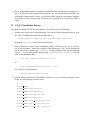
• A Perl distribution, Version 5 or higher. It must be possible to start the executable using the
command:
/usr/bin/perl
This can be either the executable program or a link to the executable.
• Any version of GNU make. This is required to compile your CO 2 P3 S distribution.
• A computer with an active network connection. CO2 P3 S uses XML documents to store relevant program and tool configuration information, and the document descriptions are accessed
via the World Wide Web. It is possible to work around this requirement; see Section 4.7 for
details. Also, the network connection is required to use the distributed CO 2 P3 S environment
[6].
2
• If you want parallel speedups, you will need a shared memory multiprocessor computer system. CO2 P3 S will work on uniprocessor machines, but you will not likely experience any
performance improvements. In fact, you will most likely experience performance degradation. However, when testing for the correctness of a program, such a system may still be
useful.
2.3 CO2 P3 S Installation Process
To compile and install CO2 P3 S on your computer, you will need to do the following:
1. Obtain a copy of the source code distribution. This comes as either a gzipped tar file or a zip
file. This is available through the World Wide Web at:
http://www.cs.ualberta.ca/∼systems/cops/index.html
through the Downloads link on the left–hand frame.
2. Select a directory for your CO2 P3 S installation, which we will refer to as COPSDIR for the
rest of this document. Extract the contents of the distribution. The CO 2 P3 S distribution
will unarchive into a subdirectory “copsProj”. For the gzipped tar file, use the command
(where “%” is your shell prompt, and replacing copsDistribution.tar.gz with the
name of the distribution file):
% tar xvfz copsDistribution.tar.gz
or
% zcat copsDistribution.tar.gz | tar x
For a zip file, use the command
% unzip copsDistribution.zip
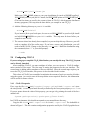
3. Add the following directories and JAR files to your CLASSPATH variable, using the correct
means for your operating system or shell:
• .
• COPS HOME
• COPS HOME/libs/jdom.jar
• COPS HOME/libs/xalan.jar
• COPS HOME/libs/xerces.jar
• JAVA HOME/lib/tools.jar
• COPS HOME/jini1 1/jini-core.jar
• COPS HOME/jini1 1/jini-ext.jar
• COPS HOME/jini1 1/jini-code.jar
3
• COPS HOME/jini1 1/norm.jar
Make sure COPS HOME points to your cops installation dir (such as $HOME/copsProj),
JAVA HOME points to your jdk1.4.1 install, and JINI HOME points to COPS HOME/jini1 1
(The last four items are used by the current release of CO2 P3 S, which supports distributed
memory programs.) This step must be done before you compile or run CO 2 P3 S.
4. Add the following directory to your PATH variable:
• COPS HOME/binUtil
If you install a jdk in your local space, be sure to set $JAVA HOME to your local jdk install
and add $JAVA HOME/bin to your PATH variable. This step must be done before you
compile or run CO2 P3 S.
5. The current release has already been compiled, so you can skip this step. However, you still
need to complete all of the earlier steps. If you have a source–only distribution, you will
need to build CO2 P3 S. Change to the directory COPS HOME/. Build the distribution using
the command (where “%” is your shell prompt):
% make
2.4 Configuring CO2 P3S
If you are using a pre-compiled CO2 P3 Sdistribution, you can skip this step. The CO2 P3 Ssystem
can be directly launched.
After compiling CO2 P3 S, you must configure it before you can execute it. CO2 P3 S configuration consists of two stages. The first stage is setting the properties for the user interface. The
second stage is adding pattern templates to the user interface. Since the second stage requires you
to run the CO2 P3 S user interface, this process is also described in this section.
This release of CO2 P3 S was assembled to minimize the amount of work you need to do before
using the system. As a result, some of the steps below are not required. However, this information
will be useful for future releases.
2.4.1 CO2 P3 S Properties
First, copy the file COPS HOME/copsProj/copsrc.xml to $HOME/.copsrc.xml (note
the extra period). $HOME is your home directory as defined by the Java system property user.home.
If you are unsure about the value of this property, you can get it by printing the result of the Java
method call:
System.getProperties().getProperty("user.home")
In a UNIX environment, this should correspond to your normal home directory.
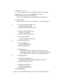
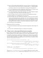
Copy the file $COPS HOME/.copsrc.xml to $HOME/.copsrc.xml. The default file is
shown in Figure 1. This file contains configuration properties used by the CO 2 P3 S graphical user
4
<?xml version=“1.0”?>
<!- - This is a sample RC file for the CO2P3S program. The location
for this file on the user’s system is $HOME/.copsrc.xml - ->
<!DOCTYPE CopsCfg:copsCfg SYSTEM
“http://www.cs.ualberta.ca/∼systems/DTD/1.0/CopsCfg.dtd”>
<CopsCfg:copsCfg
xmlns:CopsCfg=“http://www/cs.ualberta.ca/∼systems/cops/cfg/”>
10
<CopsCfg:copsInstallationDirectory>
installation path of COPS
</CopsCfg:copsInstallationDirectory>
<CopsCfg:userProgramDirectory>
path to user programs
</CopsCfg:userProgramDirectory>
20
<CopsCfg:defaultEditor>
name of default Java code editor
</CopsCfg:defaultEditor>
<CopsCfg:htmlBrowser>
name of HTML browser
</CopsCfg:htmlBrowser>
30
<CopsCfg:patterns>
<CopsCfg:patternName>Mesh</CopsCfg:patternName>
<CopsCfg:patternName>Distributor</CopsCfg:patternName>
<CopsCfg:patternName>Phases</CopsCfg:patternName>
</CopsCfg:patterns>
<CopsCfg:jiniPolicyDirectory>
install path of COPS/Distributed/JINI/policy/policy.all
</CopsCfg:jiniPolicyDirectory>
<CopsCfg:jiniLUSAddress>
URL for lookup service
</CopsCfg:jiniLUSAddress>
</CopsCfg:copsCfg>
Figure 1: The default XML file that comes with a CO2 P3 S distribution.
5
interface. Some of these properties must be filled in before CO2 P3 S can be run. Some can be reset
or must be set through the user interface.
The first part of the XML file consists of header and definition information. You should not
find it necessary to change any part of the first 9 lines (with one possible exception). Lines 1 is
header information regarding the XML file. Lines 2 and 3 are a comment indicating the purpose
and location for this file. Line 4 and 5 indicate where the DTD (Document Type Definition) file
for this document can be found. The DTD file indicates the format of the XML file, including all
legal tags. Since this file is referenced through a URL, your machine must have an active network
connection for CO2 P3 S to work properly. See Section 4.7 for a workaround if you plan to use
CO2 P3 S on a machine that cannot access this URL. Lines 7 and 8 define a name space for the
XML document. CO2 P3 S will work properly if you cannot access this URL.
The region of interest in the .copsrc.xml file starts at line 10 and ends at line 39. The
format of the configuration fields is that of standard XML. Each field starts with the XML tag
<CopsCfg:fieldName>
where fieldName is the name of the configuration field. The field ends with the tag
</CopsCfg:fieldName>
where fieldName must match the starting tag. The value of the field is contained between these two
tags. Tags can appear inside of other tags, but they must be properly nested.
The current CO2 P3 S configuration has the following fields:
copsInstallationDirectory This is the path to the CO2 P3 S installation. This field has to be filled in
manually, before CO2 P3 S is run the first time. The correct value for this field is $HOME/copsProj.
From this point onward, COPSINSTALL refers to this directory.
userProgramDirectory This is the full path of default directory for your CO 2 P3 S programs. If
no value is entered or the supplied directory does not exist, your home directory (as defined
earlier in this section) is used. This can be entered either here or through the user interface.
However, because of interface limitations (described in Section 4.7), it should be filled in
before you open or create a program in CO2 P3 S for the first time.
defaultEditor This is the name of your favourite text editor. This editor is used to edit extra
program files that you wish to incorporate into a CO2 P3 S program. This field can be entered
now or entered later using the CO2 P3 S interface. Note that the selected editor must execute
in its own window, as CO2 P3 S will not do this for you. For editors such as emacs and
gvim, this is not a problem. On the other hand, vi does not start its own window. On X11
systems, this can be remedied by specifying
xterm -e vi
as the value of this attribute. You can replace vi with other console–based editors.
htmlBrowser This is the name of your favourite HTML browser. This browser will be used to
display HTML documentation for the design pattern templates in CO 2 P3 S. This field can be
entered now or entered later using the CO2 P3 S interface. As with the editor, this browser
6
must execute in its own window, so browsers such as lynx must be started the same way
that the vi editor is above. However, most of the documentation pages also include graphics,
so a graphical browser is best.
patterns This field contains a list of the current pattern templates that have been loaded into the
CO2 P3 S interface. You should not change this field manually. It will be updated as you
add and remove templates in the interface, as described in Section 2.4.3. This field already
includes entries for the three pattern templates provided with this distribution of CO 2 P3 S.
jiniPolicyDirectory This field is for the distributed CO2 P3 S that includes distributed pattern templates.
jiniLUSAddress This field is for the distributed CO2 P3 S . You can set the IP address of any
workstation you want use to start up Jini infrastructure components.
Line 39 ends the configuration file.
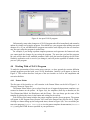
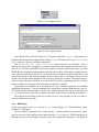
2.4.2 Running CO2 P3 S
To run CO2 P3 S, use the script supplied with the distribution. This script can be found at
COPS HOME/runCops
It can be executed from this location, or copied to a directory within your normal path for executables. When CO2 P3 S is run, a log file cops.log is created in the current directory. This file
logs events and errors in the user interface. If you experience problems, you can view the log by
selecting View Log from the File menu.
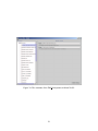
The initial screen for CO2 P3 S is shown in Figure 2. For the remainder of this section, the
menus at the top of the window are the points of interest.
2.4.3 Adding Pattern Templates to CO2 P3 S
When you first start CO2 P3 S, it will have twelve pattern templates already installed: the Abstract
Factory, the Composite, the Decorator, the Observer, the Singleton, the Phases, the Distributor,
the Distributed-mem version of Distributor, the Two–Dimensional Mesh, the Distributed-mem of
Mesh, the Wavefront, and the Distributed-memory version of Wavefront. These twelve pattern
template will appear when you create a new program or open an existing one. You can use these
templates in your programs. However, CO2 P3 S is an extensible system that allows you to add new
pattern templates as they are developed. Later distributions will include tools to help you create
your own pattern templates, and we hope to create a repository for you to exchange your templates
with other users.
The process of adding a new pattern template is best done from the initial CO 2 P3 S screen
(Figure 2), as follows:
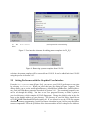
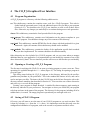
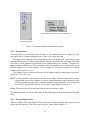
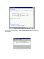
1. Select the Environment menu from the menu bar on the top of the interface. Then select
Import Pattern, shown in Figure 3(a).
7
Figure 2: The initial screen of CO2 P3 S.
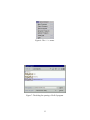
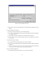
2. After you select Import Pattern, the dialog in Figure 3(b) will appear. You use this dialog to select a pattern template to import. By default, this dialog looks for pattern templates
in the directory COPSINSTALL/patterns, which is where the templates bundled with
your CO2 P3 S distribution can be found. If you have downloaded other patterns, navigate to
the directory where you have installed them.
3. Once you have navigated to the appropriate directory, select the XML file for the pattern
template you wish to add. Select it and click OK, and wait for the template to load. This
process can take some time, as the contents of the XML file are used to generate Java source
code which is then compiled.
4. You can repeat the last two steps for all pattern templates you wish to add.
5. As the interface instructs you, quit CO2 P3 S (by selecting Quit from the File menu). The
new pattern templates will be available the next time you start CO2 P3 S. (This is why we
recommend you add new templates from the initial screen, so you don’t interrupt work on a
current program.)
2.4.4 Removing Pattern Templates from CO2 P3 S
If you decide that a pattern template is no longer useful, you can remove it from CO 2 P3 S. As with
adding a template, this can be done from the initial CO2 P3 S screen. However, if you do so, you
will not be able to modify any programs that use that pattern template.
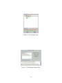
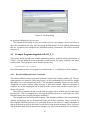
To remove a pattern template, select the Environment menu item from the menu bar at the
top of the interface. From this menu, select Remove Pattern (Figure 3(a)). This is a cascaded
menu item, where the items that appear are a list of the currently imported pattern templates.
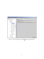
Select the pattern template that you wish to remove, as shown in Figure 4. After you confirm your
8
(a) The
menu.
(b) The pattern file selection dialog.
Environment
Figure 3: User interface elements for adding pattern templates in CO2 P3 S.
Figure 4: Removing a pattern template from CO2 P3 S.
selection, the pattern template will be removed from CO2 P3 S. It can be added back into CO2 P3 S
using the process in Section 2.4.3.
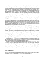
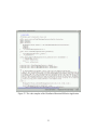
2.5 Setting Preferences with the Graphical User Interface
From the Environment menu (Figure 3(a)), you can set your CO2 P3 S preferences at any time
by selecting Preferences. When you select this item, the dialog in Figure 5 appears. This
dialog allows you to set the userProgramDirectory, defaultEditor, htmlBrowser, jiniPolicyDirectory, and jiniLUSAddress properties described in Section 2.4.1. The remaining properties cannot be set through this dialog. You have to set User program Directory to make it point to
your local directory which contains all CO2 P3 Sprograms. Change the default value in the dialogue to the absolute address of your directory. The directory of your Jini Policy should be set
to COPS HOME/Distributed/JINI/policy/policy.all. If you choose to use the CO 2 P3 Sto support
distributed-memory programming, you need to choose a machine in your LAN to setup Jini infrastracture components. Fill in the ip address of the chosen machine in Jini Lookup Service Address.
9
Figure 5: The Preferences dialog.
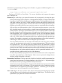
3 About CO2P3S
This section describes some of the more general details of the CO2 P3 S parallel programming system. This includes information on the execution environment for your programs and the programming model supported by the tool.
3.1 Execution Environment
CO2 P3 S generates multithreaded as well as multiprocess Java code for the supported parallel design pattern templates. This code can be run on a uniprocessor or shared memory multiprocessor
or networks of workstations or clusters. On a multiprocessor system, you can used native threads,
which allows the Java Virtual Machine to map the threads to different processors. This will hopefully result in performance improvements, by using different processors to execute different parts
of your program in parallel.
CO2 P3 S assumes that there is an active network connection. This connection is used to verify
the validity of some of the XML files contained within the CO2 P3 S system. Section 4.7 contains
instructions for removing this dependency if you need to.
For shared-memory programming, CO2 P3 S has no special requirements regarding file systems.
Applications that use disk will need to make sure files are available to all threads that need them.
On most shared memory machines, this should not be an issue. However, if CO 2 P3 Sis used to
support distributed-memory programming, we assume that a user’s logins into different machines
on the network have access to the same directory in the file system. This is to guareentee java
classes can be loaded by using the same script on different machines.
3.2 Programming Model
The programming model for CO2 P3 S consists of three layers of user–accessible abstraction. Each
layer provides distinct abstractions supporting different phases of program development. In addition, each layer gradually exposes more implementation details of the object–oriented framework
code generated by CO2 P3 S, providing openness (which, in this sense, means that you can access
low–level structures and run–time code to improve the performance of your application). More
10
information on programming in CO2 P3 S can be found in our papers available through the Publications link at
http://www.cs.ualberta.ca/∼systems/cops/index.html
The layers of CO2 P3 S are listed below. The current distribution only supports the topmost
layer. The layers are:
Patterns Layer At this layer, you express the structure of your program by selecting the appropriate parallel design pattern templates. A design pattern template is a design construct that
represents a family of related design pattern implementations. Each implementation has the
same basic structure, but each is a slight structural variation that makes the pattern more
applicable to your specific problem. To select the member of the family that best suits your
problem, you provide values for pattern template parameters associated with each template.
After you have provided appropriate values for the pattern template parameters, you use the
fully–specified template to create an object–oriented framework that implements the selected
pattern structure. An object–oriented framework is a set of (usually) abstract classes that
provide a design and partial implementation of the application–independent part of a specific
kind of application, such as a graphical user interface. In our case, the application domain
is the implementation of a parallel structural pattern. The structural part of the framework
calls a set of hook methods at execution points where application–specific operations are
required. You complete a program by providing implementations of these hook methods by
subclassing the framework classes and overriding the required methods.
For our parallel frameworks, the structural code includes all of the error–prone communication and synchronization code required by a pattern implementation. The hook methods
are sequential code. They do not require any parallel code for the framework to operate
correctly. In many programs, the hook method code for a generated framework can be taken
directly from an existing sequential program, possibly using the Adapter design pattern [1].
Documentation on the pattern template parameters and the generated framework code is
provided with each template and is not part of this document.
To reduce the possibility of programmer error, the structural framework code is encapsulated
away from you at this layer of development. Other errors are prevented through the user
interface, which is illustrated in Section 4.
Intermediate Code Layer This layer provides a high–level explicitly parallel programming language based on a superset of an existing language, such as Java or C++. It provides high–
level abstractions for expressing parallelism and synchronization.
At this layer, the structural framework code generated at the Patterns Layer is made available,
implemented in the high–level language. You can optimize the code or implement a pattern
variation that is not supported by the template parameters. Alternately, you can skip the
Patterns Layer and write programs directly in this language.
Native Code Layer This layer provides a base object–oriented programming language together
with any libraries used to implement the abstractions in higher layers. The libraries can be
optimized for your particular execution environment.
11
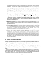
4 The CO2P3S Graphical User Interface
4.1 Program Organization
A CO2 P3 S program is a directory with the following subdirectories:
src This subdirectory contains the complete source code for a CO 2 P3 S program. This code includes both the generated source code and additional source file you add to your program
(Section 4.4.3). You should use the CO2 P3 S user interface to work on all of these source
files. Otherwise, any changes you make may be overwritten during source code generation.
classes This subdirectory contains the Java bytecode files for the program.
cops patterns This subdirectory contains saved information on the pattern templates in your
CO2 P3 S program. You should not change any of the contents of this directory.
cops html This subdirectory contains HTML files for the classes with hook methods for a given
framework. Again, the contents of this subdirectory should not be modified.
cops methods This subdirectory contains the bodies of the application–specific hook methods
that you have implemented. The contents should not be altered manually.
Other directories are also included in a CO2 P3 S program, and you can create others to manage
additional data for your application. It is important that you not modify the contents of any of the
above directories by hand. The user interface provides safe access to the files that you can modify.
4.2 Opening or Creating a CO2 P3 S Program
The first step in working with CO2 P3 S is to open an existing program or create a new one. These
operations are available through the File menu (Figure 6). The dialog for opening a program is
given in Figure 7.
This dialog starts looking for CO2 P3 S programs in the directory indicated by the userProgramDirectory attribute in your preferences. This is the standard file chooser in Java, and can be
used to navigate your files. The items with the CO2 P3 S logo on the left are directories with a subdirectory structure matching that described in Section 4.1. You can select one of these directories
and select Open to work on that program.
Creating a new program is almost identical. A similar file chooser appears, again starting in
the directory indicated in your preferences. You navigate to where you would like your program
to be kept and enter in the name of the program. The directory for the program, including all of its
subdirectories, is created. The empty program is opened and you can begin work on it.
4.3 Saving a CO2 P3 S Program
Of course, you will want to save the state of your CO2 P3 S programs as you work on them. This
is done by selecting Save from the File menu. It is important to note that this only saves the
configuration information of a program, such as the current set of patterns and their values.
12
Figure 6: The File menu.
Figure 7: The dialog for opening a CO2 P3 S program.
13
Figure 8: An open CO2 P3 S program.
Unfortunately, many other changes to a CO2 P3 S program take effect immediately and cannot be
undone by simply not saving the program. You should save your program after making structural
changes to it, or you will find that the program state and the state displayed in the user interface
may not agree when the program is opened later.
For example, if you change a pattern template parameter and regenerate the framework code,
you cannot undo the changes by not saving the program. The next time you load the program,
the code will be that for the modified parameter value while the interface displays the old value.
Similarly, application code is saved as you change it, and will persist regardless of whether or not
you save your program.
4.4 Working With a CO2 P3S Program
To make the presentation of this section more concrete, we have opened the reaction–diffusion
example programs provided with your CO2 P3 S distribution. Initially it will appear as shown in
Figure 8. This section describes each part of the user interface as well as the compilation and
execution facilities.
4.4.1 Pattern Palette
The first part of the interface we will examine is the Pattern Palette on the left of Figure 8. A
closeup is shown in Figure 9(a).
The Pattern Palette allows you to select from the set of support design pattern templates, represented as buttons on the palette. In Figure 9(a), the templates (from top to bottom) are the
Two–Dimensional Mesh, the Distributor, and the Phases. You can always get the name of the
template by placing the cursor in the button and waiting for the tool tip.
Left–clicking on a button includes the pattern template into the current program. The pattern
will appear in the Program Pane (Section 4.4.2) and in the Pattern Pane (Section 4.4.4). Right–
clicking on a button brings up the background menu, shown in Figure 9(b). You can add the pattern to the program (Insert Pattern) or view the pattern template documentation (Pattern
Help) using the HTML browser specified in your preferences.
14
(b) The background menu for the pattern templates.
(a) The Pattern Palette.
Figure 9: The Pattern Palette and background menu.
4.4.2 Program Pane
The Program Pane is the middle section of Figure 8. An expanded picture is in Figure 10. This
pane shows the set of pattern templates that are part of the current program.
The topmost item, with the CO2 P3 S logo followed by the program name, represents the entire
program. Beneath it is a list of the pattern templates that are used in the current program. Each item
in the list is a small graphical representation of the template followed by its name. The name of a
pattern template is based on one of its parameter values, which allows you to distinguish between
different instances of the same template. In our example, we are using an instance of the Mesh
template with the name RDMesh.
The Program Pane also indicates the status of each pattern template using colours for the template name. The colours are:
Red This colour indicates that the framework code is out of date. This either means that you have
not generated code for this template, or you have changed a pattern template parameter value
and the generated code may not be consistent with the current parameters. You can generate
code from the Pattern Pane (Section 4.4.4) or the Compile dialog (Section 4.4.5).
Green The framework code is consistent with the current parameter values.
The meaning of these colours is indicated by the legend that appears at the bottom of the Program
Pane.
4.4.3 Program Options Pane
When the topmost item in the Program Pane is selected, the Program Options Pane appears on the
right side of the interface. This is the case in Figure 8, shown again in Figure 11.
15
Figure 10: The Program Pane.
Figure 11: The Program Options Pane.
16
Figure 12: The Pattern Pane, showing an instance of the Mesh pattern template.
The Program Options Pane allows you to provide information for the entire program. This
consists of two components: user classes and program comments.
User classes, the top part of the Program Options Pane, let you create additional classes for
your application. In all CO2 P3 S programs, you will need to supply a mainline class, but other
classes (perhaps from sequential versions of your program) can also be included. In addition to the
mainline, the reaction–diffusion example uses three additional classes. You can add new classes
using the Add New Class button, where you will be prompted for the name of the new class.
This should be entered without the .java suffix. You can select a user class and delete it from
the program. You can also select a class and edit it using the editor in your preferences.
The bottom part of the Program Options Pane provides space for program comments. In Figure 11, this space is used to provide information on the command line arguments for the program.
4.4.4 Pattern Pane
If you select one of the pattern template instances in the Program Pane, the Program Options Pane
is replaced by the Pattern Pane for the selected instance of a pattern template. The Pattern Pane on
an instance of the Mesh is shown in Figure 12.
The Pattern Pane shows details on a specific instance of a pattern template, such as the current
values of its parameters. This information is depicted using a combination of text and graphics.
In Figure 12, we can see several class names (RDMesh and MorphogenPair) as well as other
parameter values (a four–point mesh, a fully–toroidal topology, and an ordered computation).
The Pattern Pane is also used to work with the pattern template and generated framework code.
The pane allows you to change parameter values to refine the template, generate code from a fully–
specified template, and insert hook method bodies to complete the implementation of a program.
Some aspects of this functionality are common to all pattern templates and are discussed here.
Other aspects are necessarily specific to a particular pattern template and are covered in more
detail in the template documentation.
The pattern template is refined using a background menu in the Pattern Pane, obtained by right–
clicking anywhere in the pane. The menu for the Mesh pattern template is shown in Figure 13. The
operations in this menu can be broken down into three categories: generic operations that apply to
all pattern templates, pattern template class names, and pattern template parameters. The latter two
17
Generic
Operations
Pattern Template
Class Names
Pattern Template
Parameters
Figure 13: The background menu in the Pattern Pane.
Figure 14: The background menu for the Pattern Pane with multiple viewable templates.
categories are specific to each pattern template and are discussed in the template documentation.
The first menu item in the generic operations, Generate First Layer Code, generates
Patterns Layer code from the pattern template using the current template parameter values. If code
is successfully generated, the label for the template in the Program Pane will turn green. The
Generate Next Code Layer item is disabled since this release only supports the Patterns
Layer. It will be enabled in the future when there is more support for the two lower layers in the
CO2 P3 S programming model.
The last menu item in the generic operations, Delete Pattern, deletes the current pattern
and associated files from your program. Note that this deletion takes place immediately and cannot
be undone later.
The middle menu item is View Pattern Template. This item allows you to add hook
method bodies to generated framework code, and so is only available when the generated framework code is up–to–date. Selecting this item brings up a Viewing Template window, shown in
Figure 15, that allows you to view and edit hook method bodies for the current framework. If there
are multiple classes in a framework that have hook methods, this item becomes a cascaded menu
item (indicated by an arrow to the right) and you can select the class you wish to edit (Figure 14).
Either a new viewer for the class will appear, or an existing viewer for the selected class will be
brought to the foreground.
The Viewing Template window is a modified HTML viewer where the links represent places
where you can add or edit code. The code in the viewer is generated with the framework code for
a pattern template, and is run through a code beautifier before being displayed. If you select a link,
a Code Editor dialog appears, shown in Figure 16.
The Code Editor dialog allows you to modify the code for particular method in the viewer.
This editor is not the one in your preferences, but rather is a dialog that was created specifically to
prevent errors involving hook method signatures. The combination of the Viewing Template and
Code Editor dialogs do not allow you an opportunity to edit the signatures of the hook methods.
Further, the code is generated for you, saving you from having to enter these signatures. This is
18
Figure 15: The Viewing Template for editing application code in the framework generated for a
pattern template.
Figure 16: The Code Editor dialog.
19
important because the remaining framework code relies on the methods in the class in the viewer
having specific signatures for the code to operate correctly. This tool support ensures that these
signatures cannot be changed and prevents some potential compile and logic errors. As an example
of the latter error, consider the first two arguments to the constructor at the top of the code in
Figure 15. These two arguments represent the location in a two–dimensional data structure for
the element being created. If you had to write this signature or were able to change it, you could
accidently reverse the two parameters. This error cannot be caught by the compiler since the
parameter types are correct, which is all the compiler checks. However, the framework code that
uses this constructor is assuming the order in the figure. Reversing the parameters causes the data
to be transposed, which may cause errors later.
In the Code Editor dialog, you can also restore the default implementation of a hook method by
clicking the Restore Default button. This replaces the current value of the hook method with
the default as generated with the framework code. An important note is that, because of a problem
with the current implementation, the code editor does not display any code for those methods with
the default implementation. The correct method body is still in the actual source code, but is not
displayed in the code editor. However, if you click OK on a code editor with an empty body, you
will overwrite the default with a blank body. This will cause compilation errors later. To preserve
the default, either cancel the change or restore the default.
After restoring the default or accepting a new method body, CO 2 P3 S will normally regenerate
source code for the framework to incorporate this new code, and display the updated code in the
viewer. This regeneration can incur an unwelcome time delay. You can disable this regeneration by
unchecking the Regenerate After Each Change checkbox at the bottom of the Viewing
Template. This speeds up the code editing process. Changes to method bodies are no longer
reflected in the viewer. However, the changes are still visible in the code editors. If any methods
are changed, the background of the viewer will turn grey and a label will appear at the bottom of
the dialog, making it is clear that the displayed code is out–of–date. An out–of–date viewer can
be refreshed by rechecking the Regenerate After Each Change. Closing an out–of–date
viewer (by clicking the Close button) will force a code regeneration, so current code will appear
if the template is brought up again later.
Checking the Show Line Numbers checkbox at the bottom of the Viewing Template window cause line numbers for the source code to appear on the left side of the viewer. This feature
allows you to easily find compile errors in the code in this window.
Note that if you regenerate the framework code, using either the Generate First Layer
Code menu item or the option in the Compile dialog (Section 4.4.5), all Viewing Template and
associated Code Editor dialogs for that pattern template are closed. It is possible for you to change
some of the class names in the generated code, which may mean that the class displayed in the
viewer may no longer be part of your program. The best way to ensure that this window always
displays a relevant class is to close it and have you open another viewer, which will always be on
a class that is part of the current framework.
4.4.5 Compile Dialog
Once you have entered all of your application code, you need to compile the code. This is done by
selecting the Compile item from the Program menu, shown in Figure 17.
20
Figure 17: The Program menu.
Figure 18: The Compile dialog.
The Compile dialog, shown in Figure 18, will appear. Selecting Compile will compile you
program with the arguments supplied in the dialog. Clean will remove all of your .class files.
Abort stops any currently executing compilation.
The Regenerate All Layer One Source button performs two functions. First, it
removes all source files (except the user classes entered using the Program Options Pane (Section 4.4.3)), class files, and HTML files for the program. Second, it regenerates source code and
HTML files for all patterns in the program using the current values of the pattern template parameters. The reason for this is that CO2 P3 S may keep source files that were generated based on old
values of class names. We currently compile all source files in the src directory. However, these
old files can interfere with compilation if the code they contain is out of date. This button lets you
clean out these old source code files. It is also useful for quickly regenerating code for all of the
pattern templates in a program rather than doing it template by template.
Arguments to the compiler can be specified in two ways. Common arguments, for including
debugging information (-g on the command line), deprecation warnings, optimizations, and verbose output can be indicated with the check boxes. Additional arguments can be inserted into the
Flags text field. The output of the compiler will appear in the text area at the top of the dialog.
The contents of this dialog are also saved when you save your program, so you won’t have to
enter this information each time.
4.4.6 Run Dialog
To run your program, select Run from the Program menu (Figure 17). The Run dialog, shown
in Figure 19, will appear.
The Run dialog is much like the Compile dialog. Common options are provided as check
boxes or text areas. Other options can be entered into the Flags text area. The Run dialog has an
additional text area for specifying the mainline class and command line parameters. The output of
21
Figure 19: The Run dialog.
the program is displayed in the text area.
The contents of this dialog are also saved when you save your program, so you won’t have to
enter this information each time. The Run dialog for Distributed CO2 P3 Sis slightly different than
this one, it contains extra settings for the distributed-memory environment. This will be described
in Section 5.
4.5 Example Programs Supplied with CO2 P3 S
This section briefly describes the example applications that are supplied with this distribution of
CO2 P3 S: reaction–diffusion texture generation, parallel sorting by regular sampling, and matrix
product chain. These programs can be found in the directory
COPSINSTALL/programs
More information on these two programs is provided in the docs subdirectory for the program.
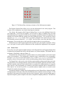
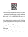
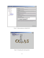
4.5.1 Reaction–diffusion Texture Generation
The reaction–diffusion texture generation problem is taken from computer graphics [4]. The program simulates two chemical, called morphogens, as they simultaneously react with one another
and diffuse over a two–dimensional surface. This simulation repeatedly iterates over the surface,
computing new values, until the values converge to their final solution. When the simulation is
complete, one of the morphogens can be used to render a texture that resembles zebra stripes, as
shown in Figure 20.
This texture is generated so that it can be tiled on a larger surface without any noticeable edges
between tiles. This is accomplished by allowing the diffusion process to wrap around the edges,
both horizontally and vertically, during the simulation.
This program uses the Mesh pattern template. This template parallelizes this computation by
spatially decomposing the two–dimensional surface into distinct partitions. These partitions are
then assigned to different processors for evaluation. However, the nature of a mesh computation is
that each element (or pixel in the texture) requires data from adjacent elements. Thus, each partition needs data from adjacent partitions to compute new values for the elements on its boundary.
22
Figure 20: The output of the reaction–diffusion texture generation.
Further, for each iteration, the new values for the elements are computed using the values from the
previous iteration, which requires barrier synchronization to ensure that no processor computes too
far ahead.
The example program executes the simulation (based on a set of command line parameters that
are explained in the Program Options Pane of the program). The initial, random conditions are
displayed in a window. When complete, the final result is displayed. This window is the only
output of the program. You can use image manipulation software to capture this image for later
use.
To end the program, you will need to kill this window. Otherwise, the Run dialog will still
believe the program is executing.
An interesting note on this program is the reuse of code from the sequential version. All of
the classes in the Program Options Pane except the Main.java class were taken directly from a
sequential implementation of this program. The hook method code is used as an Adapter pattern
[1], essentially translating the interface in the generated framework code to the interface required
by the reused code. In addition to reusing sequential code, this implementation strategy also keeps
the hook method code simple.
4.5.2 Parallel Sorting by Regular Sampling
The second example program implements the Parallel Sorting by Regular Sampling (PSRS) algorithm [2]. This program sorts a specified number of uniformly distributed, random Integer
objects and verifies the results. This is an explicitly parallel sorting algorithm that does not have
a direct sequential counterpart. In addition, this program uses two instances of the Phases and
Distributor pattern templates, providing an example of composing multiple frameworks into a
complete application.
Composing frameworks in CO2 P3 S is simplified because each framework uses the Facade pattern [1] to provide a single, simple interface to the code. The constructor for this Facade creates
all of the objects needed by the framework and assembles them into a complete program, simplifying the instantiation process. The Facade also provides a simple interface for launching the
computation for the framework where applicable (seen in the Phases and Mesh frameworks).
23
4.5.3 Matrix Product Chain
The final example is matrix chain product, one of the Cowichan problems [3]. This program uses
a dynamic programming matrix to find the least expensive way to multiply a set of matrices. The
program uses a single instance of the Wavefront pattern template, computing the upper half of a
matrix starting from the diagonal and working to the top right corner.
4.6 Disabled Interface Options
This version of CO2 P3 S does not have all options enabled. To minimize the number of changes for
future versions of CO2 P3 S, most of these options are permanently grayed out in this distribution.
These options are:
• The Create or Edit Pattern menu item in the Environment menu. This is provided for modifying and create pattern templates (Section 6).
• The Tools menu item on the user interface is disabled. These tools are for managing machines and resources in the forthcoming distributed memory version of CO 2 P3 S (Section 5).
• The Shared Memory and Distributed Memory radio buttons in the Run dialog.
Shared memory is always selected.
• The Generate Next Code Layer in the background menu in the Pattern Pane. This
release of CO2 P3 S only supports the Pattern Layer, so this menu item is disabled.
4.7 Caveats
There are a number of issues with the CO2 P3 S user interface. These problems, and potential
workarounds where possible, are:
1. When editing hook methods in the Viewing Template window, the code for the complete
framework is regenerated after each method body is accepted. The time for this generation
may be longer than you wish to wait. To prevent this regeneration, uncheck the Regenerate After Each Change checkbox. The window will let you know if the code in the
window is out of date. Note, though, that the most recent code will be displayed in the Code
Editor dialog. It simply won’t be shown in the viewer itself. If you recheck this checkbox or
close the viewer with out–of–date code, the framework will be regenerated.
2. When you regenerate the complete framework, using either the Generate First Code
Layer menu item in the Pattern Pane or the Regenerate All Layer One Source
button on the Compile dialog (but not if you’ve changed a hook method body), all template
viewers and code editors are closed. We cannot check to see if the class in the viewer is
still relevant in the application, or if the correct code is being displayed. Closing the viewers
and reopening them from the Pattern Pane menu ensures that the viewers always display the
most recent version of a class, and that the class is still relevant to the application.
24
3. Using X11, the graphical user interface may not correctly display over a remote X connection. You will need to run CO2 P3 S on the local machine. As far as we can tell, this is a
problem in the Swing library used for the interface.
This means that you will not be able to use the Run dialog to execute your CO 2 P3 S program.
Instead, you can run the program manually. In the classes directory for your program
(Section 4.1) are the class files for your program. You can start the virtual machine using
these files, or copy them to other machines as necessary.
4. Using X11, some window managers do not correctly display the user interface, even on the
local machine. Once again, this appears to be a problem with Swing. In particular, we have
experienced serious problems with the FVWM2 window manager, including the following:
• The region around the edge of dialog boxes does not render properly, instead appearing
as a blank grey region. This may obscure the buttons in the dialog. The buttons are
still present and can be clicked, but you will not be able to see what you’re clicking.
Usually, resizing the dialog will correct this. Another option is to iconify and expand
the window, but again this doesn’t always work.
• The size of a dialog window may change each time it is brought up. The dialog may
grow slightly each time until it takes up the entire screen. It may shrink slightly until it
is too small for all of its components.
The problems with FVWM2 are apparently known bugs, but fixes do not appear to be forthcoming. The screenshots for this document were all taken using the Enlightenment window
manager running under the Gnome desktop on a Linux workstation. We have not experienced any problems with this environment. We cannot vouch for other desktop and window
manager combinations.
5. The file list dialog hangs when working on directories with a large number of files. This is
why we recommend that you set the userProgramDirectory attribute (Section 2.4.1), either by
modifying the .copsrc.xml file manually or through the Edit Preferences menu
item in the user interface.
6. There are a number of exceptions that are thrown by Swing components. Most of the time,
these can be safely ignored. Unfortunately, this can make it hard to find the exceptions that
are important.
7. Saving a CO2 P3 S program saves the configuration information for an individual program.
However, changes within the program are performed immediately, regardless of whether
you save the configuration or not. For example, deleting classes or changing hook method
bodies take effect immediately and cannot be undone by not saving the program. This also
means that it is possible for the configuration and program code to be out of step with one
another. We should perhaps follow the emacs approach of creating a working copy and
replacing the original when you save the program, but this has not been done.
8. CO2 P3 S requires an open network connection to start. The reason for this is that the format
of the .copsrc.xml file is verified using a DTD (Document Type Definition) file that is
25
accessed through the World Wide Web. Line 5 of Figure 1 shows the URL of this file. If you
will be using CO2 P3 S on a computer without a network connection, you should change this
URL to point to the copy of the DTD file included in the CO2 P3 S distribution. Change the
URL to the following:
file:COPSINSTALL/DTD/CopsCfg.dtd
where COPSINSTALL is the directory of your CO2 P3 S installation (the value of the copsInstallationDirectory configuration property from Section 2.4.1).
9. When editing code using the Viewing Template, the code for methods that still have their
default bodies will not appear in the Code Editor. The proper code is still in the application
classes, but simply doesn’t appear in the Code Editor dialog. However, you must take care
not to accept an empty window by clicking OK. This overwrites the default with an empty
method body, which will result in compile errors. Either cancel the change or restore the
default implementation.
10. There are a number of cases when the displayed HTML and the actual code do not match.
The most common example is with the < and > operators. These are not displayed correctly
since they are part of HTML tags. The HTML generator does not convert these for proper
display. In other cases, we have seen extra newlines inserted into code. These problems only
affect the HTML and not the underlying code. The code as it appears in the Code Editor
dialog is properly inserted into the source.
11. If no constructors are explicitly added to a class, the code generator will always insert an
explicit default constructor that is not editable by the user. This can be a problem for pattern
designers, as it means that the user cannot augment the default constructor. (Trying to add
the default constructor in user–added code will result in a compile error.) The workaround is
to explicitly add the default constructor as part of the generated framework code and make
it editable. Another option, which is best for constructors that pass arguments to a parent
constructor, is to create a constructor that cannot be edited and that calls an initialize method
that the user can implement.
5 Distributed CO2P3S
The current release of CO2 P3 S includes a DCO2 P3 S environment which supports distributed parallel programming. DCO2 P3 S is a distributed-memory runtime environment including a flexible
architecture (built by Jini technology), a distributed-synchronization package, a communication
mechanism, a performance monitor and a distributed process controller. All these components
offer runtime support for distributed-parallel applications. Moreover, a set of new distributedmemroy parallel design pattern templates (DM Mesh, DM Distributor, DM Wavefront) are also
created. These design pattern templates facilitate the design of distributed applications which can
be executed under the DCO2 P3 S environment.
26
5.1 Working with the DCO2 P3S environment
This section will introduce the DCO2 P3 S environment. At the end of this section there will be
checklists about using different functionalities of the environment. The DCO 2 P3 S Tools menu in
Figure 21 shows three options—Distributed Environment, Jini Start Up and Jini Shut Down—that
control the DCO2 P3 S environment. The second option launches all Jini infrastructure components
on one or more machines. As DCO2 P3 S is implemented as a Jini distributed system, all these Jini
infrastructure components are necessary to help different components in DCO 2 P3 S to interact and
coordinate with each other [6]. The third option destroys all Jini components in order to shut down
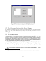
the DCO2 P3 S environment. The first option, launches a configuration window, as shown in Figure
22. The left list box in the window includes all machines that comprise the system. By clicking the
Add, Delete and Delete All buttons, the user can add or remove the machines in the system. The
Launch button triggers all listed machines to launch a series of daemon processes, which will be
manipulated by the central control to provide execution support for distributed programs. The right
list box in the window allows the user to choose one or more machines from the left as participants
for a specific distributed-parallel application. This approach gives the user an option to apply static
load balancing to the application. By monitoring the real-time performance of all machines in the
environment (described later in Section 5.2), the user can choose the most idle ones to use.
Figure 21: Menu options to start up the environment
After the environment is launched, all the underlying details about the distributed parallelism
can be ignored by the programmer, who can use DCO2 P3 S the same as CO2 P3 S. Please refer to
previous sections for descriptions on how to use distributed pattern templates.
In DCO2 P3 S, a generated application consists of a main program and a series of distributed
slave processes. The main program is executed on a central control machine where all GUI stuff
resides. Each process is implemented as a Jini service running on a ditributed machine in the
environment.
27
Figure 22: The window to configure the DCO2 P3 S environment
5.2 The Performance Monitor and the Process Manager
In a distributed system, having central control over distributed processes and remote machines
helps the user easily monitor and dynamically configure the system. We provided such a function
in DCO2 P3 S.
5.2.1 The performance monitor
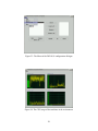
A graphical display of the runtime information of distributed machines helps DCO 2 - P3 S users
monitor the environment to make full use of idle machines and avoid highly loaded ones. Dynamic
load balancing is not supported in current version of DCO2 P3 S as this requires extensive modifications to the Java virtual machine. Rather, by the use of visual information, for most applications
the user can easily improve performance using static load balancing.
The CO2 P3 S environment has to be launched before any system information can be viewed.
As described in 5.1, the Jini infrastructure has to be started first; then certain machines have to
be added to the environment; finally one daemon on each machine will be activated (by clicking
the Launch buttern in 21). These daemons show the runtime performance information of the
environment.
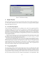
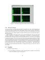
The “system information” menu item of Figure 23 is used to launch graphical displays 1 (Figure
24 and 25).
1
The graphical display stems from a memory monitor in a Java 2D demo canned in the JDK1.2.2 distribution.
28
Figure 23: The Menu of the DCO2 P3 S configuration dialogue
Figure 24: The CPU usage of the machines in the environment
29
Figure 25: The memory usage of the machines in the environment
5.2.2 The Process Manager
A daemon running at each participating machine is responsible for remote process management.
The process manager also helps deliver remote display. Remote display is always a difficult problem in distributed systems because of a lack of low-level control over distributed processes. In our
approach, each process manager gathers the output of all local processes and sends the output to
the central manager.
Figure 26 shows the run dialog used to execute generated applications. The user must clarify
whether an application is intended for a shared-memory environment or a distributed-memory
environment. By clicking the radio box labeled “Distributed Memory”, the DCO 2 P3 S environment
is chosen as the runtime. The user can also specify the maximum and minimum heap size of JVMs
that will be launched on the central control and distributed machines. In the text field labeled “Main
class and command line parameters”, the user specifies the Java class that launches the instantiated
framework and provides necessary command line parameters. After all necessary information has
been specified, the user can click the Execute button to run the application. Application output,
including the results from distributed machines, is displayed in the large text box at the center of
the window.
5.3 Checklists
1. Launch the Jini environment
(a) Go to Enviroment→Preferences, set the Jini lookup Service Address to be the IP address of one machine on your LAN (Figure 5)
30
Figure 26: The run dialog of DCO2 P3 S
(b) Go to Tools→Start Jini, which launches the Jini infrastructure components at above
address
2. Launch the DCO2 P3 S enviroment
(a) Start up the Jini enviroment first, refer to the first checklist
(b) Go to Tools→Distributed Environment, launch the Distributed environment configuration window (Figure 22)
(c) Add machines you want to include in the environment in the left list box
(d) click “Launch” botton to load the daemon class into each machine you add in the
previous step
3. Launch the Performance Monitor
(a) Launch the DCO2 P3 S environment first, refer to above checklist
(b) Go to File→System Information in the Distributed environment configuration window
(Figure 22)
(c) Choose the menu items under the File menu in the Performance Monito window (Figure 24) to see CPU or memory usage of each distributed machine
4. Execute a DCO2 P3 S application
(a) Launch the DCO2 P3 S environment first, refer to the second checklist
31
(b) Open up a generated distributed application, the steps to generate a distributed application are the same as those taken to generate a shared memory or a sequential application. Refer to section 4.4 for more information on creating a CO2 P3 S application.
(c) Go to the Distributed environment configuration window (Figure 22), choose several
machines from the left list box and add them into the right list box.
(d) Go to the Program Menu under the Main Gui (Figure 17), choose Compile to compile
your program. Choose Run to launch the Run dialog (Figure 26).
(e) In the run dialog, choose the execution environment to be distributed environment
(f) change the Heap sizes of distributed processes if necessary
(g) Fill in the Main Class and Command Line Parameters. Please note that for sharedmemory and distributed-memory applications, one of the command line parameters
must indicate the number of threads/processes to be used in the application. For distributed applications, the number of processes you specify in the command line option
must equal the number of machines you add in the right list box (Figure 22) in step 3.
(h) Click Execute to run the application
5. Shutdown the DCO2 P3 S environment
(a) Shut down all daemons in the DCO2 P3 S environment coniguration window (Figure 22)
first
(b) Go the Tools→Jini Shutdown (Figure 21) to destroy Jini components
5.4 Things to notice when using distributed pattern templates
• Static variable initializations When using a distributed pattern template to create one distributed application, special efforts should be put on static variable initializations. A regular approach in shared-memory applications to initialize static variables is to put initialization code in the Main program. For example, in the Main program of the shared-memory
Reaction-diffussion application, the following code is used to create two instances of class
SpecificMorphogenConstants.
SpecificMorphogenConstants m1Constants = new
SpecificMorphogenConstants(MorphogenPair.getGlobals(),
2.0d, 1.0d, Math.PI / 4.0d) ;
SpecificMorphogenConstants m2Constants = new
SpecificMorphogenConstants(MorphogenPair.getGlobals(),
2.0d, 1.5d, Math.PI / 4.0d) ;
Random gen = new Random(1) ;
Initializer initializer =
new Initializer(m1Constants, m2Constants, gen) ;
These two SpecificMorphogenConstants instances will be set to two static variales
in class MorphogenPairState, which is a user-template class. The MorphogenPairState
32
Figure 27: The code template of the Distributed Reaction-Diffusion Application
33
class models the node class of the two-dimensional mesh surface in the reaction-diffusion
application. These two static variables are shared among all MorphogenPairState instaces to process the new states of all mesh nodes. This approach is not valid in distributedapplications. Therefore, the user should add the static variable initialization code in the
user template as well as the Main program. Open up the NewDMesh application under
$COPS HOME/programs/DistMemApps/ to view its code template for more information.
27
• Manually launch and shutting down Jini infrastructure components There are two scripts—
launchScript and shutDnScript–under the $COPS HOME/binUtil/jini startup. These two
scripts help launch and shutdown Jini system components. The syntax of launchScript is
“./launchScript ipaddress”, the ipaddress represents the IP address of the machine you wish
all Jini system components to run on. TO shut down these components manually, rsh the
machine and run shutdnScript.
• Runnaway processes There is always a runnaway Jini process after shutting down all Jini
system components. Rsh into the machine that Jini system components were running to kill
that runnaway process.
• The Performance Monitor The Performance Monitor is implemented with JNI and LibGTop—
a C++ library for getting system runtime information. The Performance monitor is tested on
Red Hat Linux 7.1 2.96-98. It may not work properly on other platforms. If there is any
problem launching the DCO2 P3 S environment, please contact us.
• Problem with execution output for distributed applications Currently, DCO2 P3 S only
supports a first-time display of the execution output for a distributed applications. A firsttime display means the output from the distributed processes can only be collected for the
first time after the DCO2 P3 S environment has been launched. Following executions will only
have the output from the main program which runs from the main GUI. To have all output,
the user has to shut down all DCO2 P3 S daemons and restart them. This problem will be
solved in future releases.
6 MetaCO2P3S introduction
Although design patterns try to be generic to cover as many situations as possible, they are still not
comprehensive enough to handle some requirements and ramifications which may appear in future
applications. The limited capacity and extensibility of pattern libraries is one of the major reasons
that pattern-based programming systems have not gained greater acceptance.
CO2 P3 S has addressed this problem by introducing a new tool—MetaCO 2 P3 S. Using MetaCO2 P3 S,
a pattern designer can identify and generate a new design pattern and add it into the CO 2 P3 S pattern
library.
MetaCO2 P3 S provides a means of constructing design pattern templates in a structured way.
Each generative design pattern constructed using MetaCO2 P3 S contains two parts: the GUI part
and the pattern template part. The GUI part allows the user to specify pattern parameters through
a graphical user interface. The pattern template part contains all template code.
34
Figure 28: The pattern editor
Figure 29: The MetaCO2 P3 S GUI
35
Figure 30: The constants of the DM Mesh pattern in MetaCO2 P3 S
36
Figure 31: The GUI configuration of the DM Mesh pattern in MetaCO2 P3 S
37
Figure 32: The structure of the DM Mesh pattern in MetaCO2 P3 S
38
Figure 33: Pattern parameters in MetaCO2 P3 S
Figure 34: Importing and removing patterns
39
The menu item in figure 28 activates the pattern template editor. The pattern editor is opened
with an empty template. The first step to create an empty template is to specify its name and other
two properties. After specifying these three properties, a pattern designer can continue to create
other components of the new pattern.
Figure 29 shows a graphical display of the DM Mesh template in MetaCO 2 P3 S. The left pane
of this figure displays all required components in the template, including constants, classes, parameters and GUI configurations.
The constants and GUI configurations define the GUI part of the pattern template. The constants in Figure 30 describes the text labels that will be displayed on the template GUI as in Figure
12 and 13. The GUI configuration (Figure 31) sets up the graphical display, such as the picture
which shows the pattern’s object structure and the position of the constant labels in the window of
the pattern template that will be used by a programmer. A good practice of using the pattern editor
is to open an existing pattern template and modify it to create another new pattern.
The class names and parameters are the core of each template since they implement a design
pattern using a code template.
The classes consists of all necessary components that contribute to the implementation of a design pattern. Different classes have different attributes, reflecting whether a class contributes to the
private parallel structure or offers hook methods for the programmer to input application-specific
details. The class named DM Mesh in Figure 32 describes the collector class in the DM Mesh
pattern; the collector class is a framework class that encapsulates the structure information and
cannot be accessed by the user.
An important step in creating a design pattern template is to generalize and quantify the descriptive properties of an ordinary design pattern to formal parameters with domain restrictions.
Each pattern parameter has a direct effect on the code that is generated by a pattern template.
After identifying all possible parameters, the pattern designer provides code fragments for each
legal combination of parameters. A design pattern thus becomes a template for a group of frameworks. For example, Figure 33 lists a parameter of the DM Mesh pattern called “ neighbors”,
which specifies how many neighbour nodes (4 or 8) are needed to compute the mesh node.
All design patterns created in MetaCO2 P3 S are stored as XML and Java files, which are easy
to store and share with other systems. Generated pattern templates can be easily imported into a
CO2 P3 S distribution (Figure 34. Patterns can also be removed by choosing the “Remove Pattern”
menu item.
MetaCO2 P3 S was a key tool in constructing DCO2 P3 S to support the generation of parallel
design patterns for a distributed-memory environment. It allowed us to focus on designing efficient
parallel structures, communication and synchronization mechanisms for new distributed-memory
version of patterns.
7 Support for Sequential Design Patterns
CO2 P3 S was originally envisioned as a pattern–based parallel programming system. It has become
clear that these same ideas and programming model are equally applicable to creating programs
with sequential design patterns. By using MetaCO2 P3 S , we successfully added four sequential
patterns (Composite, Decorator, Observer and Singleton) into our pattern template repository. De-
40
tailed introductions of these patterns can be found in [1]. Sample applications using these patterns
are also included in the distribution.
• Breakout: Uses 5 patters: Composite, Observer, Decorator, Singleton and Abstract Factory.
• CompositeParser: builds a parse tree as a composite for simple arithmetic expressions. The
parsing and building of the tree was all done manually, but uses COPS generated code for
three types of traversals: - Unparsing the tree (prints out the original expression fully parenthesized). - Printing the parse tree (each level in the tree is indented more). - Evaluating the
parse tree.
• ListObserver: replaces the ListData event model from Java’s api with an instance of a COPS
generated Observer pattern. It’s a pretty complicated example because I had to take the
source code of several classes from the api and make small changes to it.
• PowerPlant: another Observer pattern. It’s just a toy application, but it’s easier to see the
pattern at work in this program than in the previous one.
• Monitor: replaces System.out with an instance of a COPS generated Sigleton pattern.
• PrefixParser: uses an abstract factory to generate parse nodes in a parser that evaluates arithmetic expressions in prefix notation.
• TableDecorator: decorates a TableModel to sort the elements in the selected column.
8 Feedback
We would appreciate any feedback that you have on the CO2 P3 S parallel programming system, or
reports of any bugs that you find. Please send e–mail to [email protected].
References
[1] E. Gamma, R. Helm, R. Johnson, and J. Vlissides. Design Patterns: Elements of Reusable
Object–Oriented Software. Addison–Wesley, 1994.
[2] H. Shi and J. Schaeffer. Parallel sorting by regular sampling. Journal of Parallel and Distributed Computing, 14(4):361–372, 1992.
[3] G. Wilson. Assessing the usability of parallel programming systems: The Cowichan problems.
In Proceedings of the IFIP Working Conference on Programming Environments for Massively
Parallel Distributed Systems, pages 183–193, 1994.
[4] A. Witkin and M. Kass. Reaction–diffusion textures. Computer Graphics (SIGGRAPH ’91
Proceedings), 25(4):299–308, 1991.
[5] S. Bromling. Meta-programming with Parallel Design Patterns. Master’s thesis, Department
of Computing Science, University of Alberta, 2001.
41
[6] K. Tan. Pattern-based Parallel Programing in a Distributed-Memory Environment Master’s
thesis, Department of Computing Science, University of Alberta, 2003.
42