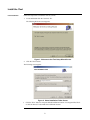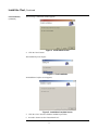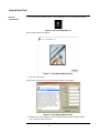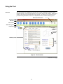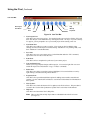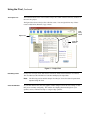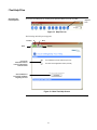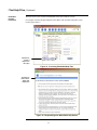
1
iTool Installation and User’s Manual
Introduction
This manual contains instructions on how to install and operate the Tyco Safety Products iTool.
The iTool is a software program designed to aid system designers in creating speaker systems that
meet the intelligibility requirements for emergency voice/alarm communications systems.
Information such as room dimensions, surface materials, ambient noise levels, and speaker types
are entered into the iTool. The software then calculates this data and provides output consisting of
room reverberation times and the estimated number of speakers for the room. Based on this
information, the iTool also estimates speaker wattages and required audio power.
Several advanced options are also available within the iTool software. Additional information can
be examined regarding Sound Pressure Levels (SPL), specific speaker locations, and detailed
reverberation specifications. The system designer can then take the output provided by the iTool
and use it to estimate a design that provides adequate audio intelligibility for an emergency
voice/alarm communications system.
The iTool is also customizable. Users can add custom surface materials (based either on mixed
compositions or absorption coefficients). Custom speaker designs can also be entered into the
iTool. Finally, if iTool is loaded on an Internet accessible computer, it is possible to perform a live
web update as new revisions become available.
IMPORTANT: The iTool is intended as an informational resource and is not
intended to provide definitive legal, engineering, design or
architectural advice. Legal, engineering, design, or architectural
requirements and interpretations may vary from jurisdiction to
jurisdiction or project to project. Therefore, no warranty or
representation is made about the sufficiency of any of the contents
of this guide. Tyco Safety Products – Westminster, disclaims any
and all liability for damages of any sort claimed to result from the
use of this guide. This guide is distributed with no warranties
whatsoever, including but not limited to, warranties of
merchantability or fitness for a particular purpose. Readers with
specific questions should consult the appropriate advisor.
In this Publication
This publication discusses the following topics:
Topic
Related Publications
See Page
Install the iTool
2
Launch the iTool
4
Using the iTool
5
iTool Help Files
8
Sample iTool Project
10
Advanced iTool Features
13
Use the “Web Up” Button to Update iTool
15
Print an iTool Project
17
Material Charts
18
Refer to the Fire Alarm Audio Applications Guide: Guideline for Designing Emergency
Voice/Alarm Communications Systems for Speech Intelligibility (579-769) for more information
on the terms and topics covered in this manual.
Tyco, Simplex, and the Simplex logo are trademarks of Tyco International Services (AG) or its affiliates in the US and/or other countries.
Copyright © 2004 Tyco Safety Products Westminster. All rights reserved.
All specifications and other information shown were current as of publication, and are subject to change without notice.
579-772
Rev. A
Install the iTool
iTool Installation
Follow the steps below to install the iTool on your PC:
1.
Locate and double-click the “itool.msi” file.
The following Welcome screen appears:
Figure 1. Welcome to the iTool Setup Wizard Screen
2.
Click the “Next” button.
The following screen appears:
Figure 2. Select Installation Folder Screen
3.
Click the “Next” button to accept the default installation location of C:\Program Files\iTool\
or click the “Browse” button and select a different location.
Continued on next page
2
Install the iTool, Continued
iTool Installation,
(continued)
The following Confirmation window appears:
Figure 3. Confirmation Screen
4.
Click the “Next” button.
The installation process begins:
Figure 4. iTool Installation
An Installation Complete screen appears:
Figure 5. Installation Complete Screen
5.
Click the “Close” button to finish the installation procedure.
6.
Proceed to the next section “Launch the iTool.”
3
Launch the iTool
Open the
iTool Software
1.
To open the iTool, double click the “Voice Intelligibility” icon on the Windows desktop:
Figure 6. Voice Intelligibility Icon
The following splash screen appears:
Figure 7. iTool Startup Splash Screen
2.
Click the “Start” button.
The first time you launch iTool, the following Registration screen appears:
Figure 8. iTool Startup Splash Screen
3.
Read the Terms and Conditions, fill in the Registration Form fields, and then click the
“Agree” button to launch the iTool.
4
Using the iTool
The iTool consists of a combination of several icons, tool bars, and pull-down menus to aid in
using the software. This section provides an overview of the iTool’s many features. Each of these
features is discussed in greater detail later in this manual. An example of a room design is also
provided in this publication to show how to implement the iTool’s features during a project:
Overview
Metric/Standard Selection
Project Title
Menu Bar
Icon Tool Bar
Status Message Bar
Project Tree
Project
Information
Buttons
Visual Aid
Window
Data Entry Fields
iTool
Data
Output
Links to Help Files
Figure 9. iTool Overview
Continued on next page
5
Using the iTool, Continued
Icon Tool Bar
New Project
Help
Save
New Room
Print
x
Web Up
Paste
Copy
Delete
Properties
Figure 10. Icon Tool Bar
New Project Icon:
Click this icon to start a new project. You can also begin a new project by clicking “File” and
then “New Project” in the Menu Bar or by clicking the “CTRL + N” keys. If you are currently
in a project, you are prompted to save your current project before starting a new one.
x
New Room Icon:
Click this icon to add a new room to a project. New rooms can also be added by right
clicking on an item in the Project Tree and selecting “Add Room” or by clicking “Edit,” and
then “Add Room” from the Menu Bar.
x
Save Icon:
Click this icon to save your current project. In the Menu Bar under the “File” command,
options also exist for “Save” and “Save As.”
x
Print Icon:
Click this icon for a comprehensive print-out of your current project.
x
Copy and Paste Icons:
Allows you to copy and paste designs within a project. You can also right click on a room
within the Project Tree and select the “Copy” or “Paste” commands.
x
Delete Icon:
Click this icon to delete a room that you have highlighted. You can also delete a room by
right clicking it, and then selecting “Delete Room.”
x
Properties Icon:
Click this icon to open Advanced Menu options for adding custom surface materials and
speakers. See the “Advanced iTool Features” section later in this manual for information on
these options.
x
Web Up Icon:
Click this icon to check the Internet for live updates to the iTool software. This procedure is
covered in the “Use the Web Up Button to Update iTool” section later in this manual.
x
Help Icon:
Click this icon to launch the iTool’s Help Files.
Note: There are also links to Help Topics that are embedded in the main iTool screen
(see Figure 9).
Continued on next page
6
Using the iTool, Continued
The Project Tree
The left-hand column of the iTool contains a Project Tree which contains a directory structure of
the rooms in a project.
The figure below shows a Project Tree with four rooms. You can right click on any of these
rooms to Add, Delete, Rename, Copy, or Paste.
Data
Entry
Fields
Project Tree
Visual Aid
Window
Figure 11. Project Tree
Data Entry Fields
For any new room you create, data must be entered into fields and selected from iTool menus.
The iTool then uses this information to calculate and display the output data.
Note:
Visual Aid Window
The following section entitled “Sample iTool Project” shows how data is inputted and
outputted using the iTool.
As you enter data into the iTool, this graphic window changes to show the wall, ceiling, or floor
that you are currently configuring. This window also displays placement designs for your
speakers, such as “minimum overlap” or “edge-to-edge” patterns.
7
iTool Help Files
Accessing the
iTool Help Files
Access the iTool Help files by clicking on the Question Mark icon in the Tool Bar.
Help File
Icon
Figure 12. Help File Icon
The following main Help screen appears:
Forward
Stop
Back
Click on the
Publication Name to
Launch a .PDF Version
of the Document
Refresh
x
iTool Installation and User’s Manual (579-772)
x
Fire Alarm Audio Applications Guide (579-769)
Click this Button to
Provide User Feedback
Regarding the iTool
Figure 13. Main iTool Help Screen
Continued on next page
8
iTool Help Files, Continued
Embedded
Help File
Information
The main iTool screen contains embedded links that lead to Help File screens.
For example, click the “Required Signal to Noise Ratio” link to launch a Help File screen
(see the figures below).
Click Here to
Launch a
Help File on
this Topic
Figure 14. Accessing Embedded Help Files
Click Here to
Return to the
Main iTool
Help Screen
Figure 15. Required Signal to Noise Ratio Help Screen
9
Sample iTool Project
Create an
iTool Project
To create a new project in iTool, follow these steps:
1.
Launch iTool by clicking the Voice Intelligibility icon on your desktop.
Metric/English
Selection
The main iTool screen appears:
Click These Fields
to Open the List of
Available Surfaces
Figure 16. iTool Overview
The new project opens with “Room 1” ready to be configured.
Note:
Refer to the Fire Alarm Audio Applications Guide: Guideline for Designing Emergency
Voice/Alarm Communications Systems for Speech Intelligibility (579-769) for detailed
descriptions of the terms and materials discussed in this section. The Applications Guide
also contains practical iTool examples (office spaces, gymnasiums, corridors etc.).
2.
From the “Unit” pull-down menu in the Icon Tool Bar select either Feet or Meters
(English or Metric).
3.
In the “Room Dimension” fields enter the Length, Width, and Height of Room 1.
4.
Below the Room Dimension fields are a series of menus for the floor, ceiling, and walls of
Room 1. Click each field and select the proper surface materials (wood, concrete, drapery, etc.).
Note: See the “Material Charts” section later in this manual for more information on the
various material selections contained in the iTool.
5.
From the “Speaker” pull-down menu, select the specific speaker brand and mounting type
(wall or ceiling) to use for this project.
6.
From the “Placement” pull-down menu, select the preferred speaker layout (edge-to-edge,
minimum overlap, or full overlap).
Note: Refer to the Visual Aid window in the upper-right corner of the iTool while making
your Placement selection.
7.
Enter the appropriate data into the Listener Height, Ambient Noise, and Required Signal to
Ambient Noise Ratio fields. (5, 55, and 15 are the respective defaults as shown above).
Continued on next page
10
Sample iTool Project, Continued
Create an
iTool Project,
(continued)
8.
Click the “Calculate” button and output data appears in the fields located on the bottom-right
of the iTool window:
Project
Information
Buttons
iTool
Output
Data
Figure 17. iTool Overview
In the Room 1 sample shown above, the iTool has determined the room has a Reverberation Time
of 0.4 seconds. The room is estimated to require 24 speakers at 0.25 Watts each, for a total of
6 Watts of audio power.
Three additional project information buttons allow you to further analyze Room 1.
9.
Click the “Speaker Location” button to view a plot of speaker locations for Room 1 (Figure 18).
10. Drag the magnifying glass cursor over any of the individual speaker plots and click to zoom
in on a particular speaker (Figure 19). Row and column spacing are provided.
Speaker
Location
Button
Note:
Click anywhere on the plot in Figure 19 to return to the previous view in Figure 18.
Figure 18. Speaker Location Guide
Figure 19. Close-up of Speaker Plot
Continued on next page
11
Sample iTool Project, Continued
Create an
iTool Project,
(continued)
11. Click the “SPL Distribution” button.
SPL Distribution Button
X and Y
Coordinates
with SPL
Reading
Resolution
Slide Bar
dB Legend
SPL91
SPL89
SPL86
Figure 20. SPL Distribution Screen
The screen above shows how Sound Pressure Levels (SPL) are distributed throughout Room 1.
An on-screen cursor allows you to pinpoint the SPL for X and Y coordinates in the room.
A Resolution Slide Bar is also available to adjust the detail level of the SPL image shown.
In Figure 20, the darker center of the screen shows an SPL of 91. The lighter circle surrounding
the center, has an SPL of 89 and the corners have an SPL of 86.
Note:
Refer to the color-coded “Legend (dB)” (shown on the left side of the figure above) to
measure the corresponding colored SPL displayed for Room 1.
12. Click the “Reverberation Time” button.
Reverberation
Time
Button
The following screen appears:
Figure 21. SPL Distribution Screen
This screen provides further analysis on both reverberation time results and speaker coverage
information. Specifications include more SPL details and specific reverberation times at various
frequencies.
12
Advanced iTool Features
Advanced
Menu Options
You can customize the iTool by programming custom surface materials and/or speakers. These
commands can be accessed by either clicking the “Properties” icon from the Icon Tool Bar or by
clicking “Options,” “Add New Surface Material” or “Add New Speaker” from the Menu Bar.
Properties
Figure 22. Selecting Advanced Features
Add a New
Surface Material
Note:
If you choose to add a new surface material, a screen similar to the following appears:
Refer to the “Material
Charts” section later in
this document for
absorption coefficients
and more information on
surface materials.
Figure 23. Add Custom Surface Material Screen
1.
Select either the “I want to add a new surface material by entering absorption coefficients” or
the “I want to add a new mixed composition surface” radio button.
a.
Absorption coefficients: Choose this option to create a unique surface material that is
not currently contained in the iTool.
1. Type in a name of your material in the “Surface Material Name” field.
2. Enter in the absorption coefficients in the Hz and kHz fields.
3. Click the “Add” button and then click “OK.”
The new material name now appears as a valid option within the iTool’s floor, ceiling, and
wall pull-down menus.
b. Mixed Composition Surface: Choose this option if you have a surface composed of
more than one existing iTool material. For example, a gypsum wall containing glass
windows.
1.
2.
3.
Select pre-existing materials from the Surface Material fields.
For each selection, enter the Square Feet (or Meters) of material.
Click the “Add” button and then click “OK.”
The absorption coefficients for the material are automatically calculated and appear.
The new material name now appears as a valid option within the iTool’s floor, ceiling, and
wall pull-down menus.
Continued on next page
13
Advanced iTool Features, Continued
Delete a
Surface Material
Follow these steps to delete an existing custom surface material:
1.
Select an existing custom material from the “Surface Material Name” pull-down menu.
2.
Click the “Delete” button and then the “OK” button in the confirmation window.
This material is no longer shown in the iTool’s pull down menus.
Add a
Custom Speaker
Follow these steps to add a custom speaker to the iTool’s speaker list:
1.
From the iTool’s Menu Bar, click “Options,” and then “Add Custom Speaker.”
The following screen appears:
Figure 24. Add Custom Speaker Screen
2.
Enter a name for the new speaker in the “Custom Speaker Name” field.
3.
Enter a dB rating in the “Sensitivity” field.
4.
Enter an angle (in degrees), in the “2kHz – 6dB Coverage Angle as Projected onto listener
plane” field.
5.
Enter the distance for the coverage angle in the “At Distance” field. Then select Feet or
Meters from the pull-down menu.
6.
Select either “Ceiling Mount” or “Wall Mount” from the “Speaker Type” pull-down menu.
7.
Enter the proper power tap information (in Watts) into the “Power Taps (W)” field.
8.
Click the “Add” button, and then the “OK” button.
This custom speaker now appears with the other pre-existing speakers as a valid option within
the iTool’s “Speaker” pull-down menu.
Delete a
Custom Speaker
Follow these steps to delete an existing custom speaker:
1.
Select an existing speaker from the “Custom Speaker Name” pull-down menu.
2.
Click the “Delete” button and then the “OK” button in the confirmation window.
This speaker is no longer shown in the data entry pull-down menus.
14
Use the “Web Up” Button to Update iTool
Updating the iTool
If iTool is loaded on an Internet accessible computer, the software notifies you when new updates
are available for download. When you launch iTool and the following message appears (as shown
below), you can click on the “Web Up” button in the iTool Menu Bar to download the update:
“Web Up”
Button
This popup
indicates an
update is ready
for download
Figure 25. Web Update Screen
1.
When the “New Updates Ready to Download” message appears, click the “Web Up” button
from the Menu Bar.
A screen similar to the following appears:
Figure 26. Web Update Utility Screen
2.
Review the releases available. Release Dates, Versions, File Size, and Update Status are
provided.
3.
Check the boxes of files you want to download, and then click the “Update” button.
Continued on next page
15
Use the “Web Up” Button to Update iTool, Continued
Updating the iTool,
(continued)
A screen similar to the following appears:
Figure 27. Web Update Utility Screen
The status for the updates changes to read “File is updated successfully.”
4.
Click the “Exit” button to return to the main iTool screen.
16
Print an iTool Project
Print an
iTool Project
1.
Click the “Print” icon from the Tool Bar or “File,” and then “Print” from the menu bar.
A Print Preview screen similar to the one below appears.
2.
If your project contains multiple rooms, use the “Previous” and “Next” buttons at the top of
the page to toggle selections from room to room.
3.
Click the “Print” button.
Toggle Rooms with the “Previous” and “Next” buttons
Figure 28. Print Preview Screen
17
Material Charts
Materials
The table below contains absorption coefficients of some common materials. The coefficients are
listed at particular frequencies. Some materials absorb sound more effectively at higher
frequencies, others at lower frequencies. Some materials, like smooth concrete/terrazzo absorb
very little sound at any frequency. The user defined surfaces can be used to enter new materials,
like a special type of acoustic treatment, or can be used to define surfaces of mixed composition as
described in the next section.
Use the table below to define surface characteristics for the iTool. Enter specifications from
manufacturers data sheets or create surfaces that are a mixture of materials. The coefficients are in
the range of 0.01 to 1.00, where a larger number indicates a higher level of absorption.
Table 1. Materials Absorption Coefficient Data Table
No.
125 Hz
250 Hz
500 Hz
1 kHz
2 kHz
1
Carpet: Indoor/Outdoor on Concrete
Material
0.01
0.05
0.10
0.20
0.44
4 kHz
0.64
2
Carpet: Medium on Foam Rubber
0.10
0.15
0.40
0.60
0.75
0.75
3
Carpet: Heavy on Foam Rubber
0.08
0.23
0.56
0.68
0.70
0.73
4
Carpet: Heavy Pile on Concrete
0.02
0.06
0.14
0.36
0.60
0.64
5
Carpet: Medium Pile on Concrete
0.03
0.05
0.15
0.30
0.44
0.55
6
Carpet: Thin Pile on Concrete
0.04
0.05
0.10
0.20
0.44
0.64
7
Wood Parquet Floor
0.04
0.04
0.07
0.06
0.06
0.07
8
Linoleum on Concrete
0.02
0.03
0.03
0.03
0.03
0.02
9
Marble or Glazed Tile
0.01
0.01
0.01
0.01
0.02
0.02
10
Concrete Block – Rough, unpainted
0.36
0.44
0.31
0.29
0.39
0.25
11
Concrete or Terrazzo
0.01
0.01
0.01
0.01
0.02
0.02
12
Gypsum over 2 x 4 – 16 o.c.
0.29
0.10
0.05
0.04
0.07
0.09
13
Linear Wood
0.43
0.50
0.36
0.44
0.33
0.27
14
Linear Wood w/1” Fiberglass
0.67
0.79
0.75
0.80
0.50
0.38
15
Linear Wood w/2” Fiberglass
0.79
0.86
0.98
0.87
0.58
0.49
16
Drapery (10oz/yd velour-flat)
0.04
0.05
0.11
0.18
0.30
0.35
17
Drapery (14oz/yd velour-flat)
0.05
0.07
0.13
0.22
0.32
0.35
18
Drapery (14oz/yd, 50%, draped)
0.07
0.31
0.49
0.75
0.70
0.60
19
Drapery (18oz/yd velour-flat)
0.05
0.12
0.35
0.48
0.38
0.36
20
Drapery (18oz/yd, 50% draped)
0.14
0.35
0.53
0.75
0.70
0.60
21
Brick Unglazed
0.03
0.03
0.03
0.04
0.05
0.07
22
Glass
0.35
0.25
0.18
0.12
0.07
0.04
23
Partition – Accordion
0.33
0.20
0.15
0.10
0.05
0.05
24
Plywood Paneling, 0.375”
0.28
0.21
0.17
0.09
0.10
0.10
25
Plywood Paneling, 0.75”
0.10
0.10
0.10
0.08
0.08
0.10
26
Armstrong 1.5” Silok Ceiling Tile
0.36
0.43
0.86
0.99
0.99
0.98
27
Armstrong Lay-in Ceiling Tile 5/8”
0.28
0.50
0.70
0.70
0.70
0.70
28
Tectum 1” Acoustic Ceiling Tile
0.44
0.43
0.30
0.41
0.56
0.79
29
Tectum 1.5” Acoustic Ceiling Tile
0.43
0.43
0.33
0.49
0.66
0.76
30
Tectum 2” Acoustic Ceiling Tile
0.47
0.46
0.36
0.55
0.74
0.79
31
User Defined Surface #1
32
User Defined Surface #2
33
User Defined Surface #3
34
User Defined Surface #4
35
User Defined Surface #5
36
User Defined Surface #6
Continued on next page
18
Material Charts, Continued
Creating Surfaces of
Mixed Compositions
The surfaces listed in Table 1 are for a single composition, (i.e. walls are all gypsum or all glass,
etc.). For surfaces of mixed materials it is necessary to combine absorption coefficients, such as a
wall with windows. This is a fairly simple procedure of calculating the absorption for each
material individually based on the surface area it occupies, and then dividing by the total area of
the surface.
As an example, take a 40-foot x10-foot gypsum wall with four 2.75-foot x 4-foot windows.
The total surface area is 400 ft² with 44 ft² of windows and 366 ft² of gypsum wall.
Figure 29. 40-foot x 10-foot Wall with Windows
Follow these steps to calculate the absorption for the mixed wall:
1.
Multiply the absorption coefficient at each frequency by the surface area.
2.
Add the total absorption for each material.
3.
Divide by the total surface area.
4.
Enter these absorption coefficients (the sample shown in the bottom shaded row of Table 2)
into the “Absorption Coefficient” fields of iTool’s “Add Custom Surface Material” screen
(see Figure 23).
Table 2. Surface with Multiple Materials
Surface
125 Hz
250 Hz
500 Hz
1 kHz
2 kHz
4 kHz
Glass
0.35
0.25
0.18
0.12
0.07
0.04
Glass Surface Area = 44 Square Feet
x44
x44
x44
x44
x44
x44
Total Glass Absorption
15.4
11.0
7.9
5.3
3.1
1.8
Gypsum over 2 x 4 – 16-inches o.c.
0.29
0.10
0.05
0.04
0.07
0.09
Wall Surface Area = 366 Square Feet
x366
x366
x366
x366
x366
x366
Total Gypsum Wall Absorption
106.1
36.6
18.3
14.6
25.6
32.9
Total Absorption for Entire Wall
121.5
47.6
26.2
19.9
28.7
34.7
Wall Surface Area = 400 Square Feet
/ 400
/ 400
/ 400
/ 400
/ 400
/ 400
Average Absorption Coefficient for
Wall with Windows
0.30
0.12
0.07
0.05
0.07
0.09
19
579-772
Rev. A