1
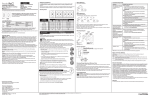
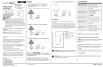
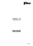
MDKC-1 (issue-1)
MIDI Draw Knob Controller
User Manual Version 1.2
Firmware - V1.4
©2010 Artisan Classic Organ
All rights reserved
LIMITED WARRANTY
Classic Organ Works warrants the MDKC-1 to be free from defects in
materials and workmanship under normal use for a period of ONE YEAR from
the delivery date. This warranty applies only if the product is owned by the
original purchaser who has the bill of sale.
This warranty explicitly excludes any cables provided with the MDKC-1 which
may become defective as a result of normal wear and tear.
In the event of a defect in materials or workmanship, please contact Classic
Organ Works immediately. In particular, defects due to shipping should be
reported within 15 days for insurance claim purposes. For all other defects,
Classic Organ Works agrees to repair or replace all defective parts of said
products which are returned, transportation prepaid, for inspection at its service
centre within the period of the warranty.
In the event that Classic Organ Works determines the product requires repair
because of user misuse or regular wear, it will assess a fair repair or
replacement fee. The customer will have the option to pay this fee and have the
unit repaired and returned, or not pay this fee and have the unit returned unrepaired.
Classic Organ Works will not be liable for consequential, special, indirect, or
similar damages or claims including loss of profit or any other commercial
damage, and in no event will Classic Organ Works’ liability for any damages to
the purchaser or any other person exceed the price paid for the product,
regardless of any form of the claim. Classic Organ Works specifically disclaims
all other warranties, expressed or implied. Specifically, Classic Organ Works
makes no warranty that the product is fit for any particular purpose.
This warranty shall be interpreted, and governed by applicable laws in the
province of Ontario, Canada. If any provision of this warranty is found void,
invalid or unenforceable, it will not affect the validity of the balance of the
warranty, which shall remain valid and enforceable according to its terms. In
the event any remedy hereunder is determined to have failed of its essential
purpose, all limitations of liability and exclusion of damages set forth herein
shall remain in full force and effect.
MDKC-1 Manual 1.2.doc
2
General Description
MDKC-1 Manual 1.2.doc
3
The MDKC MIDI Drawknob Controller board is a unit that can control up to
48 dual-magnetic stops. Stops may be drawknobs, tongue tabs or tilt-tabs
(rockers). The controller board generates a MIDI signal from the stop switches
for the purposes of controlling an organ using Hauptwerk as the control for the
system or a Classic Organ Works Linux-based organ control system.
The MDKC accepts two standard Classic OUTN-1 negative driver boards that
can handle 24 stops each. The board contains an input shift register for the
combined switches and all the necessary controls for supported user interfaces
(USB, MIDI, etc.) The switch addressing creates up to 48 Note-On messages that
are sent on one MIDI channel.
Each stop is plugged into the MDKC via a four-pin connector. This makes it
easy to re-arrange the stop order or to cross-plug them to locate stop faults.
The On and Off stop coils are each driven with a pulse length of typically 250
milli-sec. When not being activated, the entire unit takes only a few milli-Amps
of current. Furthermore, if stops are commanded to move but are already in the
proper position (as determined by the stop switch), they are not activated, thus
saving power.
By using the available Test/Calibrate mode, the optimum pulse duration will
be set for each stop. Omitted stops are ignored.
An OUTT-1 LED board may be plugged into the MDKC for additional output
checks, while the OUTN-1 boards are in place. Plug the OUTT-1 LED boards into
the underside of the MDKC to attain this.
The 48 stop-coil actions use data returned from the controlled system as a
MIDI-format signal on the same channel as the switches and use the same codes
as the switches. The MIDI IN and OUT connectors allow another MIDI device such
as a CMK keyboard to also control the computer.
The MDKC also monitors Hauptwerk’s status to ensure that the drawknobs
or tabs accurately represent the state of the switches on-screen. If you hand
register a stop on-screen, the MDKC will also physically move the stop tab.
MIDI/USB
The USB cable is the only option for connecting the MDKC to the computer.
The MDKC functions as a MIDI/USB interface. So you do not have to purchase a
separate MIDI interface to use the MDKC.
The MIDI IN and OUT on the MDKC are used only if you wish to connect
another MIDI device, such as a CMK keyboard or MIDI pedalboard to the
computer.
MDKC-1 Manual 1.2.doc
4
STEP 1: MOUNTING
Mounting holes are provided for eight #4 screws that pass through swaged
non-threaded spacers to space the board up from the mounting surface.
There are 9 spacers in order to prevent the board from flexing unduly as
stops or boards are plugged/unplugged.
These spacers also protect the various pins that project beneath the board.
While these pins are not normally used, they can be used to operate an OUTT-1
LED test board. The MDKC board should be mounted reasonably close to the
stops so that all connections can be easily made. It is not necessary to provide
ventilation as the board consumes little power.
STEP 2: CONNECTING POWER TO THE MDKC-1
AND DRIVER BOARDS
Power
No power is necessary other than the console switched +12V. However, this
should be capable of driving all stops simultaneously – typically a peak current
of 0.5 Amp per stop.
There are two terminal blocks on the MDKC because the total peak current
could be as high as 24 Amps, which exceeds the current capacity of normal
terminal strips. Each terminal block is independently fused at 6 Amps
continuous (12 Amps Peak).
In order not to cause undue voltage drops, each of these terminals should be
wired independently and directly to the power supply.
DO NOT simply parallel them into one thick wire or loop from one to the
other. Each has two pins for each rail voltage to allow two thinner wires to be
used. (The two inputs are dioded together to run the logic circuitry on the board
that takes only a small current).
If only one driver board is installed, then only one power terminal should be
hooked-up, use the power terminal on the same side as the installed driver
board. If both driver boards are installed, then hook-up both power terminals.
MDKC-1 Manual 1.2.doc
5
STEP 3: SET THE MDKC-1 BOARD NUMBER
Output Boards
Two standard OUTN-1 driver boards can be plugged into the MDKC if up to
48 stops are to be controlled. One driver board will control up to 24 stops.
When plugging in an OUTN-1 board, be sure that its LED (if fitted) between
connectors is aligned with the hole in the MDKC board. Make sure that Link -1
on the OUTN-1 board is set to ‘E’.
The link on the MDKC board (LK1) must be set to (48) whether there is one
or two OUTN driver boards installed.
24
LK1
48
Three MDKC boards can be used at the same time for a maximum of 128
stops.
For each MDKC board, set DIP Switch 5, 6, 7 to select the Hauptwerk version
and board number as follows:
Switch-8
Switch-7
Switch-6
Switch-5
n/u
Off
Off
Off
n/u
Off
Off
On
n/u
Off
On
Off
n/u
On
Off
Off
n/u
On
Off
On
n/u
On
On
Off
MDKC-1 Manual 1.2.doc
6
Hauptwerk
Version
Hauptwerk 3 Bank 0
(00H-2FH) (stops 1-48)
Hauptwerk 3 Bank 1
(30H-5FH) (stops 49-96)
Hauptwerk 3 Bank 2
(60H-7FH) (stops 97-128)
Hauptwerk 4 Bank 0
(00H-2FH) (stops 1-48)
Hauptwerk 4 Bank 1
(30H-5FH) (stops 49-96)
Hauptwerk 4 Bank 2
(30H-5FH) (stops 97-128)
Board
#
1
2
3
1
2
3
STEP 4: WIRE THE DRAWKNOBS TO THE
MDKC-1
Stops
Each stop should be wired to a four-pin socket that plugs into the board in one
of 48 places. The connection contains the Stop Switch to pin-1, Common +12V
to pin-2, Off Coil to pin-3, On Coil to pin-4 . There is no harm in moving these
while the power is on. The recommended cable connectors are polarized to
prevent reversed plugging. Pin-1 (for the switch) is nearest the edge of the
board. Insulation-displacement connectors are preferred as the wires do not
need to be stripped.
Make
(MDKC Pin)
Klann DK56 Drawknob
Harris Drawknob, 5-pin, Std.
Harris Drawknob, 5-pin, Classic
Harris Tilt-tab, 5-pin
Harris Drawknob, 9-pin, Std.
Harris Drawknob, 9-pin, Classic
Harris Tilt-tab, 9-pin, Std.
Kimber-Allen Drawknob, 7-pin
OSI Tilt-tab, 8-pin
Peterson Drawknob, 8-pin
Peterson Tilt-tab, 8-pin
Syndyne Drawknob, 6-pin
Syndyne Tilt Tab, 8-pin
Switch
(Brown 1)
1
5
4
5
9
7
9
5
8
8
8
3
6
+12V
Common
(Red 2)
2, 5
3
3, 5
3
5, 6
5, 6, 9
5, 6
3, 4
1, 7
1, 6
1, 6
1, 4
1, 8
Common Draw Knob Schematics
MDKC-1 Manual 1.2.doc
7
Off Coil
(Orange 3)
On Coil
(Yellow 4)
4
1
1
1
1, 2
1, 2
1, 2
1
5
5
5
5
5
3
2
2
2
3
3
3
2
3
3
3
2
3
Not Used
Remarks
Join 2 to 5
4
4
4, 7, 8
4, 8
4, 7, 8
6, 7
4, 6
2, 4, 7
2, 4, 7
6
2, 4, 7
Join 3 to 5
Needs 0V to pin-4
Join 5, 6, 9
Needs 0V to pin-7
Join 3, 4
Join 1 to 7
Join 1 to 6
Join 1 to 6
Join 1 to 4
Join 1 to 8
MDKC-1 Manual 1.2.doc
8
MDKC-1 Manual 1.2.doc
9
MDKC-1 Connector
MDKC-1 Manual 1.2.doc
10
STEP 5: SET THE MIDI CHANNEL
Note: For safety, make sure the power is Off any time you make changes to
the dip switches.
Channel Selection
On the eight-position DIP-Switch, switches 1-4 select the MIDI Channel as
follows:
Channel Channel Switch-4 Switch-3 Switch-2 Switch-1
(Binary) Number
0
1
Off
Off
Off
Off
1
2
Off
Off
Off
On
2
3
Off
Off
On
Off
3
4
Off
Off
On
On
4
5
Off
On
Off
Off
5
6
Off
On
Off
On
6
7
Off
On
On
Off
7
8
Off
On
On
On
8
9
On
Off
Off
Off
9
10
On
Off
Off
On
10
11
On
Off
On
Off
11
12
On
Off
On
On
12
13
On
On
Off
Off
13
14
On
On
Off
On
14
15
On
On
On
Off
15
16
On
On
On
On
Remarks
Default
Note that the required number is greater by one than the actual MIDI channel
binary code (as indicated by the switch positions). Switch-1 is nearest to the
centre of the board.
If the DIP-Switch is changed to select a different MIDI channel, this will take
effect immediately. However, for safety’s sake, please turn off the power when
making changes to the DIP-Switches.
A flashing green ‘Heartbeat ’LED indicates that the board is in normal
operating mode, and has been Calibrated.
MDKC-1 Manual 1.2.doc
11
STEP 6: CONNECT THE USB CABLE
Connect the USB cable to your computer.
The USB cable may or may not be connected to the MDKC when in Calibrate
mode, Calibrate will work either way.
The USB cable must be connected to the MDKC to configure or use
Hauptwerk.
STEP 7: CALIBRATE THE DRIVER BOARD AND
DRAWKNOBS
Explaining the Process
The Test/Calibrate mode, first pulses all the stops On. After a 5 second
pause to allow manual operation of a non-moving stop, it pulses them all Off.
If some associated stop magnets do not operate, there may be a problem
with their magnets or with the source driving the magnets. If a switch is not
operating (e.g., is Off all the time) the stop will move On but not Off.
Conversely, if the switch is On all the time, the stop can go Off but will not go
On. This could mean that the switch needs adjustment or is perhaps not
connected or shorted. It could also mean that the stop connector is reversed.
Under these conditions, the MDKC will vary the pulses to the coils either by
altering their duration or by repeating them. It then stores the new values. After
several tries, if the stop does not respond, the system abandons it, leaving the
original values. Thus absent stops are ignored. Stops that work in one direction
only will be correctly set for that direction. When fixed for the other direction,
simply re-calibrate.
To Calibrate:
1. Turn Off the power to the MDKC and the stops
2. Check to make sure all of your draw knobs are connected to the MDKC
properly
3. Turn DIP-Switch 5 and 6 “On”
4. Turn On the power to the MDKC and draw knobs
5. The LED heartbeat light will be solid On for approximately 4 seconds at
start of Calibrate
6. The LED will turn Off when Calibrating
7. The MDKC will turn all stops Off
8. All stops will then turn On
9. There is a pause for about 5 seconds
10. All stops will then turn Off again and calibration is complete
MDKC-1 Manual 1.2.doc
12
11. The heartbeat light will be solid On
12. Turn Off power to the MDKC and the stops
13. To Calibrate again, go to step 4 of the Calibrate procedure
or
14. Turn DIP-Switch 5 and 6 back to “Off”
Switch-8
Switch-7
Switch-6
Switch-5
Remarks
n/u
Off
On
On
Calibrate Drawknob
Function
LED
Remarks
Calibrate Mode
On
Calibrate Mode
Off
For approximately 4 second at start
of Calibrate
During Calibrate
Calibrate Mode
On
When Calibrate is finished
Diagnoses without using the Test Mode:
Polarized four-pin stop headers are used. If a stop connection is reversed by
mis-wiring the header in reverse, the following will be noticed:
1. The switch will effectively be On (through both coils in series).
2. The Off coil may be continuously energized but only if the OUTN-1 Off
output is turned On. There should be little or no physical resistance to
manually turning On the stop.
3. Turning the stop On manually will have no effect. All it does is to apply
the +12V to the On output of the OUTN-1 but that is not normally turned
On.
A first test is to have the organ powered with all stops Off while plugging in
the stop connectors. No stop on the organ should turn On. If it does, it indicates
that the stop switch is On, possibly via both coils in series due to a reversed
stop connector.
Another check is to move all stops to the On position before applying the
power. Any that move off might be mis-plugged and should be checked
immediately.
If the Test-Mode indicates that the Off coil works but that the switch is stuck
On, it is possible that the stop connector is reversed.
If the system controls each stop satisfactorily but they do not move properly
at the same time under normal conditions when all may be required to move,
such as a General Cancel, the likely cause is that the power supply has
insufficient reserve. It needs to be able to supply typically a ½-Amp per stop. A
regulated supply is best but an unregulated one will be alright if a large
capacitor is used as a reservoir.
MDKC-1 Manual 1.2.doc
13
STEP 8: CONFIGURING HAUPTWERK II & III TO
WORK WITH YOUR MDKC-1
Overview
The MDKC generates and sends MIDI Control Messages. It also receives
Switch Output controller messages from Hauptwerk.
You need to configure Hauptwerk II and III to look for and send both kinds
of messages. Hauptwerk IV will have a “MIDI Learn” feature that will make this
process much easier.
Switch messages are the messages that will trigger events (i.e. turning stops
On and Off) in Hauptwerk.
MIDI Input Paths
Connect the MDKC Switch Messages by going to General Settings>List
Switch (MIDI) Inputs in Hauptwerk.
We created a new input path Called “Classic Draw Knobs” and set it on MIDI
channel 16.
Select the device that corresponds with the MDKC under the MIDI Input Port.
MDKC-1 Manual 1.2.doc
14
MIDI Output Paths
You also need to configure Hauptwerk’s MIDI output to communicate back to
the MDKC. Go to Organ Settings>Configure MIDI Output Paths.
Create an Alias called “Classic Draw Knob Out” by clicking on “Insert”
Make sure it is set on the same channel you set the MDKC on in the MIDI
Input Paths. Here we chose to set MIDI channel to 16 and the MIDI Output Port
to select the MDKC.
Switch MIDI Input Paths (under General Settings)
These examples show that we created space for 1 - 32 draw knobs. They are
simply numbered 1 -32. You may, instead, wish to organize them according to
entries that already exist in the list or make names that correspond with
whatever the engraving reads.
The whole idea in the naming process is to make it easy to identify which
physical switch you are referring to when it comes time to match that switch
with an on-screen switch.
MDKC-1 Manual 1.2.doc
15
Message Sent When Engaging
• Set Event type to “MIDI control change (with specific controller value)”
• Set MIDI input path to the channel you specified in the MIDI input path
section. Here, we have used channel 16.
• Set Event value to a number of one less than what the number of the MDKC
pin. So if the pin is number 1, make the Event value 0. If the pin number is 32,
make the Event value 31.
• If you have strung 2 MDKC together and have made output pin 48 send
represent 96, make the Event number 95.
MDKC-1 Manual 1.2.doc
16
Message Sent When Disengaging
• Set all the values to be the same as in the “message sent when engaging”
section except for the “Event value”
• Set the Event value to “80”
Here is a similar example for pin 32 of the MDKC. Notice the similarities and
that only the Event value is different.
List Switch MIDI Outputs
The settings in “List Switch MIDI Outputs” are almost identical to those of the
inputs section.
The settings for pins 1 and 32 are below.
• Set Event type to “MIDI control change (with specific controller value)”
• Set MIDI input path to the channel you specified in the MIDI input path
section. Here, we have used channel 16.
• Set Event value to a number of one less than what the number of the MDKC
pin. So if the pin is number 1, make the Event value 0. If the pin number is 32,
make the Event value 31.
If you have strung 2 MDKC together and have made output pin 48 send
represent 96, make the Event number 95.
MDKC-1 Manual 1.2.doc
17
MDKC-1 Manual 1.2.doc
18
Connect Switch (MIDI) Inputs to Organ Switches
Now you can connect the on-screen switches to the hardware switches.
Pick a stop or switch on the right and then pick the name of the hardware
switch (i.e. tab or draw knob) that you want to control it.
This is where it becomes important to have named each tab or draw knob that
you can easily identify.
Again you will see pin 1 and 32 represented.
Once you have picked a couple of stops, click “OK” and try them out.
MDKC-1 Manual 1.2.doc
19
APPENDIX A: HOW TO LOAD AND CONFIGURE
THE MDKC FOR FIRMWARE UPDATES
From time to time software updates for the MDKC may be available, this
section provides the instruction on how to load the new software onto the MDKC
and configure the DIP Switches.
**Available for PC computers only.
1. You will receive an e-mail from Classic MIDIWorks with a file attachment in
the format xxx.hex. Save this file somewhere on your computer where you
will be able to find it easily
2. With the power for the MDKC turned Off, connect the USB cable (see Step 6)
3. Turn DIPSW 5, 6, 7 On
4. Plug in/Turn On the MDKC, the Green LED will Flash approximately 2 times
the speed of normal mode
5. On your computer start the program "MDKC Boot Loader"
6. Click on the 'Open Hex File' box and select the file you have received
7. Click on 'Program/Verify'. This will load the new .hex file onto the MDKC
8. Shut down “MDKC Boot Loader”
9. Turn power Off on the MDKC
10. Turn DIPSW 5, 6, 7 Off
11. Follow the instructions for Drawknob Calibration (see Step 7)
Switch-8
Switch-7
Switch-6
Switch-5
Remarks
n/u
On
On
On
Firmware Update
Function
LED
Remarks
Firmware Update
Rapid
Flashing
During firmware update LED
flashes approximately twice as fast
as in normal operating mode
MDKC-1 Manual 1.2.doc
20
APPENDIX B: DIP SWITCH SETTINGS
Channel Channel Switch-4 Switch-3 Switch-2 Switch-1
(Binary) Number
0
1
Off
Off
Off
Off
1
2
Off
Off
Off
On
2
3
Off
Off
On
Off
3
4
Off
Off
On
On
4
5
Off
On
Off
Off
5
6
Off
On
Off
On
6
7
Off
On
On
Off
7
8
Off
On
On
On
8
9
On
Off
Off
Off
9
10
On
Off
Off
On
10
11
On
Off
On
Off
11
12
On
Off
On
On
12
13
On
On
Off
Off
13
14
On
On
Off
On
14
15
On
On
On
Off
15
16
On
On
On
On
Remarks
Switch-8
Switch-7
Switch-6
Switch-5
n/u
Off
Off
Off
n/u
Off
Off
On
n/u
Off
On
Off
n/u
On
Off
Off
n/u
On
Off
On
n/u
On
On
Off
Switch-8
Switch-7
Switch-6
Switch-5
Remarks
n/u
Off
On
On
Calibrate Drawknob
n/u
On
On
On
Firmware Update
MDKC-1 Manual 1.2.doc
21
Default
Hauptwerk
Version
Hauptwerk 3 Bank 0
(00H-2FH) (stops 1-48)
Hauptwerk 3 Bank 1
(30H-5FH) (stops 49-96)
Hauptwerk 3 Bank 2
(60H-7FH) (stops 97-128)
Hauptwerk 4 Bank 0
(00H-2FH) (stops 1-48)
Hauptwerk 4 Bank 1
(30H-5FH) (stops 49-96)
Hauptwerk 4 Bank 2
(30H-5FH) (stops 97-128)
Board
#
1
2
3
1
2
3
APPENDIX C: LED STATUS
Function
LED
Remarks
New MDKC
or
New PIC chip
or
New Firmware Update
Calibrate Mode
On
During operating mode before
Calibrate
On
Calibrate Mode
Off
For approximately 4 second at start
of Calibrate
During Calibrate
Calibrate Mode
On
When Calibrate is finished
Firmware Update
Rapid
Flashing
Normal Operating
Mode
Flashing
During firmware update LED
flashes approximately twice as fast
as in normal operating mode
After MDKC has been Calibrated
the LED flashes On/Off once,
approximately every 1 second
MDKC-1 Manual 1.2.doc
22