1
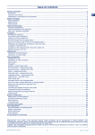
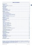
TABLE OF CONTENTS
General information. ................................................................................................................................................................... 2
Introduction. ................................................................................................................................................................................ 2
Purpose of the manual. ............................................................................................................................................................... 2
Identification of manufacturer and equipment. ............................................................................................................................ 2
Safety information. ...................................................................................................................................................................... 3
Safety regulations. ...................................................................................................................................................................... 3
Safety devices. ............................................................................................................................................................................ 4
Safety signals. ............................................................................................................................................................................. 4
Technical information. ................................................................................................................................................................ 5
Technical specifications............................................................................................................................................................... 5
General description of the appliance........................................................................................................................................... 6
Main parts. .................................................................................................................................................................................. 7
Installation.................................................................................................................................................................................... 8
Packing and unpacking. .............................................................................................................................................................. 8
Planning of system installation. ................................................................................................................................................... 8
Setting up of the perimeter wire. ................................................................................................................................................. 9
Re-entry method to the charging station. .................................................................................................................................. 10
Setup of the robot’s quick re-entry to the charging station. ....................................................................................................... 10
Preparation and marking the boundaries of the work areas. .....................................................................................................11
Installation of perimeter wire. .................................................................................................................................................... 14
Installation of the charging station and power supply unit......................................................................................................... 16
Battery charging on first use. .................................................................................................................................................... 17
Adjustments. .............................................................................................................................................................................. 17
Adjustment recommendations................................................................................................................................................... 17
Adjustment of cutting height. ..................................................................................................................................................... 17
Use and operation. .................................................................................................................................................................... 18
Recommendations for use. ....................................................................................................................................................... 18
Description of robot commands. ............................................................................................................................................... 18
Menu access. ............................................................................................................................................................................ 18
Navigation. ................................................................................................................................................................................ 18
Settings – programming mode. ................................................................................................................................................. 20
Work schedules – programming mode. .................................................................................................................................... 21
Secondary areas – programming mode. ................................................................................................................................... 22
Safety – programming mode. .................................................................................................................................................... 22
Operating mode – programming mode. .................................................................................................................................... 23
Language options – programming mode. ................................................................................................................................. 23
Initial start up – automatic mode. .............................................................................................................................................. 23
Robot safety stop. ..................................................................................................................................................................... 24
Automatic return to the charging station. .................................................................................................................................. 24
Use of the robot in closed areas with no charging station......................................................................................................... 24
Starting the robot without the perimeter wire. ........................................................................................................................... 25
Password entry.......................................................................................................................................................................... 25
Visualising the display during the work phase. ......................................................................................................................... 26
Prolonged inactivity and restarting. ........................................................................................................................................... 26
Battery charging after prolonged inactivity. ............................................................................................................................... 27
Operating tips. ........................................................................................................................................................................... 27
Routine maintenance. ............................................................................................................................................................... 28
Maintenance recommandations. ............................................................................................................................................... 28
Scheduled maintenance table. .................................................................................................................................................. 28
Robot cleaning. ......................................................................................................................................................................... 28
Troubleshooting. ....................................................................................................................................................................... 29
Troubleshooting guide. ............................................................................................................................................................. 29
Part replacement. ...................................................................................................................................................................... 31
Recommendations for replacing parts. ..................................................................................................................................... 31
Battery replacement. ................................................................................................................................................................. 31
Blade replacement. ................................................................................................................................................................... 32
Robot disposal. ......................................................................................................................................................................... 32
EC declaration of conformity.................................................................................................................................................... 32
Reproduction, even partial, of this document without written permission by the manufacturer is strictly forbidden. The manufacturer assumes a policy of continual improvement and reserves the right to modify this document without
prior notice on condition that the changes do not constitute health and safety risks.
© 2008 – Text, illustrations and page layout by Tipolito La Zecca. The text may be reproduced, in whole or in part, on condition that the author is mentioned.
MD-CT-RO-07-R2.0 - EN - 07 -2012
1
User’s manual
EN
GENERAL INFORMATION
INTRODUCTION
EN
Congratulations on purchasing this product, which we are certain will meet your needs and expectations. This project was created by ZUCCHETTI
CENTRO SISTEMI S.p.A. (UNI EN ISO 9001 certified company), a software house that since 1982 has consolidated its activities and presence
on the international market.
Applying advanced IT solutions in the field of industrial automation means optimising the production activities and simplifying the work procedures.
This product was created on the basis of on-going research by ZUCCHETTI’s laboratories.
PURPOSE OF THE MANUAL
•
This manual forms an integral part of the appliance and was produced by the Manufacturer to provide the necessary information to people
authorised to interact with it during its working life.
•
Operators of the appliance must adopt correct working practices and must carefully read and follow all the instructions contained in this
manual.
•
This manual is written by the Manufacturer in the original language of Italian and may be translated into other languages to meet legal and/
or commercial requirements.
•
Carefully read the instructions contained in this manual to avoid any unnecessary risks to people’s health and safety, as well as economic
damages.
•
Keep this manual in a safe and easily accessible place for quick reference.
•
Some information and illustrations contained in this manual may not perfectly correspond with the appliance in your possession; however,
this does not affect its functioning.
•
The Manufacturer reserves the right to make changes without any obligation to provide prior notice.
•
The following symbols are used throughout this manual to highlight some particularly important information or to identify some important
specifications.
Danger - Attention
This symbol indicates situations involving imminent danger, which, if ignored, could put people’s health and safety at risk.
Warning – Caution
This symbol indicates situations where it is necessary to behave in a certain way in order to avoid putting people’s health
and safety at risk, and to protect the device.
Important
This symbol identifies particularly important technical information which must not be ignored.
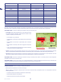
IDENTIFICATION OF MANUFACTURER AND EQUIPMENT
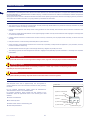
The nameplate shown here is applied directly onto the appliance. It
contains references and all the information essential for safely operating
the device.
For any technical requirements, please contact the Manufacturer’s
Technical Service Centre or an authorised dealer.
For technical assistance, please indicate the data reported on the
identification plate, the approximate hours of use and the type of fault
detected.
DATA PLATE
(A) Name of manufacturer
(B) EC conformity label
A. Name of manufacturer.
(C) Model
B. CE conformity label.
(D) Technical specifications
C. Model / serial number / manufacturing year.
(C) Serial number
D. Technical specifications.
User’s manual
2
(C) Manufacturing year
SAFETY INFORMATION
SAFETY REGULATIONS
•
During design and construction, the manufacturer carefully considered the possible hazards and personal risks that may result from
interacting with the equipment. In addition to observing the applicable laws in force, the manufacturer adopted all the “good manufacturing
practice regulations.” The purpose of this information is to inform users on the need to use extreme caution to avoid risks.
•
When using the robot for the first time, it is recommended to carefully read the whole manual and to be sure to fully understand it, especially
the safety information.
•
Lift and handle the equipment according to the information reported on the packaging, on the appliance and in the user instructions supplied
by the Manufacturer.
•
Pay attention to the symbols that appear on all the safety labels. They are coded by shape and colour for safety purposes. Keep them legible
and always follow the instructions indicated.
•
The lawn mower robot can only be used by people who know how to operate it and who have read and understood the instructions in this
manual.
•
Only use the equipment for the purposes specifically intended by the manufacturer. Improper use of the equipment may be hazardous to
personal safety and health and may lead to economic losses.
•
Before using the lawn mower robot , make sure there are no objects on the lawn (toys, tree branches, clothing items, etc.).
•
When using the robot, make sure there are no people (especially children, the elderly or disabled people) and pets in the work area so as to
prevent safety risks. To avoid this risk, it is recommended to program the robot to operate at suitable times of the day.
•
Never allow people to sit on the robot.
•
Never lift the robot to inspect the blade while it is running.
•
Do not place hands and feet under the robot when it is in operation and moving, especially near the wheel area.
•
Never remove, bypass or tamper with the safety devices installed. The failure to observe these requirements may lead to serious personal
health and safety risks.
•
Perform all maintenance activities recommended by the manufacturer. Proper maintenance will allow obtaining the best performances and
longer operating times.
•
Before maintenance or adjustments, which can also be performed by a user with minimal technical competence, disconnect the power
supply. The user must ensure that all the necessary safety conditions are in place, especially when working on the lower part of the lawn
mower robot, following the Manufacturer’s procedures and instructions.
•
Use the personal protection devices recommended by the Manufacturer, in particular, always wear protective gloves when handling the
cutting blade.
•
Before replacing the batteries, always remove the blade.
•
Make sure the air vents of the power supply unit are free and clear of residuals.
•
To avoid irreversible damage to the electric and electronic parts, do not wash the robot with water jets at a high pressure and do not immerse
it in water, partially or completely, as it is not watertight.
•
Operators who perform repairs during the working life of the robot must have the necessary technical expertise, skills and experience in this
specific field. The lack of these requirements may be hazardous to the health and safety of people.
•
Any work to be performed on the charging station must be carried out with plug of the power cord disconnected.
•
Replace any worn or deteriorated parts with original spare parts to ensure proper functioning and safety.
•
The robot cannot be used without the top cover. If the mechanical parts of the robot are damaged, replace them.
•
Any routine or extraordinary maintenance (e.g. battery replacement) must be performed by an authorised service centre.
•
The Manufacturer shall not be held liable if non-original spare parts are used.
•
Never use and recharge the robot in explosive and/or flammable environments.
3
User’s manual
EN
SAFETY DEVICES
1. Bumpers
EN
The bumper sensor is activated if the robot strikes a solid object greater than 10 cm (3.94 in.) in height, which stops the movement in that
direction and moves backwards to avoid the obstacle.
2. Inclinometer
If the robot works on a slope which is steeper than the maximum limit, or tips over, the robot will stop the cutting blade.
3. Emergency stop switch
Located on the control panel with the word STOP larger than the other commands on the keypad. Pressing this button at any time during
operation will immediately stop the movement of the lawnmower robot and the rotation of the blade will stop within 2 seconds.
4. Over-current protection
Each motor (blade and wheels) is monitored continuously during operation for any situation that may cause them to overheat. If this occurs
in the wheel motor, the robot will attempt to move in the opposite direction. If the over-current persists, the robot will stop and signal an error.
If the cutting blade motor overheats, there are two intervention ranges. If the parameters fall within the first range, the robot will perform the
manoeuvres to unblock the cutting blade. If the over-current is below the protection range, the robot will stop and signal a motor error.
5. No sensor signal
If there is no signal on the perimeter cable, the robot will automatically stop.
6. Lifting sensor
If the robot is lifted from the ground by the central handle, the cutting blade will stop rotating.
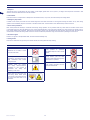
SAFETY SIGNALS
This
product
is
password
protected. Keep the code in a safe
place.
Attention! Do not clean or wash
the robot with water.
Carefully
read
the
user
instructions and ensure that you
fully understand them before
using the robot.
Keep children, pets and other
people a safe distance away when
the robot is in operation.
Carefully follow the warning
and safety recommendations
contained in this manual to
guarantee
the
safety
and
efficiency of the robot.
This product complies with the
current CE directives.
Keep hands and feet away from
the cutting blade. Never place
your hands or feet under the body
or close to the robot when it is in
operation.
User’s manual
4
TECHNICAL INFORMATION
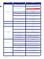
TECHNICAL SPECIFICATIONS
EN
Model
Description
075BA0
075DE0
075EV0
075EV1
075EL0
400 ( 4304 )
600 ( 6460 )
1200
( 12912 )
1600
( 17216 )
2200
( 23672 )
Maximum recommended surface that can be mowed
Robot
m2 (sq ' )
Features
Dimensions (W x H x D)
Robot weight (incl. battery)
mm (“)
kg
Cutting height (Min-Max)
mm (“)
Diameter of blade with 4 cutting edges
mm (“)
Electric motors
Cutting blade speed
Ground speed
575x282x438 ( 22,64 x 11,10 x 17,25 " )
11
220 ( 8,66 " )
240 ( 9,45 " )
%
Ambient operating temperature
Max°
240 ( 9,45 " )
290 ( 11,42 " )
cc. (25.2 V)
without
brushes
cc. (25.2 V) with brushes
RPM
Maximum recommended slope
11,6
20-65 ( 0,79-2,56 ")
V
Metres / Minute
11,3
3600 Cutting
3300 Maintenance
20 (65.6 ')
30 (98.43 ')
45%. Allowable, based on the lawn conditions and accessories installed.
35%. Maximum. In conditions of a trimmed lawn.
20%. In proximity of the outside edge or perimeter wire.
ROBOT -10°(14 F.) (Min) +50° (122 F.) (Max)
BATTERY CHARGER -10°(14 F.) (Min) +40° (104 F.) (Max)
Measured noise level
dB(A)
72 (Max) − 65 (lawn maintenance)
Water protection class
IP
IP21
Electrical features
Meanwell apparatus certificate No. E307078 –
Class 2 (Vin 90 – 264 Vac)
AC current (typ.) 1.2A/115Vac 0.7A/230Vac Input Frequency range 47 - 63Hz
Power supply unit (for lithium battery)
Class 1 (Vin 90-295 Vac
47/63Hz) AC Current (typ.) 2
A/115 Vac 1 A/230 Vac
Type of accumulator and charging batteries
Rechargeable Lithium-Ion Battery
V-A
25.2V – 1x2.3Ah
25.2V –
2x2.3Ah
25.2V – 6.9Ah
Battery charger
V-A
29.3 Vcc - 2,3 Ah
29.3 Vcc - 2,3
Ah
29.3 Vcc - 5.0 Ah
1:15 - Automatic
2:00 Automatic
3:00 - Automatic
0:40
1:30
Average recharging time and method
Average operating time (*)
Hours
2:30
3:00
Blade safety stop
Rollover sensor
standard
Handle sensor
standard
Emergency button
standard
Equipment and accessories
Perimeter wire
m(')
Maximum
length
of
perimeter
wire
(approximate, calculated based on a regular
perimeter)
m(')
100 ( 328 ' )
400 (1312 ')
5
150 ( 491 ' )
600 (1968 ' )
User’s manual
Fastening pegs
No.
Areas managed, including the primary one
EN
100
2
200
3
4
TX-S1 perimeter signal (patented)
standard
Rain sensor
standard
Blade modulation and intelligent spiral
standard
Mowed lawn sensor – Self-programming
(patented)
not available
Acoustic alarm
Optional
standard
External box for holding the battery charger
Power supply safety box
Optional
(*) Depending on the condition of the grass and lawn surface
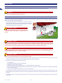
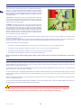
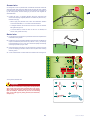
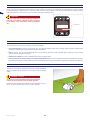
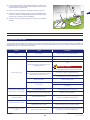
GENERAL DESCRIPTION OF THE APPLIANCE
The appliance is a robot designed and built to automatically trim grass
in gardens and house lawns at any time of the day or night. It is small,
compact, silent and easy to transport.
Depending on the characteristics of the surface to be trimmed, the robot
can be programmed to work on more than one area: a primary area and
secondary areas (according to the specifications of the various models).
During operation, the robot trims the area marked off by the perimeter wire.
When the robot detects the perimeter wire or encounters an obstacle, it
changes direction in a random manner and starts mowing again in a new
direction.
According to its operating principle random, the robot automatically trims
the entire delimited area of the lawn (see figure).
The robot is able to recognise the presence of higher and/or thicker grass
in an area of the garden and to automatically activate, if considered
necessary, the spiral movement for a perfect finish. The spiral movement
can also be activated by pressing ENTER/MENU while the robot is mowing.
The lawn surface that the robot is able to trim depends on a series of
factors, such as:
•
model of the robot and type of batteries installed
•
characteristics of the area (irregular perimeters, uneven surfaces,
divided areas, etc.)
•
characteristics of the lawn (type and height of the grass, moisture, etc.)
•
conditions of the blade (level of sharpness, without residuals and
deposits, etc.)
User’s manual
6
RANDOM OPERATION
standard
MAIN PARTS
1. Robot.
2. Keyboard commands: for setting and displaying the operating modes of the robot.
EN
3. Rain sensor: detects rain and commands the robot to return to the charging station.
4. Battery: supplies power to the motors of the blade and drives the wheels. The robot is supplied with one or more lithium batteries located
under the models already assembled in some models.
5. Handle: for lifting and carrying the robot.
6. Cutting blade : cuts the grass already assembled in some models.
7. Perimeter wire coil: cable with special insulation and special features for carrying the signal needed to operate the robot.
8. Pegs : for securing the perimeter wire and the charging station.
9. Power cord for the power supply unit.
10. Power Supply unit : supplies power in low voltage to the batteries.
11. Charging station: for recharging or keeping the robot charged.
12. Transmitter: transmits the signal to the perimeter wire.
13. User manual.
14. Key for adjusting the cutting height.
2
3
7
10
8
1
4
14
5
13
6
11
9
12
7
User’s manual
INSTALLATION
PACKING AND UNPACKING
EN
The equipment is delivered suitably packaged. When unpacking, carefully remove and check the integrity of the parts.
Important
•
Keep the packaging materials for future use.
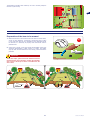
PLANNING OF SYSTEM INSTALLATION
The robot is not difficult to install, but requires some preliminary planning in order to find the best area for installing the charging station, power
supply unit and for laying out the perimeter wire.
•
The charging station must be positioned on the edge of the lawn,
preferably in the largest area from which other areas of the lawn are
easily accessible. The area where the charging station is installed is
hereinafter referred to as the “Primary Area.”
Power supply unit
Warning – Caution
transmitter
Position the power supply unit in an area that cannot be
reached by children. For example, at a height above 160
cm (63 ").
Min. height. 160 cm
/ 63 "
perimeter wire
charging station
Warning – Caution
When connecting the electricity, it is necessary that a power outlet is positioned near the installation area. Make sure the
connection to the mains power complies with the applicable laws. To operate in complete safety, make sure the electrical
system, which is connected to the power supply unit, is equipped with a well-functioning earthing system.
Important
It is advisable to install the unit in a cabinet for electric components (for outdoor or indoor use), equipped with a key lock,
and well-ventilated to maintain a correct air circulation.
Warning – Caution
Make sure only authorised people have access to the power supply.
•
The robot must be able to easily find the charging station at the end of the work cycle, which will also be the starting point for a new work
cycle and for reaching any other work areas, hereinafter referred to as “Secondary Areas.”.
•
Position the charging station according to these rules:
-
On level ground.
On compact and stable ground with good drainage.
Preferably in the area of the longer lawn.
In case of sprinklers, make sure the water jets are not directed inside the charging station.
Make sure the entrance of the charging station is positioned as shown in the figure, so that the robot can enter it by following the perimeter
wire in a clockwise direction.
There must be a straight area of 400 cm (157.48 ") in front of the base.
•
The charging station must be well fastened to the ground. To prevent a small step from forming at the front of the base, position a small
piece of fake grass at its entrance to stop this from occurring. Alternatively, remove part of the grassy surface and install the base flush with
the grass.
•
The charging station is connected to the power supply unit via a cord that must move away from the charging station on the outside of the
cutting area.
User’s manual
8
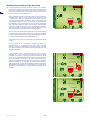
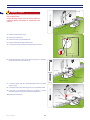
•
•
Position the power supply unit according to these rules:
OK
OK
If positioned outdoors, the robot must not be exposed to direct
sunlight and water. Therefore, it must be protected inside a
ventilated box. Do not position in direct contact with the soil or
humid environments.
NO
NO
-
Position it on the outside of the lawn and not inside.
NO
NO
-
Stretch out the excess cord going from the charging station to the
power supply unit. Do not shorten or lengthen the cord.
-
In a well-ventilated area protected against atmospheric agents and
direct sunlight.
-
Preferably inside your home, a garage or shed.
-
The incoming section of the wire must be straight and aligned
perpendicularly to the charging station by at least 200 cm (78.74 in.)
and the outgoing section must move away from the charging station as
shown in the figure; this allows the correct re-entry of the robot.
power supply unit
charging station
min height 160 cm
/ 63 "
perimeter wire
min. distance
200 cm
/ 78,74 "
transmitter
If the robot is installed near an area which has another robot (from the
same or another manufacturer), then the transmitter and receiver of the
robot must be modified during installation so that the frequencies of the two
robots do not interfere with other.
SETTING UP OF THE PERIMETER WIRE
Before installing the perimeter wire, it is necessary to check the entire
surface of the lawn. Make any necessary adjustments to the grassy
surface during the laying of the perimeter wire in order to allow the robot
to function correctly.
track for laying the perimeter wire
1. Evaluate the best method for returning to the charging station according
to the instructions described in the chapter “RE-ENTRY METHOD TO
THE CHARGING STATION”.
24 v
2. Evaluate whether a special installation of the perimeter wire is
necessary according to the instructions described in the chapter
“SET-UP OF THE ROBOT’S QUICK RE-ENTRY TO THE CHARGING
STATION”.
3. Preparation and defining of the work areas.
4. Installation of the perimeter wire.
5. Installation of the charging station and power supply unit. When laying
the perimeter wire, respect the installation direction (clockwise) and
the rotation direction around the flowerbeds (counter-clockwise), As
shown in the figure.
9
User’s manual
EN
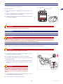
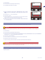
RE-ENTRY METHOD TO THE CHARGING STATION
EN
The robot can return to the charging station in two different ways based on
what is set in the user menu under the field “Settings – Re-entry to Base.”
Use the “On the Wire” method only when there are numerous obstacles
inside the garden and near the perimeter wire (within 2 meters). In all other
cases it is better to use the “V-METER” method for the quickest re-entry to
the charging station.
“Follow wire”. This method of re-entry to the charging station commands
the robot to follow the perimeter wire, positioning its wheels on either side
of the wire. If this method is activated, there is no need to prepare the
“Recall on Wire” as described below.
5 cm.
“V-METER”. By setting this method of re-entry to the charging station, the
robot runs along the perimeter wire at an indicative distance ranging from
a few centimetres to one meter (3.2 '), touching it every now and again in
the curved sections until it recognises the “Recall on the Wire” necessary
to properly steer the robot to the charging station or to guide it along narrow
sections. Once the “Recall On the Wire” has been recognised, the robot
will follow the perimeter wire, positioning its wheels on either side of the
wire for a distance of around 10 meters. (33 ').
2 mt.
4-10 mt.
2 mt.
step
lower 2 mt.
4-10 mt.
The “Recall on the wire” not only indicates to the robot that it is near the charging station, but also of a narrow passage or of an arrow for quick
re-entry to the charging station.
As soon as a “Recall” is recognised, the robot will follow the perimeter wire at low speed, and with more precision for around 10 meters (33 '). It
will then return to the “V-Meter” re-entry mode if it does not encounter the charging station or the arrow for quick re-entry.
Follow these instructions to install the “Recall.”
•
The “Recall” is a piece of wire that extends for around 2 m (6.6 ') with a distance of 5 cm (1.96 ") between each wire.
•
The “Recall” must be positioned at a distance of 4 and 10 m. (13.2 - 33 ') in front of the charging the station.
•
The “Recall” must be positioned at a distance of 2 m. (6.6 ') in front of any narrow passages.
•
The “Recall” must be positioned in the section in front of the “Quick Re-entry.”
NB: If the robot does not find the charging station within a certain amount of time, it will follow the perimeter wire in “Follow wire”
mode.
SETUP OF THE ROBOT’S QUICK RE-ENTRY TO THE CHARGING STATION
Quick re-entry requires a special installation of the perimeter wire that allows the robot to reduce the re-entry path to the charging station. This
special installation of the perimeter wire should only be used for gardens where quick re-entry significantly reduces the path and where the
perimeter length is greater than 200 meters.
To setup the quick re-entry, position the perimeter wire on the ground so that it forms a triangle with one side of 50 cm (19.7 ") and the other two
sides of 40 cm (15.75 ") each, as shown in the figure.
As the robot heads back to the charging station with the two wheels on either side of the wire, it intercepts this triangle and stops moving. It
then turns approximately 90° towards the inside of the garden and starts moving in the new direction until running into the perimeter wire on the
opposite side.
Arrange the wire for quick re-entry in a point where there is at least 200 cm (78.74 ") of straight wire in front of the station, and at least 150 cm
(59.05 ") of straight wire behind it.
Do not set up the wire along the straight section immediately in front of the charging station or near any obstacles. Make sure there are no
obstacles along the re-entry path that may obstruct the quick re-entry.
Important
An incorrect setup of the robot’s quick re-entry may prevent the robot from returning to the charging station quickly. When
the robot travels along the perimeter to reach a secondary area, it may not detect the quick re-entry setup.
User’s manual
10
The illustration provides some useful tips on how to correctly setup the
robot for a quick re-entry.
EN
50
40
4-10 mt.
40
min. 150 cm.
(59,05 ")
5 cm.
2 mt.
4-10 mt.
2 mt.
step
lower 2 mt.
4-10 mt.
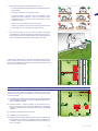
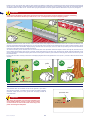
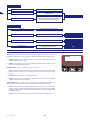
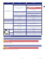
PREPARATION AND MARKING THE BOUNDARIES OF THE WORK AREAS
Preparation of the lawn to be mowed
1. Make sure the lawn to be mowed is even and does not contain holes,
NO
stones or other obstacles. If necessary, prepare the lawn by filling
in any holes and removing any obstacles. If some obstacles cannot
be removed, it is necessary to properly mark these areas with the
perimeter wire.
2. Check that no areas of the lawn exceed the allowable slopes (see
“Technical Specifications”). When working on slopes, the wheels
may slip when the robot detects the wire, causing it to fall outside the
perimeter.
Important
Areas with slopes greater than those allowed cannot be
mowed with the robot. Therefore, position the perimeter
wire in front of the slope so that it is excluded from the
area to mow.
0-20%
21-35%
OK
0-20%
OK
21-35%
NO
OK
OK
perimeter wire
perimeter wire
35 %
100 cm (39,3 ")
NO
35 cm
(13,78 ")
35 cm
(13,78 ")
0-35%
11
0-20%
User’s manual
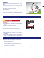
Marking the boundary of the work area
3. Check the entire lawn surface and assess whether it is necessary
EN
to divide it into separate work areas as per the rules described here
below. Before installing the perimeter wire, check the entire path to
make this procedure easier. The illustration shows a lawn with the
track for installation of the perimeter wire.
During installation, identify any secondary areas and closed areas. A
secondary area is part of a lawn connected to the primary lawn with
a passage that is difficult to reach by the robot's normal movement.
The area must be reachable without any rises or drops greater than
those allowed. Whether a zone is to be defined a “secondary area”
also depends on the size of the primary area. The larger the primary
area, the harder it will be to reach narrow passages. More gener